Discrete Phase Model (DPM): Droplet & Multi-component Evaporation
Introduction
This section will investigate the evaporation process modeling in Ansys Fluent software. Two main methods will be discussed separately. Droplet evaporation & Multi-component evaporation.
-
Droplet Evaporation
The evaporation process should be studied from two different aspects; Heat transfer and mass transfer. Wherever there is a temperature gradient between droplet and ambient, heat transfers from the higher temperature to below. Therefore, as the droplets inject into the hot domain, the heat transfer begins, and the droplet’s temperature increases until it reaches vaporization temperature. Note that the saturation vapor pressure at the droplet’s surface rises due to higher temperatures. The concentration gradient of evaporative species between the droplet’s surface and its environment controls mass transfer. Check figure 1. In addition, UDF is required for Ansys Fluent to simulate condensation.
Figure1
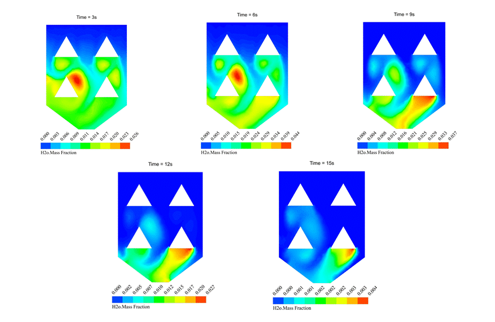
As the H2O mass fraction contour one shows, evaporation happens after the injection of wet rice particles into the hot ambient of the rice drying device. The simulation is done using evaporating droplets, which has been discussed earlier. For more details, check the link.
Contour 1
Particle Heat & Mass Transfer Laws
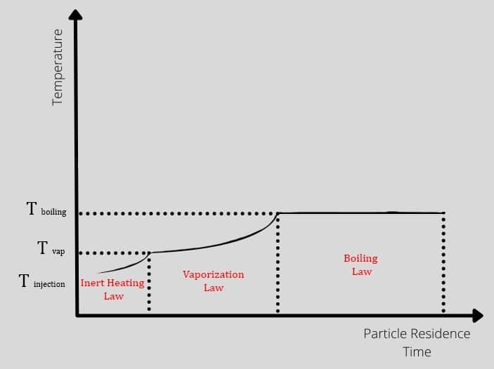
The droplet could experience three different periods after injection, and each period has its laws and equations from the heat transfer aspect. The particles enter the hot domain with injection temperature, increasing to vaporization temperature over time. So in this zone, Tp<Tvap also is known as inert heating zone. After that, the process continues in the vaporization zone until the temperature gets to boiling point. In other words, the vaporization occurs where Tvap<Tp<Tbp. Check out figure 2.
Figure2
Theoretically, heat is transferred between the droplet and its environment through convection and radiation mechanism (Figure 3). The first law of thermodynamics states that a system’s total energy and surroundings are conserved. Note that the droplet is assumed to be spherical, and Nusselt number is defined as:
h: heat transfer coefficient, dP: particle diameter, : thermal conductivity coefficient of the environment, Re: Reynolds number, Pr: Prandtl number.
Figure3
To obtain the governing equations, remind that there is no evaporation and mass transfer in the inert heating zone (Tp<Tvap), So, According to the first law of thermodynamics:
As the droplet’s temperature enters the vaporization zone(Tvap<Tp<Tbp), evaporation is being taken place, so another term is added to the previous equation:
Moreover, From the mass transfer aspect, the driven force for mass transfer is the difference of the vapor concentration at the droplet surface and its environment, shown in figure 1. Vapor concentration is equal to its value at the saturated condition at the droplet surface, defined as:

Figure4
Fundamentally, during law 2, the vaporization rate is defined by gradient diffusion that relates flux of vapor part of the droplet to the gas phase of ambient. As mentioned before, the driven force is the difference between the vapor concentration of the droplet’s surface and its environment:
: Molar flux of vapor(kg mol/m2-s),
: Mass transfer coefficient(m/s), :
vapor concentration at the droplet surface (kgmol/m), :
vapor concentration in the bulk gas (kgmol/m^3), R: Universe constant gas, :
Local bulk temperature in the gas,
: Particle surface temperature,
: Saturation vapor pressure,
: Local bulk mole fraction of species i.
Eventually, the mass transfer coefficient is calculated from the Sherwood number correlation:
: diffusion coefficient of vapor in the bulk (
),
: Schmitt number

Note that saturation vapor pressure() and diffusion coefficient of vapor in bulk(
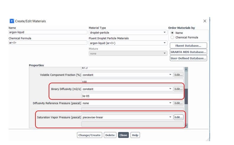
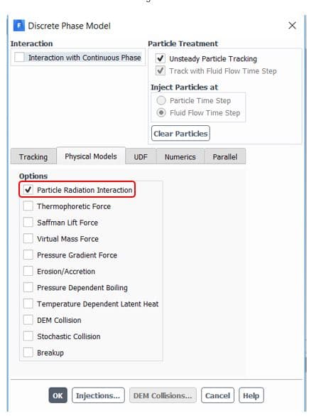
) should be defined manually in the software from the Materials section(figure 5). Also, to consider radiation terms in calculations, you need to determine the P1 or discrete ordinates (DO) radiation model from Models => Radiation and then active Particle Radiation Interaction from discrete phase window (figure 6).
Figure5
Figure6
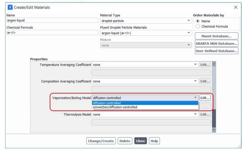
By default, Ansys Fluent uses the diffusion-controlled model for the vaporization/boiling model. We don’t get into more details in this article, but it would be better to use a convection/diffusion-controlled model when high evaporation rates. For slowly evaporating droplets, both models are expected to give similar results. It is available in the materials tab, as shown in figure 7.
Figure7
When the droplet’s temperature reaches boiling point , the droplet remains at a fixed temperature (
), and the third law is applied to predict the convective boiling of a discrete phase droplet. Note that the model requires
and without considering radiation terms, the governing equation is defined as:
: heat capacity of gas(J/kg-K),
: droplet density(kg/m^3),
: thermal conductivity of the gas (W/m-K)
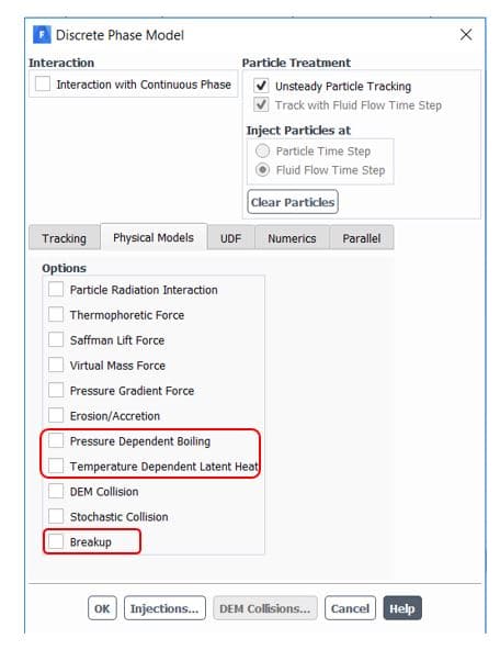
Furthermore, Ansys fluent provides sub-models for better accuracy in the DPM panel(figure 8). The temperature dependent latent heat model automatically applies by enabling pressure dependent boiling. It requires appropriate droplet saturation vapor pressure definition to completely cover pressure/temperature range and efficient switching between laws 2 and 3. Another provided option is the breakup of droplets that collect newly generated child droplets and track them simultaneously. As a result, higher accuracy and faster convergence are attained.
Figure8
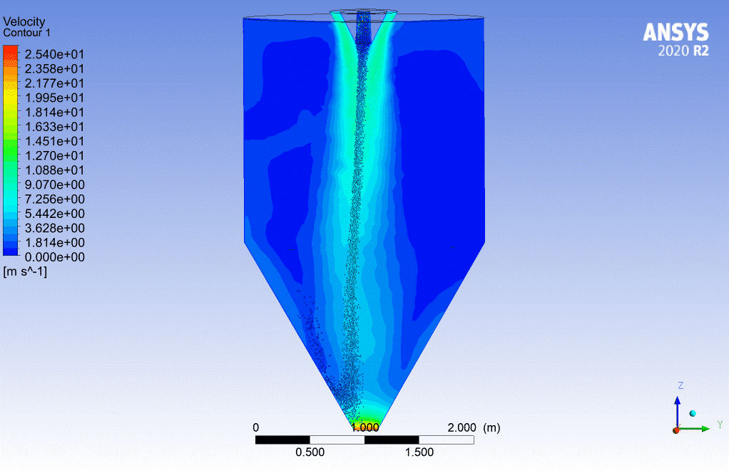
You can use widely the evaporating droplets in many simulations directly or indirectly related to the evaporation process. For instance, the spraying simulation in a chamber may not seem to be related to evaporating droplets directly. Still, the injected particles could evaporate during the simulation, so it must be considered. For more information, visit the link below, contour 2.
Contour2.Spray Drying Chamber
-
Multi-component Evaporation
Compared to the droplet evaporation model, the multi-component evaporation model is more comprehensive and closer to the actual liquid evaporation because real liquid consists of multiple species, each with its specific properties. Naturally, the light components vaporize first and leave the heavier components, which take longer to vaporize. By employing a multi-component model in Ansys Fluent software, we can define several species and their components. Still, it also requires accurate input parameters, including partial pressure, mass fraction of each component, etc.
Evaporation rate of multi-component liquid
As mentioned in evaporating droplet’s blog, the driven force of vapor flux is the difference between the vapor concentration of the droplet’s surface and its environment. In a multi-component model, the parameters should be defined for each species:
: Molar flux of vapor(kg mol/m2-s),
: Mass transfer coefficient(m/s), :
vapor concentration at the droplet surface (kgmol/m),
: vapor concentration in the bulk gas (kgmol/m^3), R: Universe constant gas,
: Particle surface temperature,
: the partial pressure of species
Theoretically, the partial pressure of species is calculated from the equation:
: Fugacity coefficient of species I,
: Equilibrium mole fraction of species i in gas phase,
: Activity coefficient of species I,
: Equilibrium mole fraction of species i in liquid condensed phase,
: Fagucity coefficient of pure species i at saturated pressure, :
Saturated pressure of species i,
: Molar volume fraction of the liquid
In Ansys Fluent software, the above equation simplifies by considering the gas to be ideal. It is known as Reuolt’s law, So the vapor-liquid equilibrium expression is:
Setting up multi-component Evaporation model
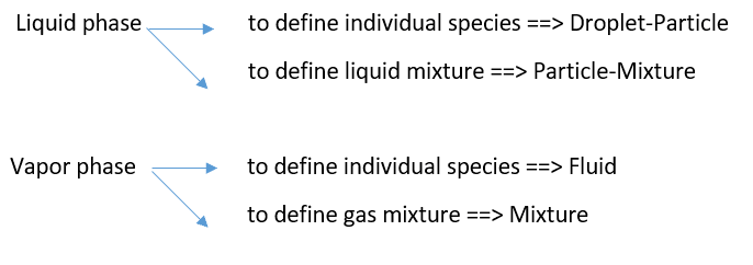
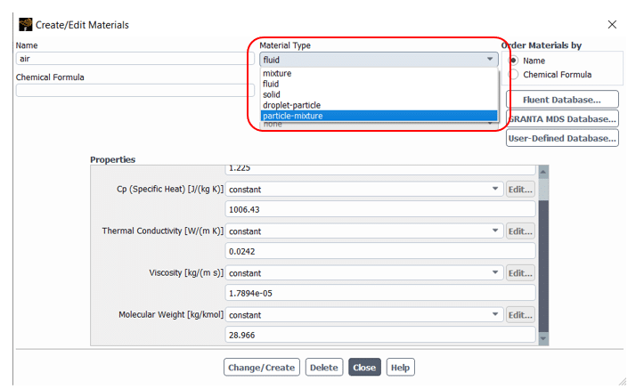
Before getting to the injection part, we need to define both liquid and vapor phase species in the Materials tap shown in figure 9. To do that, follow the steps:
Figure 9
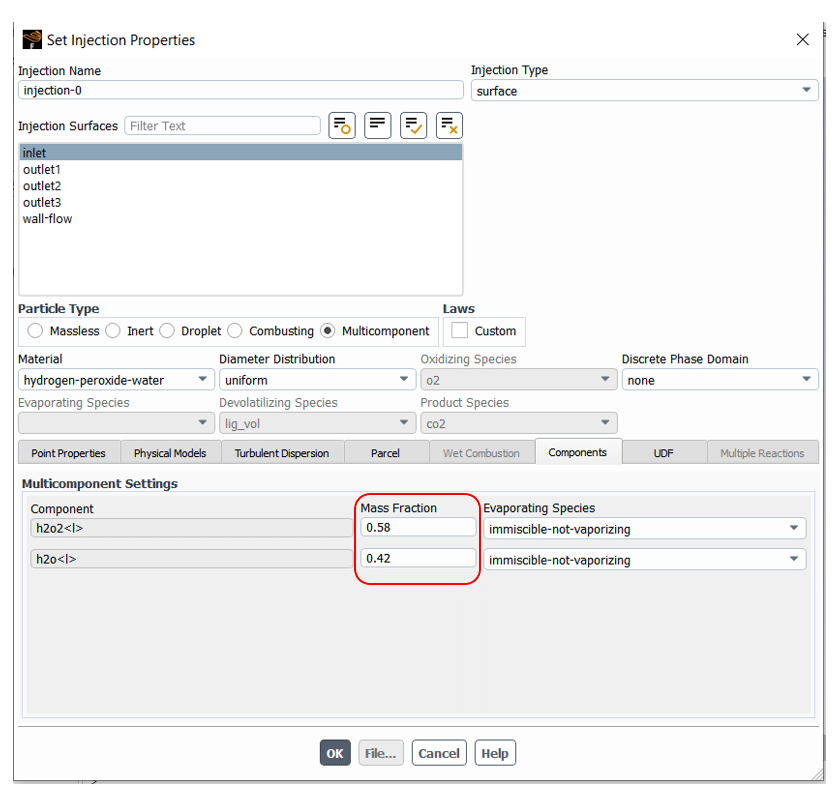
After that, the multi-components settings are accessible in the Injection section. As shown in figure 10, the mass fraction of components can be set in Multi-component Setting located in the Components tab.
Figure 10








Comments (0)