
DPM Atomizer Models (Part I): Plain-Orifice & Pressure Swirl Atomizer Models
Introduction
In this article, different types of atomizers are introduced. Also, Plain-Orifice and Pressure Swirl atomizer models are discussed.
Type of Atomizers
ANSYS FLUENT offers sophisticated injection types for sprays that describe breakup phenomena. For most injections, you must provide the particles’ initial diameter, position, and velocity. However, sprays’ models for predicting droplet size and velocity distribution are used. The droplets must be randomly distributed spatially with a dispersion angle and time for an accurate Atomizer simulation. For Non-atomizer injection, all droplets are injected along a fixed path at the beginning of the time step. Atomizer models use randomly selected tracks and zigzags (Staggering) to achieve a random distribution.
1. Pressure atomizers
We use this method when a liquid is discharged through a small hole under high pressure:
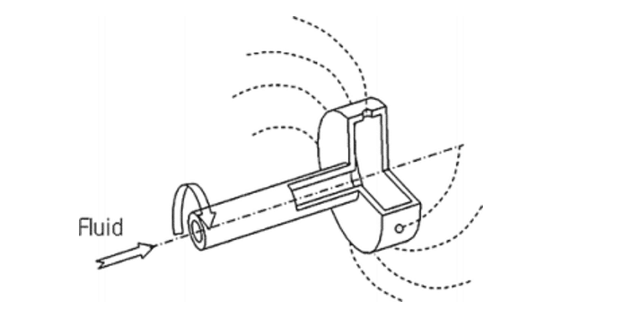
2. Rotary atomizers
It consists mainly of a high-speed rotating disk with a device for inserting liquid in the center.
3. Air-assist/Air-blast atomizers
The air blast atomizer injector model exposes a liquid stream to a high-velocity gas stream. This model is taken from the Pressure swirl atomizer model. One of the most important differences between the two models is that the thickness of the liquid sheet enters directly into the air blast atomizer model. This input is required due to the variety of sheet forming mechanisms used in Air-assist / Air-blast atomizers. On the other hand, you can specify the maximum relative velocity between the air and the liquid sheet. Although this value can be calculated, setting a specific value frees you from the need to resolve the flow inside the atomizer accurately. This feature is suitable for simulating the computational ranges of places where the atomizer dimensions are very small compared to the whole computational domain.
DPM Atomizer Models
- Plain Orifice Atomizer
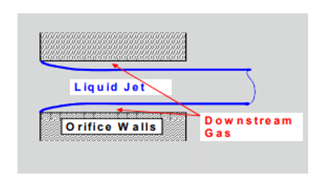
The plain orifice is the most common type of atomizer. In the simple Atomizer at ANSYS FLUENT, the liquid accelerates through a nozzle, forms a liquid jet, and then decomposes to form droplets.
DPM Spray Regimes
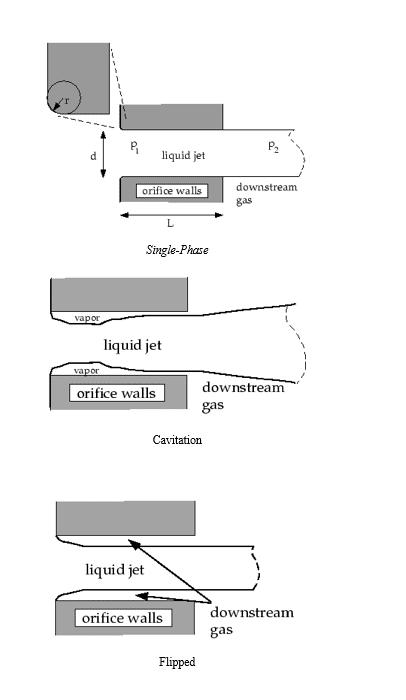
This seemingly simple process is complicated. Simple craters may operate in three regimes:
The transition between regimes is sudden and produces different sprays. The internal velocity at the orifice outlet determines the initial droplets’ size and dispersion angle. A plain-Orifice Atomizer is a plate with a round hole; most diesel injectors are of this type.
The simple aperture model in ANSYS FLUENT must accurately predict spray properties and identify the correct internal nozzle flow status because the nozzle position has an extraordinary effect on the external spray. Unfortunately, there is no fixed theory for determining the status of the nozzle. We can drive experimental models from experimental data. ANSYS FLUENT uses several dimensionless parameters to determine the internal flow regime for the simple aperture atomizer model. These parameters and the decision process are summarized below.
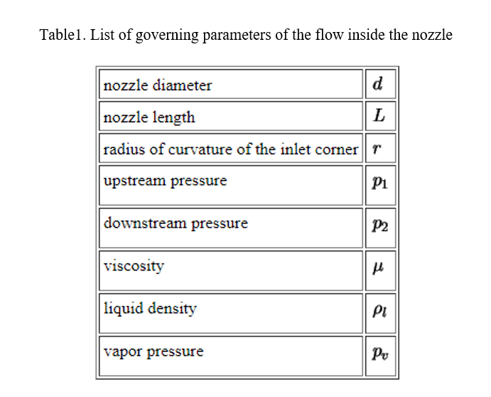
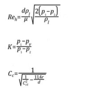
Table 1 provides a list of parameters needed to determine and control the flow inside the nozzle. These parameters may be combined to form dimensionless characteristic lengths such as r / d and L / d and dimensionless groups such as the hydraulic head Reynolds number (Reh) and the cavitation parameters (K).
The fluid flow often compresses in the nozzle, as seen in Figures. Nurick found it helpful to use the coefficient of contraction (Cc) to show a reduction in the cross-section of a liquid jet. We can define the compression coefficient as the area of the shrinking fluid flow over the entire cross-section of the nozzle. ANSYS FLUENT uses the Nurick fit for the coefficient of contraction.
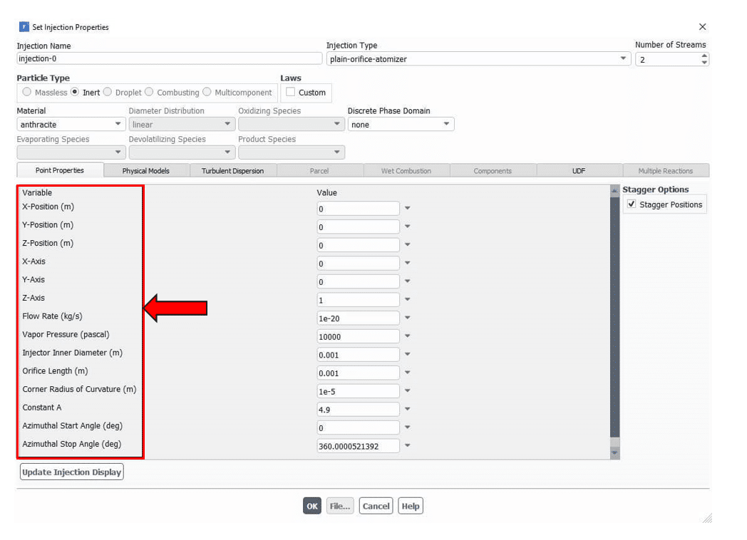
Inputs related to the Plain-Orifice Atomizer model
- Atomizer location
- Axis (3D)
- Mass flow rate
- Start and stop times
- Injection pressure
- Orifice diameter (d)
- Orifice length (L)
- Inlet corner radius of curvature (r)
- Spray angle Constant A (typically, 4-6)
- Azimuthal start and stop angles (3D)
- Pressure Swirl Atomizer
Another practical type of atomizer is the Pressure Swirl Atomizer, one of the most important injectors for spraying liquids, especially in propulsion systems. This atomizer is also known in the gas turbine as the Simplex Atomizer. This atomizer accelerates the liquid into the central rotation chamber through nozzles known as rotary inputs. The rotating fluid presses against the walls of the rotating chamber, creating a hollow air core. It then emerges from the hole as an unstable thin sheet that breaks down into droplets. With direct spark injection, a pressure swirl atomizer is widely used in gas turbines, oil furnaces, and car engines.
The interaction between air and liquid sheet is still not very clear. Aerodynamic instability is thought to cause liquid sheet break up. The mathematical analysis assumes that Kelvin-Helmholtz waves grow on the liquid sheet and gradually break into liquid filaments. The fibers are then broken into droplets due to varicose instability. After the droplets’ emergence, the spray process’s evolution is observed concerning drag, collision, coalescence, and secondary breakup.
The pressure-swirl atomizer model used in Fluent software is also known as the Linearized Instability Sheet Atomization (LISA) model developed by Schmidt et al. Lisa’s model is divided into the following two steps:
- Film formation
- Sheet breakup and pulverization
Both parts are described in detail below.
Film formation in a pressure-swirl atomizer
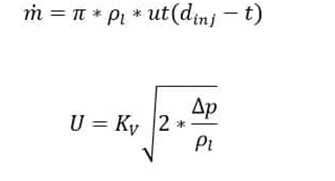
The radial motion of the fluid inside the injector produces an air core in the center surrounded by a liquid film. The thickness of the liquid film at the injector output, “t”, is a function of the flow rate (Equation 1). The accuracy of calculating the axial component of velocity, “u”, depends on knowing the details inside the injector. Therefore it is challenging to determine it from the general specifications of the injector. Han et al. approximation has been used. It is assumed that the total flow velocity depends on the injector pressure.
injector outer diameter
Effective mass flow rate:
u: Axial component of speed at injector output
Kv: Velocity coefficient
Lefebvre emphasizes that K_V is a function of injector design and working pressure. If the rotating ports are considered nozzles and assume that most of the pressure drop occurs in these ports, K_V will be the same as the discharge coefficient (Cd). For single-phase nozzles with sharp inlet corners and an L / d (length to diameter) of 4, a Cd value of 0.78 or less is considered. If the nozzle is cavitating, the Cd may drop to 0.61. Therefore, a value of 0.78 can be regarded as the upper experimental range for K_V. It is estimated that the effects of other momentum reduce the K_V value by 10% to 0.7.
Kv physical ranges require less than an energy conservation unit but are large enough to provide a sufficient mass flow. To ensure that the air-core size is not negative, the following expression is used for Kv:
Assuming Δp is known, Equation 2 can be used to find U, and given the relation u = UCosθ, where it is assumed that the value of θ, the half-angle of the spray, is known, the equation of the constraint Kv is obtained.
Inputs for Pressure Swirl Atomizer Model DPM Spray
- Atomizer location
- Axis (3D)
- Mass flow rate
- Start and stop times
- Inner diameter
- Spray half-angle
- Upstream pressure
- Sheet constant
- Ligament constant
- Azimuthal start and stop angles (3D)
DPM Spray Pressure Swirl Atomizer
Another essential type of atomizer is the Pressure Swirl Atomizer, one of the most important injectors for spraying liquids, especially in propulsion systems. This atomizer is also known in the gas turbine as the Simplex Atomizer. This atomizer accelerates the liquid into the central rotation chamber through nozzles known as rotary inputs. The rotating fluid presses against the walls of the rotating chamber, creating a hollow air core. It then emerges from the hole as a thin sheet that is unstable and breaks down into droplets. Pressure swirl atomizer is widely used to combustion liquid fuel in gas turbines, oil furnaces, and car engines with direct spark injection.
The interaction between air and liquid sheet is still not very clear. Aerodynamic instability is thought to cause liquid sheet break up. The mathematical analysis assumes that Kelvin-Helmholtz waves grow on the liquid sheet and gradually break it into liquid filaments. The fibers are then assumed to break into droplets due to varicose instability. After the droplets’ emergence, the spray process’s evolution is observed concerning drag, collision, coalescence, and secondary break up.
The pressure-swirl atomizer model used in Fluent software is also known as the Linearized Instability Sheet Atomization (LISA) model developed by Schmidt et al. Lisa’s model is divided into the following two steps:
- Film formation
- Sheet break up and pulverization
Both parts are described in detail below.
Film formation in a pressure-swirl atomizer
The radial motion of the fluid inside the injector produces an air core in the center that is surrounded by a liquid film. The thickness of the liquid film at the injector output, “t”, is a function of the flow rate (Equation 1). The accuracy of calculating the axial component of velocity, “u”, depends on knowing the details inside the injector. Therefore it is challenging to determine it from the general specifications of the injector. To solve this problem in software such as Fluent, Han et al. Approximation has been used. So (Equation 2), it is assumed that the total flow velocity depends on the injector pressure.
injector outer diameter
Effective mass flow rate:
u: Axial component of speed at injector output
Kv: Velocity coefficient
Lefebvre emphasizes that K_V is a function of injector design and working pressure. If the rotating ports are considered nozzles and assume that most of the pressure drop occurs in these ports, K_V will be the same as the discharge coefficient (Cd). For single-phase nozzles with sharp inlet corners and an L / d (length to diameter) of 4, a Cd value of 0.78 or less is considered. If the nozzle is cavitating, the Cd may drop to 0.61. Therefore, a value of 0.78 can be regarded as the upper experimental range for K_V. It is estimated that the effects of other momentum reduce the K_V value by 10% to 0.7.
Kv physical ranges require less than an energy conservation unit but are large enough to provide a sufficient mass flow. To ensure that the air-core size is not negative, the following expression is used for Kv:
Assuming Δp is known, Equation 2 can be used to find U, and given the relation u = UCosθ, where it is assumed that the value of θ, the half-angle of the spray, is known, the equation of the constraint Kv is obtained.
Inputs for Pressure Swirl Atomizer Model DPM Spray
- Atomizer location
- Axis (3D)
- Mass flow rate
- Start and stop times
- Inner diameter
- Spray half-angle
- Upstream pressure
- Sheet constant
- Ligament constant
- Azimuthal start and stop angles (3D)
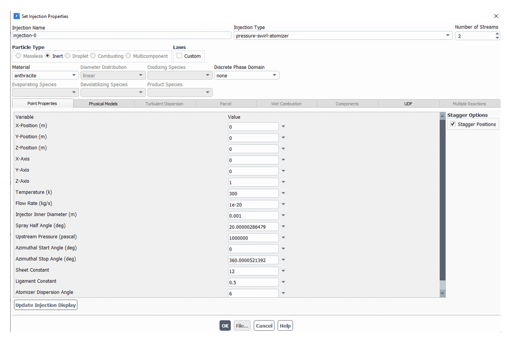
In Fluent software, each of these inputs is as follows:
Air-Blast/Air-Assisted Atomizer Model DPM Spray
The Fluent Air-Blast / Air-Assisted Atomizer model is a derivative of the Pressure Swirl Atomizer model. An additional air stream is often directed through the atomizer to accelerate the decomposition of liquid sheets. The liquid is converted to a sheet by a nozzle, and then air is directed to the sheet to increase atomization. This technique is called air-assisted atomization or blast atomization, depending on the amount of air and its velocity. Adding outside airflow to the side of the screen produces smaller droplets than without air.
Although the exact mechanism of this enhanced performance is not fully understood, it is thought that contributing air may accelerate sheet instability. Air may also help disperse the droplets and prevent them from colliding. Air-assisted atomization is used in many similar applications of the Pressure Swirl Atomizer.
As mentioned earlier, the Fluent Air-Blast / Air-Assisted Atomizer is a derivative of the Pressure Swirl Atomizer model. One of the most important differences between the two models is that the thickness of the liquid sheet enters directly into the air blast atomizer model. This input is necessary due to the variety of sheet forming mechanisms used in air blasting atomizers. Therefore, the air blast atomizer model does not use any of the appropriate equations to model the sheet formation used in the rotational compression atomizer model.
Another critical difference is that in the air explosion atomizer model, it is assumed that the breaking of the liquid sheet always occurs due to short waves. This assumption is also since the thickness of the sheet is higher in air explosion atomizers. As a result, the diameter of the ligaments is a linear function of the wavelength of the fastest wave generated on the liquid sheet and is calculated using the following equation:
Other inputs for this model are the same as the rotational pressure model, among which we can mention the flow rate and flow velocity, which we can see in the following figure of these inputs:
In the air blast model, the atomizer angle is the initial path of the liquid film when leaving the orifice. As you can see, the default value of this angle is 6 degrees.
The length of a ligament fracture is obtained from the following equation:
Sheet constant=12(for 2<we<200)
The droplet size is also calculated as follows:
Oh is the Ohnesorge number, which combines the Reynolds and Weber numbers.
Drop velocity is also calculated from the following equation:
Flat-Fan Atomizer Model DPM Spray
A flat fan atomizer injector is very similar to a rotary pressure injector. The difference is that the injection is not liquid; it is done as a flat sheet that is not rotating. In this type of liquid injector, it comes out of a thin and at the same time wide orifice in the form of a flat plate and then decomposes into droplets.
This atomizer’s primary atomization process is the same as the rotary pressure atomizer. Some scientists believe that atomization by a flat fan due to the expansion of the jet in the orifice and the creation of a flat plate is very similar to the atomization of a flat liquid sheet. It is also believed that powdering in the flat fan model can be more than circular orifices.
This model is only used for three-dimensional problems. An image of a three-dimensional flat fan is shown in first Figure. This model assumes that the fan originates from a virtual source. Therefore, it is necessary to determine the location of this origin to determine the intersection of the lines representing the sides of the fan and the arc center from which the fan originates.
DPM Spray Flat fan nozzles
This nozzles stand for high impact and uniform liquid distribution with DPM Spray angles up to 60°. Flat fan nozzles with low flow rates are especially suited for humidifying and spraying in general. The flow geometry of the nozzle allows the production of accurate, compact sprays available with different distribution patterns.
Nozzle Types
- Low-pressure nozzles
Stable spray angles in a range of pressures. Uniform parabolic distribution and Its shape is as follows:
- High-pressure nozzles
Sharp uniform flat fan nozzle made from hardened stainless steel and Its figure is as follows:
Adjustable nozzle systems
Ball joint, multi-directional swiveling range of 20°. Simple, quick assembly. Easy adjusting and cleaning. Retains orientation upon replacement.
The breakup of the flat fan is calculated very much like the breakup of the sheet in the pressure-swirl atomizer. The sheet breaks up into ligaments which then form individual droplets. The only difference is that the flat fan sheet is assumed to include ligaments at half-wavelength intervals for short waves. Hence the ligament diameter for short waves is given by
In this case, is taken to be the most probable diameter, with a Rosin-Rammler spread parameter of 3.5 and a default dispersion angle of 6 degrees. The flat-fan atomizer model is like the sheet breakup portion of the pressure-swirl atomizer.
Inputs for Flat-Fan Atomizer Model DPM Spray
In Ansys Fluent software, we can have any of these inputs as follows:
Effervescent Atomizer DPM Spray
Effervescent atomization Injects a liquid with another Super Heat. As the superheated fluid exits the nozzle, it changes phase rapidly, causing the flow to break quickly into small droplets with a wide scattering angle. This injector is used when a boiling liquid is to be drained. In the field of spray combustion, especially in oil furnaces and combustors, effervescent atomizers (twin fluid atomizers with internal mixing) are quickly gaining popularity over more traditional forms of atomization. The DPM Spray formation process in this atomizer does not rely solely on high liquid pressure and aerodynamic forces; instead, a small amount of gas (usually air) is introduced into the liquid before it exits the atomizer, and a two-phase flow is formed.
When the mixture exits through the nozzle, the pressure drop forces the gas bubbles to expand, causing the liquid to break up. This breakup mechanism allows lower injection pressures and larger nozzle diameters without compromising the drop-size distribution.
In general, the atomization process is divided into primary and secondary breakup. The primary breakup occurs when the fluid flow exits the orifice. Besides being dependent on the properties of the fluids involved, it is also strongly dependent on the atomizer type, its inner structure, and geometry. Secondary atomization is when droplets further break up or collide, leading to various outcomes (reflection, coalescence, breakup, etc.). Unlike primary atomization, secondary atomization depends only on the properties of the atomized liquid (viscosity, velocity, temperature, surface tension, density, etc.) and the surrounding fluid, typically air.
CFD tools have facilitated combustor designs in the last few decades (Jordan et al., 2010; Broukal and Hájek, 2010). For most industrial applications, it is prohibitively expensive to model the two-phase flow inside the atomizer (this would imply using the Euler/Euler approach); therefore, only the Euler/Lagrange approach models external flow. In this case, the gas phase is modeled as a continuum, but the liquid phase is treated as discrete particles (droplets) tracked in the gas flow field. It is, therefore, necessary to use appropriate models for primary and secondary. Many researchers have investigated various models for both primary and secondary breakup.
the equations of Effervescent Atomizer
The initial velocity of the droplets is computed from the conservation of mass, assuming the exiting jet has a cross-sectional area that is times the nozzle area, where is a fixed constant equal to 0.611 as specified in Equation 1.
The maximum droplet diameter is set to the effective diameter of the exiting jet:
The most probable size of the droplet diameter depends on the angle between the random path and the direction of injection, θ (Equation 3). In this relation, The dispersion angle multiplier, θs, is computed from the quality, x, and the specified value for the dispersion constant for the (Equations 4 and 5).
This technique creates a DPM Spray with large droplets in the central core and a shroud of smaller surrounding droplets. The droplet temperature is initialized to 0.99 times the saturation temperature, such that the temperature of the droplet is close to boiling. The flashing vapor must also be included in the calculation to complete the model. This vapor is part of the continuous phase, not the discrete phase model. You must create an inlet at the injection point when you specify boundary conditions for the continuous phase. When the effervescent atomizer model is selected, you will need to specify the nozzle diameter, mass flow rate, mixture quality, saturation temperature of the volatile substance, spray half-angle, and dispersion constant to specify the position direction of the injector.
The design described in different works can thus be divided into three basic groups, see following Figure:
- Type A: The liquid flows through a central tube in this configuration. Gas is introduced into the liquid by a set of small holes. This “outside-in” gas injection configuration enables a large liquid flow area that prevents clogging, and thus, it is also feasible for atomization of slurries.
- Type B: Liquid flows through an annular port formed by atomizer body and aerator tube. In small holes between the aerator side and the bottom, gas is introduced into the liquid. An “inside-out” gas injection modification of the B-type has not been found in the literature.
- Type C: Both the fluids enter separately into the mixing chamber. This configuration enables independent control of the gas and liquid input velocity, direction, and distribution.
Effervescent Atomizer
you will need to specify the following parameters under Point Properties:





Comments (0)