Discrete Phase Model (DPM): Laws, Injection and Particle Types
Introduction
This article introduces discrete phase model (DPM) laws, particle types and available injection types. It has been tried to explain the most applicable injection types in detail.
DPM Laws
There are five particle types available in ANSYS Fluent software. Each has specific governing laws applied. Thus, in order to understand them deeply, we need to comprehend the basic laws.
In general, seven laws are defined in the discrete phase model, called laws 1 to 7, which are listed in the table below:
DPM Particle Type
In this section, we briefly define five available discrete phase model (DPM) particle types and their governing laws.
Models => Discrete phase => Injection => Create => Particle type
The following table summarizes the activated laws in each particle type:
As the Massless name implies, it has no mass, so there isn`t any heat transfer. Also, the massless particles don`t influence the continuous phase. By default, there isn`t any law applied, but a user-defined law can define it.
Inert particle follows force balance and has heat transfer. Thus, it is subjected to the first and sixth laws (1/6).
Droplet also follows the balance of force. It can be used to model vaporization and boiling. Notice that it is only available when the energy equation is activated, and two chemical species at least are defined. Thus, it is subjected to the first, second, third and sixth laws (1/2/3/6).
Combusting particles experience several steps. They begin from the initial phase of inert heating, then devolatilization and undergo heterogeneous surface reaction. It will be defined in an independent article later. In addition, it is subjected to the first, fourth, fifth and sixth laws (1/4/5/6).
Multicomponent particle type is a complex model involving several components and species. It is subjected to the seventh law (7).
As the name implies, it has no mass (there is no heat transfer) since it has no mass, related physical properties, and no force is applied to it. The physical models related to this part have also been disabled, and we can only track the particles when using this type.
DPM Injection Type
There are several injection types available in ANSYS Fluent, including single, group, cone, surface, volume, plain-orifice-atomizer, pressure-swirl-atomizer, air-blast atomizer, flat-fan atomizer, effervescent-atomizer and file. Most of the parameters are similar. It has been tried to explain the most applicable injection types in this article, along with related parameters. Notice that the other advanced models will be discussed in the future.
single
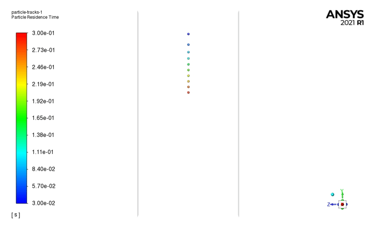
The particle will be injected from a single point as shown in the figure below:
Diesel Spray Ultra-High Injection, Paper Numerical Validation
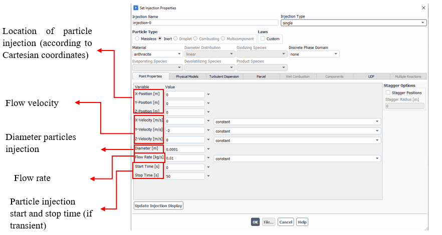
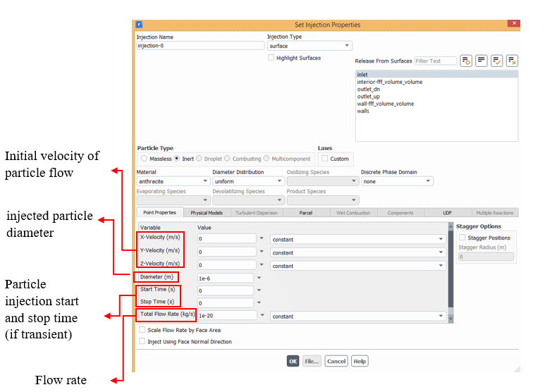
The related specifications are accessible in the point properties tab. The parameters are described below.
The point properties section should specify the injection start and stop times for transient problems and detect transient particles. If we set the value to zero for the start and end of the injection, they are injected only at starting.
Here is an animation of injection from a single point:
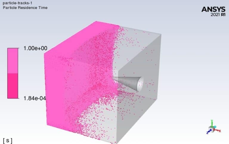
In this animation, the particle residence time is shown that the first injected particle has a longer residence time than the other particles.
Group
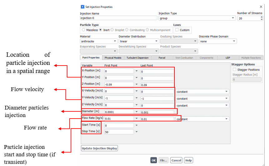
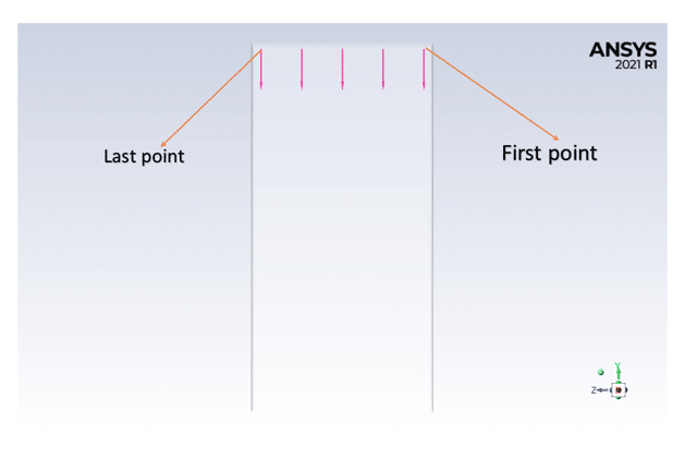
It is used when we want to define a range for the initial conditions. In the properties section, two separate parameters should be set for a line’s first and last point. Then ANSYS Fluent use linear equation to determine the initial condition of N points within. Notice that N introduces the number of streams that the user should specify.
Thus, for example, if your group consists of 5 particle streams and you define a range for the initial x location from 0.2 to 1 meters, the initial x location of each stream is as follows:
- Stream 1: x = 0.2 meters
- Stream 2: x = 0.4 meters
- Stream 3: x = 0.6 meters
- Stream 4: x = 0.8 meters
- Stream 5: x = 1 meters
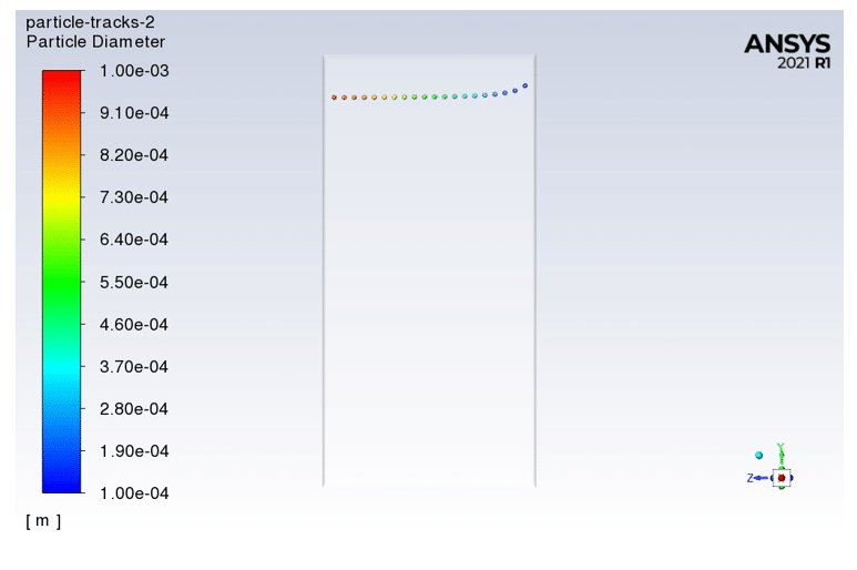
The animations for this mode and the corresponding window changes are given in the following shapes:
The following figure, which has different velocities and is shown based on the residence time, and as we can see, the velocity changes according to the said linear relationship:
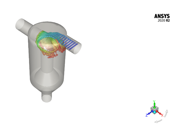
Cyclone with the Motion of Particles
Cone
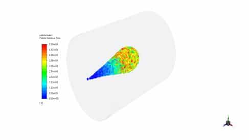
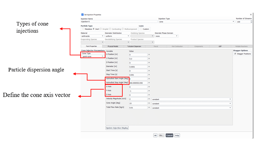
This type is defined for three-dimensional problems and injects the particles like a conical pattern; we can specify its kind from the cone type section. The types of conical shapes are point, hollow, ring, and solid, each explained.
Point type cone, as the name implies, the coordinates of the point that propagates conically are given. The characteristics of this type of injection can be specified as follows:
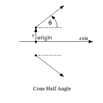
The cone half-angle can be seen in the following figure:
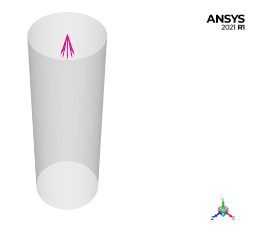
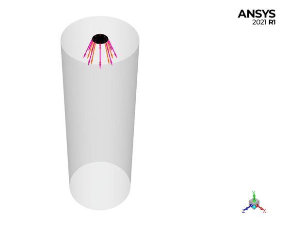
The following figure is an example of a simulation that has already been done.
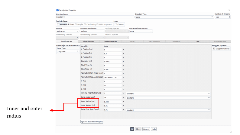
The next type of cone subset is called the ring cone, which, as its name suggests, is published as a ring that has the following specifications:
The following figure is an example of a case study:
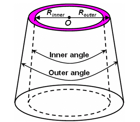
In the following figure, we can see the inner and outer radius:
The animation settings are shown in the following figure, and the animation can be seen below to understand this type of injection better:
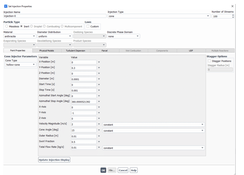
For Solid/Hollow cone type, adjust the velocity magnitude fraction to enter the current’s rotating component in the Swirl Fraction section. The direction of the rotation component is defined using the law to the right of the axis (a negative value for the rotation fraction can be used to reverse the direction of rotation).
The settings for the hollow-cone and solid-cone animations are shown in above Figures. The inputs are fully defined, and below are the animations:
The particles are injected in the form of hollow cones. In contrast to the solid cone, it is clear that the injection of the defined particles is as solid cones.
Surface
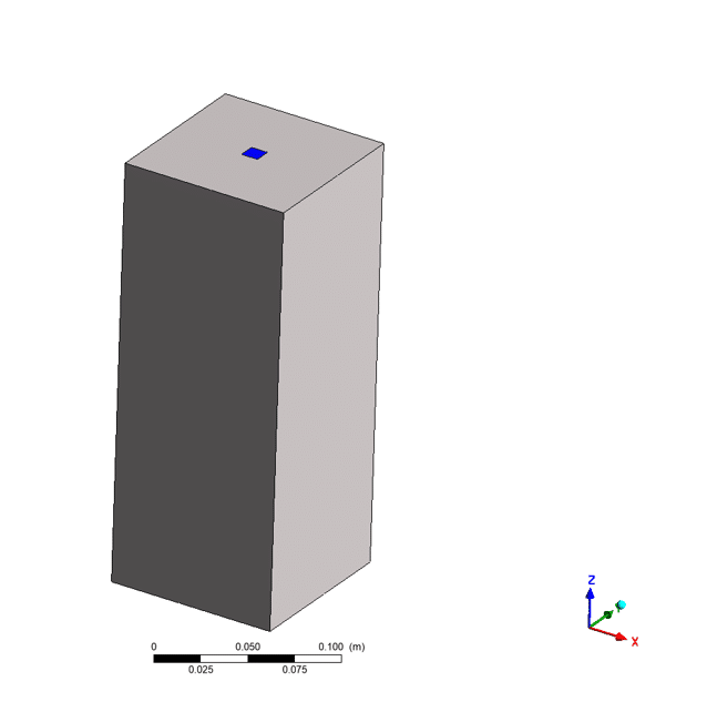
Particle streams are injected from a surface. And is injected from the same area as follows:
Air Freshener Spray in The Restroom
As shown from the figure, for this type of injection to be done well, we must first create a surface according to the current geometry and then adjust the specifications and features of the desired surface as shown below, each of which is described in the parameters:
No coordinates are required in this type of injection. The following is an animation of this previously simulated work:
In addition to simple injections, ANSYS FLUENT offers more complex sprays injections that describe the initial break-up phenomena. For most injections, you must provide the particles’ initial diameter, position, and velocity. However, It uses sprays’ models for predicting droplet size and velocity distribution.
All atomization models use physical atomizer parameters such as diameter orifice and mass flow rate to calculate the initial drop’s size, velocity, and position.
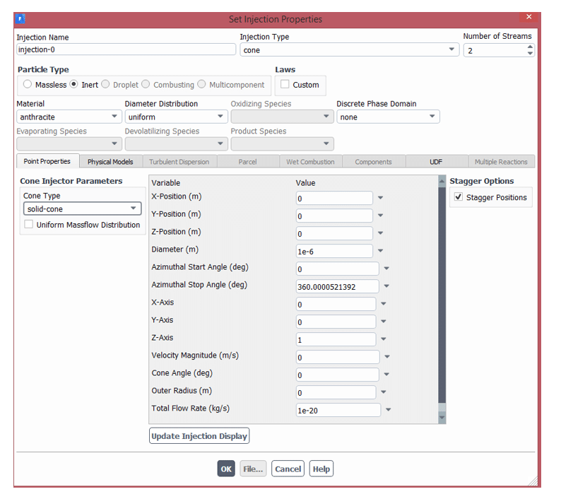
The droplets must be randomly distributed to simulate an atomizer, both spatially through the scattering angle and release time. For other types of injections in ANSYS FLUENT (Non-Atomizer), all droplets are released in fixed paths at the beginning of the time step. Atomizer models use random path selection and staggering to achieve a random distribution.







Nice effort. Please keep it up. Learned a lot.