CFD Project Outsourcing
Outsource your CFD project to the MR CFD simulation engineering team. Our experts are ready to carry out every CFD project in all related engineering fields. Our services include industrial and academic purposes, considering the ANSYS Fluent software's wide range of CFD simulations. By outsourcing your project, you can benefit from MR CFD's primary services, including CFD Consultant, CFD Training, and CFD Simulation.
The project freelancing procedure is as follows:
An official contract will be set based on your project description and details.
As we start your project, you will have access to our Portal to track its progress.
You will receive the project's resource files after you confirm the final report.
Finally, you will receive a comprehensive training video and technical support.
What is Turbomachinery Engineering?
The Design, analysis, and optimization of machines that transfer energy between a fluid and a rotating component are the focus of the field of mechanical engineering known as turbomachinery engineering. This subfield of mechanical engineering is a subset of mechanical engineering. These devices, referred to as Turbomachinery, are utilized in various industries, including power, aerospace, oil and gas, and marine propulsion.
Two categories can be applied to Turbomachinery: turbines and pumps/compressors. Pumps and compressors transmit energy from a rotating component to a fluid, unlike turbines, machines that collect energy from a fluid and transform it into rotational energy. Turbines.
In turbomachinery engineering, the performance evaluation of components, including blades, impellers, and diffusers, is performed using computational fluid dynamics (CFD) and other cutting-edge simulation methods. In addition, it requires the application of experimental methods, such as testing in wind tunnels and the visualization of flow, to evaluate and improve the results gained through simulation.
To successfully design components for Turbomachinery, one needs an in-depth knowledge of fluid dynamics, thermodynamics, and materials science. Engineers working on Turbomachinery have an additional responsibility: they have to take into account the effects of factors like cavitation, erosion, and vibration, all of which can have a substantial influence on the performance and reliability of Turbomachinery.
In general, the engineering of Turbomachinery plays an essential part in the evolution of aerospace and other high-tech industries, as well as the development of energy systems that are both effective and environmentally friendly.
Turbomachines are devices within which the conversion of the total energy of a working medium into mechanical energy and vice versa. Turbomachines are generally divided into two main categories. The first category is used primarily to produce power. It includes, among others, steam turbines, gas turbines, and hydraulic turbines. The primary function of the second category is to increase the total pressure of the working fluid by consuming power. It includes compressors, pumps, and fans. Pumps and turbines have many different types due to their applications; however, the most popular ones in the industry are axial and centrifugal. Optimizing turbomachines is very important in the industry as they consume a lot of energy. Therefore, better performance reduces energy consumption and will help us have a cleaner environment.
How can CFD simulation be applied in Turbomachinery Engineering Industries?
The basic theory behind the Turbomachinery modeling process can be explained through the transmission of the kinetic energy of the fluid flow to the turbomachine itself or vice versa. In the two categories mentioned earlier, for turbomachines like turbines, a flow with specific pressure and momentum hits the blades of the mentioned turbine, transmitting its energy to the turbine, causing its shaft to rotate inside a generator and produce various forms of energy such as electricity. However, in machines like pumps and compressors, electricity is needed to rotate such devices’ impellers to transmit power to fluid for secondary targets.
Creating more effective turbo devices necessitates a deeper comprehension of the performance-influencing elements and their fine-tuning. Today’s computer-aided simulations make it simpler and more affordable than ever to offer solutions for optimizing the Design and performance of Turbomachinery.

To propose alternatives and practical design concepts, simulation-driven Design for Turbomachinery aids in identifying the critical aspects affecting the device performance. The number of prototype testing is drastically decreased, but the number of virtual prototypes is limitless when using virtual computational fluid dynamics simulations. By reducing the number of measurements, CFD enables engineers working on Turbomachinery to develop new products more quickly.
The simulation of computational fluid dynamics (CFD) is a powerful technique that may be utilized in turbomachinery engineering to optimize the Design and performance of various Turbomachinery, such as pumps, compressors, turbines, and fans. CFD is one of the acronyms that stands for computational fluid dynamics. In the industries that deal with turbomachinery engineering, the following are some examples of how CFD simulation might be applied:
– Design optimization: CFD simulation is a tool that can improve the design of turbomachinery components such as impellers, blades, and diffusers. – Design optimization CFD simulation may be used to improve the design of these components. Engineers can find locations of significant pressure drop, recirculation, and turbulence inside these components by simulating the flow behavior inside these components. Once these areas have been identified, the Design can be modified to lessen these areas’ effects and improve the Turbomachinery’s overall performance.
– Prediction of Performance: Computational fluid dynamics (CFD) simulation can be used to make an accurate prediction of the performance of Turbomachinery under a variety of operating situations, including shifts in flow rate, temperature, and pressure, among other variables. Engineers can forecast the Turbomachinery’s performance characteristics by simulating the machine’s flow behavior. These performance characteristics include pressure increase, power consumption, and efficiency. Engineers may then improve the Design to obtain the required performance characteristics.
– Visualization of the Flow: The CFD simulation may be used to see the flow behavior inside turbomachinery components. This can assist engineers in locating areas of flow separation, recirculation, and turbulence in the system. Engineers can obtain insights into the complicated flow phenomena inside turbomachinery components by visualizing the flow behavior. Then they can adjust the Design to lessen the consequences of these complex flow phenomena.
– Analysis of Cavitation: Computational Fluid Dynamics (CFD) simulation can be utilized to analyze the occurrence of cavitation in turbomachinery components, such as pumps and turbines. By simulating the flow behavior inside these components, engineers can detect areas of low pressure that have the potential to trigger the production of cavitation bubbles, which can cause the components to get damaged and degrade their performance. Engineers can increase the overall performance of Turbomachinery by modifying the Design after researching the incidence of cavitation and determining how its impacts can be mitigated.
In general, CFD simulation is a potent tool that may be utilized in the turbomachinery engineering industry to optimize the Design and performance of various Turbomachinery. This can be accomplished through several different approaches. Engineers can acquire insights into the complicated flow behavior inside turbomachinery components using CFD simulation. Then they can adjust the Design to achieve the desired performance levels.
MR CFD services in the Turbomachinery Engineering Industries

- Simulation of different types of Turbines (HAWT, VAWT, Kaplan, Liam, etc.)
- Acoustic analysis and noise reduction of turbomachinery devices
- Investigation of the effect of cavitation inside the turbomachines
- Simulation of different types of pumps and compressors
- Simulation of multi-stage compressors
- Simulation radial blowers
- Simulation cross-flow blowers
- Wind farms Simulation
- …
Two categories can be applied to Turbomachinery: turbines and pumps/compressors.
Compressor
Optimization of a Compressor Cascade
Investigations on the secondary flow phenomena in the region between the corner and sidewalls of axial compressors are carried out with the assistance of a high-speed compressor cascade wind tunnel. Using the MOGA approach, this study aims to improve the efficiency of a compressor cascade. While working on this project, we modeled a sectional compressor cascade in the initial stage.
The problem was optimized for three input and three output parameters, respectively. Input parameters are v_in (also known as the velocity inlet), alpha_degree (also known as the angle of attack), and pitch. Additionally, the drag force, the lift force, and the beta degree are all thought of as output parameters.
This undertaking has an objective function that must be defined so that the drag force must be reduced until it reaches zero, the lift force must be increased until it reaches 0.07, and the beta angle must be reduced until it reaches -12 degrees.
- The problem involves performing a numerical simulation of the optimization of a compressor cascade using the MOGA software with the ANSYS Fluent program.
- Using the SpaceClaim software, we design the three-dimensional model.
- Using the ANSYS Meshing software, we create a mesh of the model, and the total number of elements is 991872.
- We use a Design of Experiment (DOE) to optimize the process.
Pump
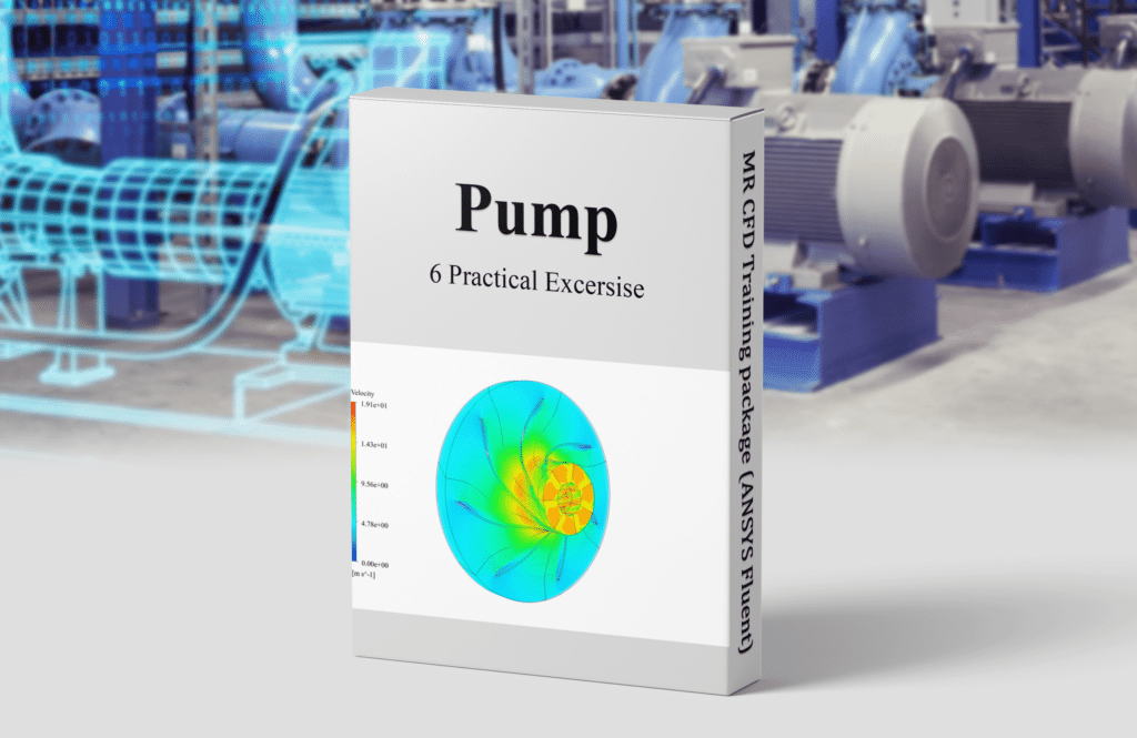
Pump CFD Simulation Training Package
Engineers and students who are interested in learning about the simulation of pumps via the use of computational fluid dynamics (CFD) will find the Pump CFD Simulation Training Package provided by ANSYS Fluent to be a training program that is both thorough and practical in nature.
The training package consists of a series of lectures, tutorials, and exercises that address the theory and practice of pump simulation using ANSYS Fluent. These components are included. The program is broken up into multiple modules, each of which is dedicated to one of the following subject areas:
– Methods of geometry preparation and meshing for use in pump simulations
– Boundary conditions for use in pump simulations
– Modeling of the turbulent flow for use in pump simulations
– Post-processing of the results of pump simulations
Researchers can study the theory and the practical application of pump simulation using ANSYS Fluent by participating in each module’s exercises, tutorials, and lectures. In addition, participants will have access to a specialized support team that will be there to assist and direct them throughout the entirety of the learning process.
In addition, the Pump CFD Simulation Training Package comes with a collection of case studies that illustrate how to apply the concepts learned through pump simulation by using ANSYS Fluent. Case studies like these cover a wide variety of topics, including the following:
– The improvement of centrifugal pumps’ levels of performance
– The occurrence of cavitation in pumps and the implications that it has on performance
– The effect that the Design of the impeller has on the performance of the pump
– The prediction of pump performance in a variety of different operating situations
An overall thorough and hands-on understanding of pump simulation using computational fluid dynamics is provided to students and professionals by ANSYS Fluent through the Pump CFD Simulation Training Package. Students and professionals with this expertise can apply pump simulation techniques to develop efficient and sustainable energy systems. These approaches optimize the Design and performance of pumps, which is essential for developing pumps.
Turbine

The transonic linear turbine cascade is essential to gas turbine engines, which create power and propel aircraft. Several parameters, including the flow conditions, the angle of attack, and the blades’ geometry, determine these cascades’ performance. Numerical analysis can be carried out to investigate the flow field produced by a transonic linear turbine cascade under both Design and off-design situations.
In numerical analysis, one creates a computer model of a transonic linear turbine cascade and then uses computational fluid dynamics (CFD) software to simulate airflow. This is done to get an accurate representation of the flow of air. The simulation outcomes can be used to predict the flow field, pressure distribution, and other aspects of the cascade’s performance.
A paper validation can be carried out to validate the numerical analysis results. This is accomplished by contrasting the simulation outcomes with the experimental data obtained from midspan flow-field measurements on two transonic linear turbine cascades operating under conditions that deviate from their design parameters. Researchers can determine the precision of the numerical analysis by comparing the simulation findings to the data obtained from the experiments.
Utilizing the findings from the numerical analysis and the paper’s validation will allow for improving the performance of transonic linear turbine cascades and optimizing their Design. Researchers can determine the most efficient blade shapes and angles, in addition to the flow conditions that allow for the most significant amount of energy generation, if they can precisely anticipate the flow field and pressure distribution.
To summarize, a numerical analysis can be carried out to analyze the flow field through a transonic linear turbine cascade under both the Design and off-design operating conditions. The numerical analysis results can improve the cascade’s performance and optimize its Design. The numerical analysis can be validated with experimental data from midspan flow field measurements.
Water Turbin
Performance of horizontal axis tidal current turbine by blade configuration
The ANSYS Fluent software models and simulates a water turbine with a horizontal axis for the current project. The outcomes of the CFD simulation are validated by comparing them to the findings of a paper titled “Performance of horizontal axis tidal current turbine by blade configuration.”
There are several elements, one of which is the configuration of the blades, that can influence how well a horizontal-axis tidal current turbine performs. The arrangement of the blades on the rotor refers to their shape, size, and direction in which they are oriented. Alternate configurations of the turbine’s blades have the potential to have a sizeable effect on the machine’s performance parameters, such as the amount of power it generates, its efficiency, and its structural soundness.

Blades with straight, curved, and twisted blades are all popular configurations for horizontal-axis tidal turbine blades. Various criteria, including the speed and direction of the tidal currents, the depth of the water, and the desired power output, will determine the ideal Design. Each arrangement has unique advantages and disadvantages; the optimal configuration will rely on these and other factors.
A horizontal-axis tidal turbine’s performance can be affected by several parameters in addition to the configuration of the blades. These elements include the size and shape of the rotor, the materials used in the turbine’s building, and the generator’s Design.
In conclusion, the performance of a horizontal axis tidal current turbine can be impacted by various factors, one of which is the arrangement of the blades. A paper numerical validation is one method that may be used to study the performance of various blade configurations. This method involves developing a computer model of the turbine and simulating the water flow around the turbine blades. Researchers can improve the turbine’s performance and efficiency by focusing their efforts on optimizing the Design of the blades.
The Darrieus wind turbine: Proposal for a new performance prediction model based on CFD
In a wind turbine known as a vertical-axis wind turbine (VAWT), the main rotor shaft is oriented in a direction that is perpendicular to the ground and transverse to the direction of the wind. As a result of this configuration, VAWTs are available to collect wind energy from all azimuth angles. The Savonius wind turbine, which operates based on the generation of drag, the Darrieus wind turbine, which operates based on the generation of lift, and the H-type wind turbine, are the three varieties of VAWTs.
The H-type wind turbine is similar to the Darrieus design; the only difference is the blades. We will be attempting to test a related study titled “The Darrieus wind turbine: Proposal for a new performance prediction model based on CFD” as part of this project.
The Darrieus wind turbine is a vertical-axis wind turbine comprising vertically curved blades. The Darrieus wind turbine was developed in Germany. When the wind blows across the blades of a wind turbine, it causes the blades to rotate around a central axis, which drives a generator that produces electricity. The performance of a Darrieus wind turbine is susceptible to being influenced by various factors, including the wind speed, the blade angle, and the shape of the blades.
A new performance prediction model based on computational fluid dynamics (CFD) can be proposed as a method for predicting the performance of a Darrieus wind turbine. To accomplish this, a computer model of the turbine must be crafted, and then CFD software must be used to simulate air flow around the blades. The simulation outcomes can be used to predict the turbine’s power production, efficiency, and other performance factors.
A paper validation can be done with ANSYS Fluent, a popular CFD software program, to validate the suggested model for performance prediction. This can be done by using the software. To accomplish this, a comprehensive digital model of the Darrieus wind turbine must be crafted on a computer, and a simulation must be run to determine how different wind speeds and configurations will affect air flow around the blades. The researchers can determine the correctness of the performance prediction model by comparing the simulation outcomes to the experimental data.
The findings of the paper’s validation can be used to enhance the performance prediction model and make the Darrieus wind turbine’s Design as efficient as possible. Researchers can lessen the likelihood of expensive errors and delays during the physical testing phase of the project if they make accurate predictions regarding the performance characteristics of the turbine.
In conclusion, it is possible to present a brand new performance prediction model founded on CFD to forecast the performance of a Darrieus wind turbine. A paper validation can be carried out using ANSYS Fluent to simulate airflow around the blades at various wind speeds and blade configurations to validate the model. This can be done to validate the model. The validation findings can be used to improve the turbine design, thereby lowering the likelihood of errors and minimizing the amount of time lost during the physical testing period.
This paper, “Numerical analysis of lift-based in-pipe turbine for predicting hydropower harnessing the potential in selected water distribution networks for waterlines optimization,” models and simulates the possibility of operating a power plant inside of a pipe by making use of a spherical turbine that is based on the lift. NACA airfoils are used in the manufacturing process of turbine hydrofoil profiles. To achieve this goal, the computer-aided design (CAD) model of a spherical lift turbine based on peak and bottom volume discharge rates has been simulated and analyzed in the program known as ANSYS Fluent. It is possible to get the time series of power outputs by first calculating the time series of changes in discharge.
In recent years, one of the primary concerns of the global community has been the significance of water and energy conservation, and it is anticipated that these issues will soon assume an even greater level of significance. In this context, many technical solutions have been offered to replace pressure relief valves with power generators to securely regulate the pressure of water distribution networks and generate electricity. Utilizing the hydraulic energy efficiency of water, which may be directly transformed into electricity, is one way to improve the energy efficiency of water delivery systems. This method also saves money. This method uses clean energy, which is frequently overlooked in water resources; as a result, energy dependence on the power grid is reduced, as are the expenses of operating the system.

Numerical analysis can be carried out to predict the hydropower harvesting capability of in-pipe turbines in specific water distribution networks for waterline optimization. To accomplish this, a computer model of the in-pipe turbine must be constructed, and then computational fluid dynamics (CFD) software must be utilized to simulate water flow through the turbine. The simulation outcomes can be used to predict the turbine’s power production, efficiency, and other performance factors.
A paper validation can be performed with ANSYS Fluent, a popular CFD software program, to validate the numerical analysis. This can be done by using the software. Creating a comprehensive digital model of the in-pipe turbine and simulating the flow of water through the turbine at various flow rates, and using a variety of turbine types are both required steps in this process. The researchers can determine the accuracy of the numerical analysis by having them contrast the simulation results with the experimental data.
The findings of the numerical analysis and the paper validation can be implemented into improving the layout of water distribution networks to accommodate the installation of in-pipe turbines. Researchers can find the most productive areas for installing these turbines and maximize the amount of energy generated from the water distribution network if they can precisely anticipate the hydropower harnessing the capability of these turbines.
In conclusion, a numerical study of lift-based in-pipe turbines can be carried out to anticipate the hydropower harnessing potential in specific water distribution networks for waterline optimization. A paper validation can be done using ANSYS Fluent to validate the numerical analysis results. This would involve simulating water flow through the turbine for various flow rates and turbine configurations. The analysis findings can be used to enhance the efficiency of the Design and installation of in-pipe turbines, hence increasing the amount of power that can be extracted from the water distribution network.
Wind Turbin
Wind tunnel and numerical study of a small vertical axis wind turbine
The ANSYS Fluent software models the airflow simulation that covers a Vertical Axis Wind Turbine (VAWT) in this particular issue. This CFD project is carried out, and a CFD investigation is carried out.
The simulation was constructed with the help of a reference paper titled “Wind Tunnel and numerical study of a small vertical axis wind turbine.” Its findings are analyzed and evaluated in light of the findings presented in the paper.

Testing in a wind tunnel and numerical analysis are two methods that can be used to investigate the functionality of a small VAWT. To test a wind turbine in a wind tunnel, a physical model of the turbine must be constructed to evaluate its performance in various wind speeds and directions. This can provide beneficial information regarding the turbine’s power output, efficiency, and other performance aspects.
In numerical analysis, a computer model of the VAWT is built, and then computational fluid dynamics (CFD) software is used to simulate the flow of air around the blades. The simulation outcomes can be used to predict the turbine’s power production, efficiency, and other performance factors.
A paper validation can be performed with ANSYS Fluent, a popular CFD software program, to validate the numerical analysis. This can be done by using the software. To accomplish this, a comprehensive computer model of the VAWT needs to be built so that simulations can be run to determine how different wind speeds and blade configurations will affect the flow of air around the blades. Researchers can assess the correctness of the numerical analysis by comparing the simulation results to experimental data gleaned from testing conducted in wind tunnels.
The findings of the testing done in the wind tunnel and the numerical analysis can be utilized to improve the VAWT’s performance and optimize its Design. Researchers can determine the most efficient blade shapes and angles, as well as the ideal wind speeds, for maximum energy generation by adequately estimating the power output and efficiency of the turbine. This allows for the most amount of energy to be generated.
In conclusion, testing in a wind tunnel and numerical analysis are both viable options for evaluating the performance of a vertical-axis wind turbine that is of a smaller scale. The testing and analysis results can be used to optimize the turbine design and increase its performance. Numerical analysis can be confirmed using ANSYS Fluent, and the testing and analysis results can be employed.
HAWT and VAWT Comparison (Mesh Motion and MRF)
In this lesson, we will simulate fluid flow as it goes over two different forms of wind turbines. These wind turbines have vertical axis turbines (VAWT) and horizontal axis turbines (HAWT). Different modeling approaches must be considered when modeling these distinct kinds of wind turbines because the rotational motion of the blades will be different from the global coordinate systems.
The capability of computational fluid dynamics (CFD) to describe fluid flow as it passes through turbomachines is one of the most exciting uses of CFD for engineers. Turbomachines are machines that rotate and transform the kinetic energy of fluid flow into the rotating motion of other machines, such as turbines, or vice versa, in the case of pumps.
The Turbomachinery Training Course has reached its fifth and final episode with the release of this product. As was said before, the VAWT rotates around an axis perpendicular to the flow direction. In contrast, the HAWT are turbomachines that rotate around an axis parallel to the flow direction.
To put it another way, the most accurate way to model the rotational motion of a VAWT would be to use mesh motion and ensure that the rotating zone and the stationary zone are linked with an interface boundary. Additionally, the simulation needs to be carried out transiently to account for the movement of the mesh in a rotating fashion.
However, the user must use the frame motion technique to model HAWTs and assign the desired rotating speed to the turbine blades. They do not need to be concerned with steady or non-steady time studies. Such a strategy would, however, result in the omission of certain time-dependent events. This is the method’s drawback.
Also, it will be explained how a user can define different reports such as lift, drag, and moment for blades of any turbine and acquire various findings and data regarding the motion of turbomachines, both of which would be of great value when creating such structures. In addition to this, it will also be explained how an individual can design such structures.
You will learn how to simulate the rotational motion of turbomachines by employing two of the most well-known models, mesh motion and frame motion, by following the steps in this tutorial. Mesh motion is recommended to create an accurate model of turbomachines with a rotating axis that is not perpendicular to the flow direction (VAWT). However, the frame motion technique is required to simulate rotating structures such as HAWT successfully.
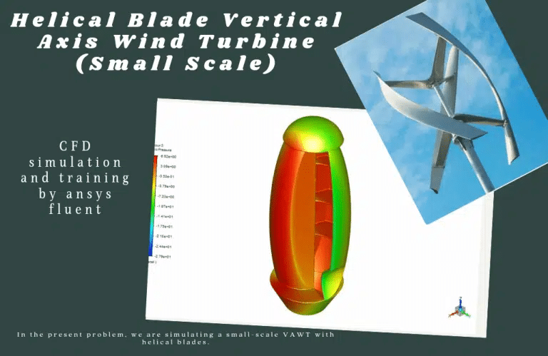
Helical Blade Wind Turbine at five different RPMs
Using the ANSYS Fluent software, the current issue replicates the flow of air that goes over a scaled-down version of a VAWT with helical blades. This CFD project is carried out, and a CFD investigation is carried out.
One of these forms of energy, wind energy, has provided researchers with several options to consider. Compared to the growth rates of other renewable sources, this energy is now expanding at the quickest rate. Wind turbines are the equipment that is utilized in the process of generating energy from the wind.
The kinetic energy of the wind current is converted into the rotor shaft’s rotational energy using a wind turbine device. The issue involves utilizing the ANSYS Fluent software to perform a numerical simulation of a Helical Blade Vertical Axis Wind Turbine. This study examines blade turbines’ TSR (tip speed ratio) at various rotational speeds.
Using the Design Modeler program, we create the three-dimensional model. We mesh the model using the ANSYS Meshing software, and the total number of polyhedral elements comes out at 507457. We run this simulation using an unsteady method known as “transient.” We use the Mesh Motion technique to define rotational motion in the discrete zone around the blades.
MR CFD conducted numerous outsourced simulation projects for industrial and researched Turbomachinery Engineering applications. With several years of experience simulating various problems in various CFD fields using ANSYS Fluent software, MR CFD is ready to offer extensive services of simulation configurations.
Turbomachinery Engineering MR CFD Projects
There are several MR CFD simulation projects in Turbomachinery engineering. Following are some examples of CFD simulation projects. Engineers working on Turbomachinery have an additional responsibility: they have to take into account the effects of factors like cavitation, erosion, acoustic, and vibration, all of which can have a substantial influence on the performance and reliability of Turbomachinery.
Acoustic
Acoustic in a Turbojet Intake Fan
The current problem uses ANSYS Fluent software to simulate the flow of air inside of a turbojet and analyze the acoustic wave as well as the sound that is generated inside of this turbojet. The acoustic model is utilized by the program to perform research on sound or acoustic waves.
- The challenge employs the ANSYS Fluent software to do a numerical simulation of acoustic phenomena in a turbojet intake fan.
- Using the Design Modeler program, we create the three-dimensional model.
- After running the model through the ANSYS Meshing software, we see the total number of elements is 3723166.
- When analyzing compressible flow, we make use of a solver that is density-based.
- To characterize the rotating movement, we make use of something called the Frame Motion, or MRF.
- To define the Acoustic model, we use the Broadband Noise Sources model.
FW-H and Broadband Noise Comparison on a HAWT
In this tutorial, we will investigate the differences between two prominent models for predicting acoustics in fluids, including Ffowcs Williams-Hawkings (FW-H) and Broadband noise model, to investigate the noise and sound generation due to the rotating motion of a horizontal axis wind turbine (HAWT). This will be done to investigate the noise and sound generation caused by a horizontal axis wind turbine (HAWT).
Due to the CFD’s internal workflow for calculating pressure and viscous tensions created by the medium flowing over various solid structures, one of the most exciting applications of CFD for engineers is its capability to anticipate sound waves and sounds. This is one of the reasons it is one of the most intriguing uses of CFD. This skill has a wide variety of applications and uses.
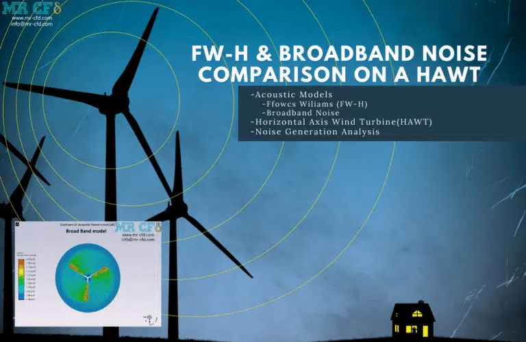
When the FW-H model is active, the user must explicitly describe the source and receiver of sound waves. This is relevant to modeling the noise generation that wind turbines are responsible for.
Although the user can define any source or receiver in the computational domain when using the FW-H model, the model’s limitation is that the user can only extract specific kinds of results, such as FFT analyses of sound waves formed in the domain. This is the model’s primary shortcoming.
In contrast to the FW-H model, in which the user was required to explicitly identify receivers, the Broadband noise model allows every point inside the domain to function as a receiver. As a result, this model has an advantage over the FW-H model in that it can extract a wide variety of graphical outputs and data, ranging from the influence of shear on the formation of acoustic waves to the sound pressure level at any given position within the domain.
You will learn how to use two of the most well-known models for predicting the generation of acoustic waves within a computational domain containing a wind turbine with a horizontal axis by following the steps outlined in this lesson. Strong sound waves will be produced as a result of the rotational motion of the HAWT as well as the airflow that passes over such a structure. These sound waves could potentially be detrimental to human hearing at close range.
As a result, to examine such a phenomenon, we have used acoustic models within ANSYS Fluent. These models include FW-H and Broad band noise. Several sets of outcomes and pieces of data demonstrate the capabilities, advantages, and disadvantages that one model may have over another.
Cavitation
Cavitation in a Cross-Flow Turbine
In this project, which has been carried out using the computational fluid dynamics (CFD) numerical simulation approach provided by the Ansys Fluent software, cavitation in a cross-flow turbine has been studied. With most turbines, the fluid flow is either axial or radial; however, the flow is transverse with this turbine. This particular kind of turbine rotates slowly and is used in situations requiring a low head and a large flow.
The majority of this project has been completed in three distinct stages. In the first scenario, there is no airfoil present, but in the second scenario, there is an airfoil present at the entrance to prevent cavitation. In the third scenario, the airfoil’s angle is increased by 15 degrees in the direction of a clockwise rotation compared to the second scenario.
Case 1
The cavitation phenomenon is a phenomenon that takes place in turbo vehicles and in blades that are whirling. Corrosion occurs on the surfaces of the edges as a result of this process, which is particularly harmful. Within the context of this simulation, it is evident, based on the pressure contour, that in the appropriate portion of the blades. As a result of the pressure being low and being lower than the vapor pressure at that temperature, the cavitation phenomenon occurs, and the phase transition takes place. To put it another way, the suction created by the edges moving from the bottom to the top of the blade is the cause of the pressure drop on the right side of the blade.
Case 2
example 2: Based on the information in the first example, an airfoil has been installed in the turbine’s inlet to prevent cavitation. This design style can prevent cavitation since it forms on the airfoil, which can serve a protective function.
Case 3
In the previous scenario, an airfoil was installed at the inlet of the turbine to prevent cavitation. Compared to the most recent scenario, the airfoil’s angle was shifted 15 degrees in the clockwise direction. This step’s objective is to explore the influence that varying the airfoil angle has on the intensity of the effect. Cavitation
It can be claimed that the rotation of the airfoil clock has been helpful for us because the contours that were taken from the volume fraction of the second phase show that the amount of cavitation is slightly less than what it was in the previous scenario.
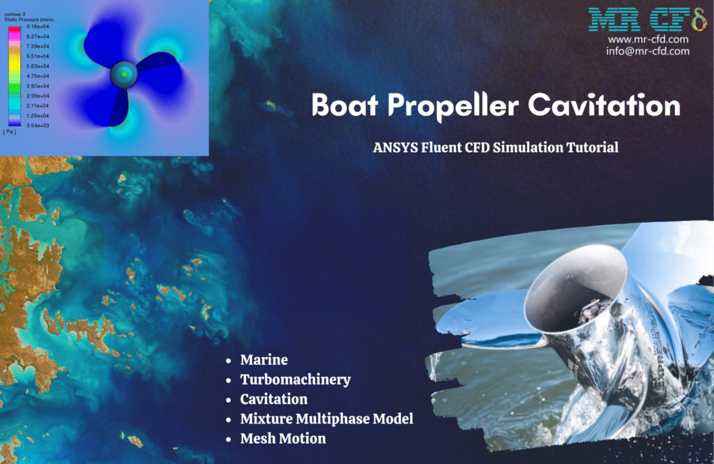
MR CFD is a significant provider of computational fluid dynamics (CFD) services and training, and they offer a lesson called the Boat Propeller Cavitation CFD Simulation lesson. This tutorial is an in-depth, step-by-step guide. Students and professionals in the field of marine engineering who are interested in learning about the cavitation phenomenon in boat propellers and would want to do it with the assistance of ANSYS Fluent are the target audience for this tutorial.
The tutorial consists of a series of lectures, tutorials, and exercises that address the theory and practice of cavitation simulation in boat propellers using ANSYS Fluent. The material is presented in the form of a tutorial. The tutorial is broken up into several different parts, each of which focuses on one of the following subjects:
- ANSYS’s Intro to Cavitation in Boat Propellers
- Introduction to Cavitation
- The capabilities of the Fluent software for cavitation simulation;
- meshing approaches for the modeling of boat propellers;
- boundary conditions for the cavitation simulation of boat propellers
- Post-processing of cavitation simulation results
- Turbulence modeling for cavitation simulation of boat propellers
- Post-processing of cavitation simulation results
Researchers can study the theory and practice of cavitation simulation in boat propellers by utilizing ANSYS Fluent by participating in each module’s exercises, tutorials, and lectures. In addition, the tutorial grants users access to a specialized support team that is available to offer aid and direction at any point during the learning process.
– The beginnings of cavitation in boat propellers and how it develops over time
– The effect that boat propeller design has on the cavitation phenomena
– The ability to predict how well boat propellers will operate when cavitation is present
– The reduction of cavitation through the optimization of the Design of boat propellers
MR CFD’s Boat Propeller Cavitation CFD Simulation Tutorial is designed to give students and professionals a complete and practical understanding of cavitation simulation in boat propellers using ANSYS Fluent. The tutorial can be found here. Students and experts alike can use this information to apply cavitation simulation techniques to improve the Design and performance of boat propellers, which is vital for developing efficient and sustainable marine transportation.
Cavitation Flow Through an Axial Inducer
This simulation uses the ANSYS Fluent program to examine cavitation flow through an axial inducer. This CFD project is carried out, and a CFD investigation is carried out. One of the occurrences known as cavitation occurs when vapor bubbles are generated in a region of a fluid in which the pressure is lower than in other parts of the fluid. There is a common misunderstanding that the only reason for this phenomenon and the development of steam bubbles is because the pressure of the liquid reaches the pressure of the vapor.
On the other hand, this phenomenon is brought about by various other factors and conditions. For instance, speed is one of the valuable characteristics that can be utilized in producing this phenomenon. The process known as cavitation can contribute to various issues, including corrosion. The water pump shows clear signs of corrosion throughout its entirety.
This phenomenon can be identified based on the sound it produces and the mechanical vibration it causes. One can take many approaches to lessen the likelihood of this happening. One of the most straightforward approaches is to shorten the distance separating the pump and the storage tank to boost the pump’s inlet pressure.
One other strategy involves minimizing both the pressure drop and the turbulent flow. Today, as a result of the growth of the sector, there is an increased demand for pumps that are both more compact and operate at faster rates. As a result, it is essential to enhance the suction performance of the pump impellers.
Inducers are vital components in front of the pump’s primary impeller to increase the pump’s suction performance while maintaining the same speed as the impeller. The performance of the pump’s suction can be improved thanks to the inducer, which can boost the pressure applied to the pump’s impellers.
Cavitation is a phenomenon that should be considered while designing pumps because it is one of the most fundamental phenomena. Inducers are used in pumps for various reasons, but one of the most essential is to cut down on cavitation.
Cavitation in a Radial Flow Pump
Using ANSYS Fluent as its platform, this tool simulates the cavitation phenomenon within a radial flow pump. This CFD project is carried out, and a CFD investigation is carried out. This pump is a centrifugal pump, also known as a radial flow pump. Because of this, the desired fluid enters the pump perpendicular to the central axis and exits the pump in a radial direction to the input path. These are the most prevalent among pumps and are typically used to generate high pressures while only moving a small amount of fluid at a time.
When the pressure of a liquid drops below the vapor pressure of that liquid while the temperature remains the same, a phenomenon known as cavitation occurs. In this instance, the fluid changes state from liquid to vapor, which results in the formation of a bubble. Cavitation is the name given to this process.
Now, if these bubbles are moved to the high-pressure regions of the pump, they will pop due to the increased pressure—this bubble bursting results in a vacuum in the surrounding area. As a direct consequence of this vacuum, the liquid in the area around the bubble travels at an extremely high rate and pressure in the direction of the space.
Vibration
Fluid-Structure Interaction over HAWT Turbine
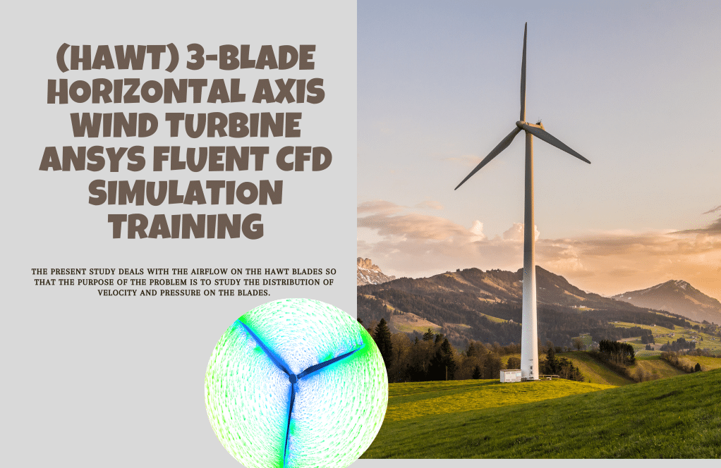
This study aims to investigate the fluid-structure interaction that occurs over a HAWT turbine. In this simulation, the turbine is heated by a flow moving at 25 meters per second while the turbine rotates at 12 revolutions per minute. The FSI procedure was conducted in a one-way direction, during which we studied the impact of the fluid on the structure. The overall distortion was around 0.2 meters at the end of the blades. Additionally, both the bending stress and strain have been investigated and assessed.
MR CFD is a significant provider of computational fluid dynamics (CFD) services and training, and one of the products that they give to their customers is a learning simulation called the Fluid-Structure Interaction (FSI) over Horizontal Axis Wind Turbine (HAWT) CFD Simulation. This educational product was developed for students and professionals in turbomachinery engineering interested in learning about the FSI simulation of HAWT turbines using ANSYS Fluent. The target audience for this product includes both students and professionals.
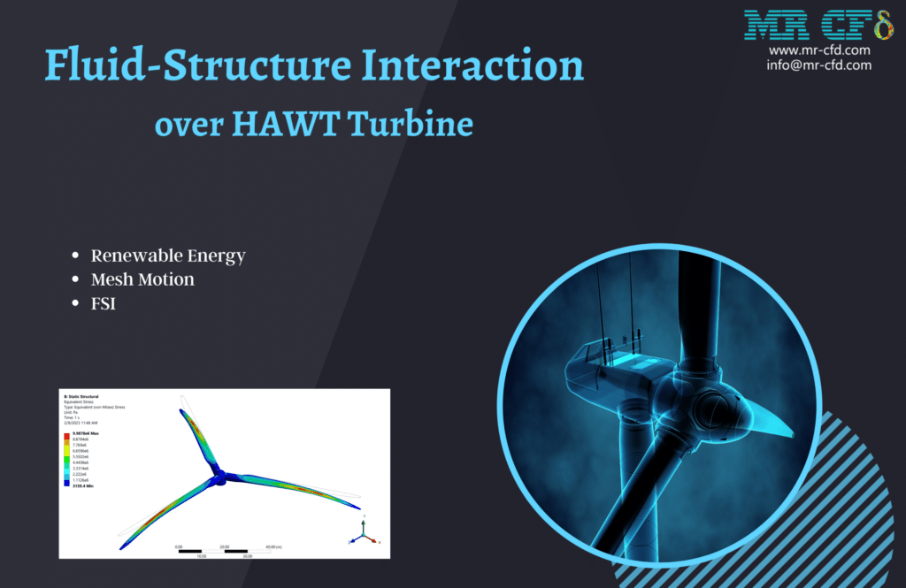
The educational product also features a collection of case studies illustrating how ANSYS Fluent can perform FSI simulations on HAWT turbines. These case studies discuss a wide variety of topics, including the following:
– Aerodynamic performance of HAWT turbines under a variety of wind conditions – Blade deformation and vibration in HAWT turbines
– The HAWT turbines’ structural integrity in the face of extremely high wind loads
– The application of FSI modeling in the optimization of the HAWT turbine design
Fluid-Structure Interaction over HAWT Turbine CFD Simulation is a learning product that MR CFD gives. It aims to equip students and professionals with a complete and practical understanding of the FSI simulation of HAWT turbines using ANSYS Fluent. Students and professionals can use this information to apply FSI simulation techniques to optimize the Design and performance of HAWT turbines, which is vital for developing sustainable energy sources. FSI simulation methodologies can be found here.
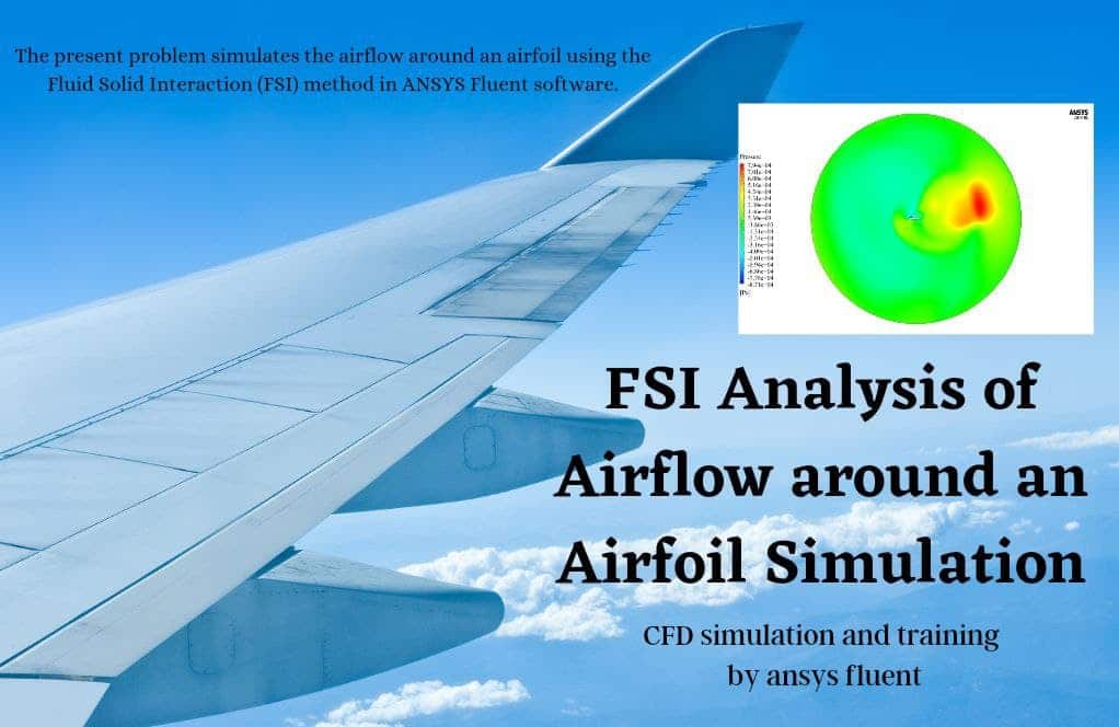
In this study, an unsteady computational fluid dynamics (CFD) simulation was performed using the ANSYS Fluent program to analyze water flow around a vertical water turbine. It is hypothesized that the passage of the fluid through the turbine blades exerts a force on the body of the turbine, which in turn causes the body of the blades to either deform or resize as a result of the force. This is the situation that we are dealing with at the moment. As a result, the current issue calls for two different liquid and solid solutions simultaneously; hence, the FSI approach and the coupling between the fluid flow and the Transient Structural are utilized to solve the issue.
Turbomachinery Industrial Companies
Many industrial companies have made it their area of expertise to be Turbomachinery’s design, production, and upkeep. The following are some examples of industrial enterprises specializing in Turbomachinery:
– General Electric (GE): General Electric is a worldwide conglomerate that manufactures various products, such as Turbomachinery for power generation, oil and gas, and aviation industries.
– Siemens: Siemens is a multinational technological business that manufactures various goods, such as Turbomachinery, for use in the power generating, oil and gas, and marine industries.
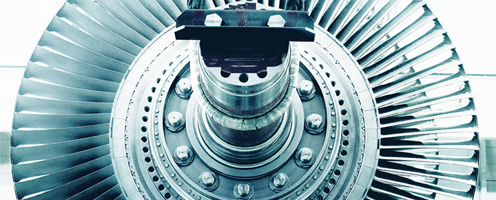
– Baker Hughes: Baker Hughes is an American industrial service firm that serves the oil and gas sector by providing various goods and services, including turbomachinery equipment and maintenance services. Baker Hughes is headquartered in Houston, Texas.
– Sulzer: Sulzer is a Swiss firm specializing in industrial engineering and production. They make various goods, such as Turbomachinery, for various industries, including water, oil and gas, and power generation.
– Kawasaki Heavy Industries (KHI): KHI is a Japanese multinational engineering business that produces a wide range of products, some of which include Turbomachinery for use in the power generating, maritime, and aerospace industries.
– MAN Energy Solutions: MAN Energy Solutions is a German international engineering firm that manufactures various products, such as Turbomachinery for power generation, oil and gas, and marine industries. MAN Energy Solutions is headquartered in Munich, Germany.
These businesses and many others play an essential part in the turbomachinery industry by conceptualizing, manufacturing, and maintaining the machinery utilized in various industries.
MR CFD Industrial Experience in the Turbomachinery Field
Following is an example of a Turbomachinery industrial project recently simulated and analyzed by MR CFD in cooperation with related companies.
Pelton Wheel Turbine
A form of impulse turbine known as a Pelton wheel turbine is typically used in hydroelectric power facilities where it is utilized to generate energy. Lester Allan Pelton created it. Hence his name was given to the device. The generator comprises a collection of buckets or cups placed in a circle around the rim of a wheel. The water is poured onto the cups, which makes the wheel rotate. This motion, in turn, drives a generator, which results in the production of power.
To improve the efficiency of the Design and operation of Pelton wheel turbines, numerical studies are frequently carried out. Simulations using computational fluid dynamics (CFD) can model water flow through the turbine and estimate the performance of various design configurations. This can be done to improve the turbine’s efficiency. These simulations can also be used to locate areas of excessive stress or turbulence that may eventually result in the breakdown of mechanical components.
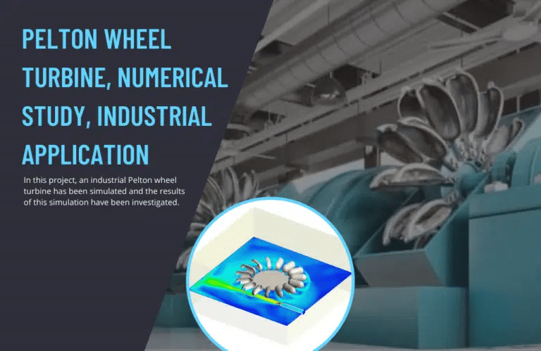
In conclusion, Pelton wheel turbines are essential to generating hydroelectric power and are widely used in various industrial settings. The Design and performance of these turbines are optimized through computational studies, and they are particularly well-suited for use in geographically isolated or mountainous places.
This article discusses a well-known type of turbine called an impact generator. The Pelton turbine is the only impact hydraulic turbine currently being utilized. The second law of Newton states that the energy generation by this turbine requires the employment of a fluid jet. The runner is rotated because this turbine is struck by a pressurized water nozzle tangential to the bucket linked to the runner.
Because each bucket is part of a pair, the force is balanced, and the momentum is transferred smoothly and effectively. There is a range of sizes available for the pellets. Smaller sizes are employed to generate energy in more remote places, whereas larger sizes are utilized in the construction of dams because these turbines were constructed expressly for larger heads.
The ANSYS Fluent software is used to model a miniature Pelton turbine for this project. The turbine has a diameter of 300 millimeters and 15 buckets. In addition to that, one of the goals of this study is to determine the amount of torque generated by this turbine.
MR CFD conducted numerous outsourced CFD simulation projects for industrial companies and research in Turbomachinery Engineering applications. With several years of experience simulating various problems in various CFD fields using ANSYS Fluent software, the MR CFD is ready to offer extensive CFD Simulation, Training, and Consultation services.
You may find the Learning Products in the Turbomachinery Engineering CFD simulation category in Training Shop. You can also benefit from Turbomachinery Engineering Training Packages appropriate for Beginner, Intermediate, Advanced, and Expert users of ANSYS Fluent. Also, MR CFD is presenting the most comprehensive Turbomachinery Engineering Training Course for all ANSYS Fluent users from Beginner to Experts.
Our services are not limited to the mentioned subjects. The MR CFD is ready to undertake different and challenging projects in the Turbomachinery Engineering modeling field ordered by our customers. We even carry out CFD simulations for any abstract or concept Design you have to turn them into reality and even help you reach the best strategy for what you may have imagined. You can benefit from MR CFD expert Consultation for free and then Outsource your Industrial and Academic CFD project to be simulated and trained.
By outsourcing your project to MR CFD as a CFD simulation consultant, you will not only receive the related project’s resource files (Geometry, Mesh, Case & Data, …), but also you will be provided with an extensive tutorial video demonstrating how you can create the geometry, mesh, and define the needed settings(pre-processing, processing, and post-processing) in the ANSYS Fluent software. Additionally, post-technical support is available to clarify issues and ambiguities.
