CFD Project Outsourcing
Outsource your CFD project to the MR CFD simulation engineering team. Our experts are ready to carry out every CFD project in all related engineering fields. Our services include industrial and academic purposes, considering the ANSYS Fluent software's wide range of CFD simulations. By outsourcing your project, you can benefit from MR CFD's primary services, including CFD Consultant, CFD Training, and CFD Simulation.
The project freelancing procedure is as follows:
An official contract will be set based on your project description and details.
As we start your project, you will have access to our Portal to track its progress.
You will receive the project's resource files after you confirm the final report.
Finally, you will receive a comprehensive training video and technical support.
What is Combustion?
Combustion is a chemical process in which a substance reacts rapidly with oxygen and gives off heat. The original substance is called the fuel, and the source of oxygen is called the oxidizer. The fuel can be a solid, liquid, or gas. The oxidizer, likewise, could be a solid, liquid, or gas but is usually a gas (air). New chemical substances are created from the fuel and the oxidizer during Combustion. These substances are called exhaust. Most of the exhaust comes from chemical combinations of fuel and oxygen. When a hydrogen-carbon-based fuel (like gasoline) burns, the exhaust includes water (hydrogen + oxygen) and carbon dioxide (carbon + oxygen). But the exhaust can also include chemical combinations from the oxidizer alone. If the gasoline is burned in the air, containing 21% oxygen and 78% nitrogen, the exhaust can also include nitrous oxides (NOX, nitrogen + oxygen). The exhaust temperature is high because of the heat transferred to the exhaust during Combustion. Because of the high temperatures, exhaust usually occurs as a gas, but there can be liquid or solid exhaust products. Soot, for example, is a form of solid exhaust that occurs in some combustion processes.
Heat is generated when the fuel and oxidizer are turned into exhaust products during Combustion. Interestingly, some source of heat is also necessary to start Combustion. Gasoline and air are in your automobile fuel tank, but Combustion does not occur because there is no heat source. Since heat is both required to start Combustion and is itself a product of Combustion, we can see why Combustion occurs rapidly. Also, once Combustion gets started, we don’t have to provide the heat source because the heat of Combustion will keep things going. We don’t have to keep lighting a campfire. It just keeps burning.
Three things must be present for the Combustion: fuel to be burned, a source of oxygen, and heat. As a result of Combustion, exhausts are created, and heat is released. You can control or stop the combustion process by controlling the amount of fuel available, the amount of oxygen available, or the heat source.
The release of heat and light results from the chemical reaction known as Combustion, which occurs when a fuel and an oxidant, typically oxygen, are brought together. This is known as an exothermic reaction, which releases heat and light as forms of energy. The burning of fossil fuels for the creation of energy, the Combustion of wood for cooking and heating, and the Combustion of fuels in internal combustion engines for transportation are all examples of Combustion, a fundamental process in various industrial and natural processes.
During the combustion process, the fuel combines with the oxygen in the air to produce carbon dioxide, water vapor, and sometimes other byproducts, the exact nature of which is determined by the type of fuel being burned and the conditions under which the reaction occurs. The flame is the visible expression of the heat and light emitted as a byproduct of the reaction, and it is often the defining characteristic of the reaction. The flame’s temperature can reach several thousand degrees Celsius depending on the type of fuel being used and the conditions under which the reaction is taking place.
The process of Combustion is essential to a significant number of biological and industrial activities, but it also has consequences for the surrounding environment. Because the emission of carbon dioxide and other byproducts of Combustion can contribute to climate change and other forms of air pollution, there is an increasing interest in developing combustion technologies that are cleaner and more efficient to lessen the negative impact of combustion processes on the environment.
How can CFD simulation be applied in Combustion Engineering Industries?
Simulation using CFD (Computer Fluid Dynamics) is a potent instrument with many potential applications within the combustion engineering industry. The following is a list of potential applications for the CFD simulation:
The Design of combustion systems
Computational fluid dynamics (CFD) simulation can be utilized in designing and optimizing combustion systems like burners and boilers. Engineers can improve system performance, efficiency, and emissions control by optimizing the Design of these systems by using computer simulations that model the flow of fuel, air, and the products of Combustion.
Combustion Chamber Performance Optimization with DOE
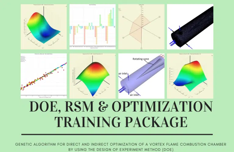
Following that, we will walk you through optimizing the combustion chamber’s input parameters based on the data generated for RSM analysis. In the second part, we will demonstrate how to perform direct optimization by first generating the design points required for the optimization process, and then, after defining desired target(s) (such as maximizing the value of heat generation rate while minimizing the amount of formed pollution), the software will begin the optimization process. At that point, it will present you with the best three candidate points.
Analysis of combustion processes
CFD simulation can analyze Combustion processes in-depth, including generating pollutants such as NOx and particulate matter. This type of analysis can be carried out in several different ways. Engineers can better grasp the factors influencing combustion efficiency and emissions by simulating the chemical reactions and transport processes during Combustion. This allows for the engineers to obtain a better understanding of the factors.
Using the ANSYS Fluent software, this Project is a computational fluid dynamics (CFD) simulation of Combustion in a bluff-body mild burner. A burner is a piece of equipment that combines a specific quantity of air with fuel in a contained area. This process, known as Combustion, transforms the energy stored in the fuel into heat energy while producing some gas as a byproduct of the reaction. Convection and radiation are the two strategies utilized to bring the flame produced in the burner to the inside of the chamber. As a result, the Radiation (DO) model ought to be utilized in the currently utilized model. The Species Transport model is also utilized because the combustion process occurs within the chamber.
This burner sprays fuel into the chamber via a specialized jet intake. At the same time, gas flows symmetrically into the chamber from four different directions. This causes the fuel and air to combine to generate a flame. In addition, the working system of the enclosure is that the gas flow path inside the chamber is cyclic, and a portion of it departs the exhaust section. In contrast, another portion returns to the enclosure from the same circular channel. This is how the enclosure maintains its temperature and pressure.
Flame Stabilization
Computational Fluid Dynamics (CFD) simulation is a tool that may be used to investigate the mechanisms behind flame stabilization in combustion systems. Engineers can determine the factors that contribute to flame stability and build new burner designs that are more stable and efficient by modeling the flow and combustion processes that occur in various types of burners. This allows the engineers to identify the components that contribute to flame stability.
Pollution control
Computational fluid dynamics (CFD) simulation can be applied to the investigation of the efficacy of various pollution control methods, including selective catalytic reduction (SCR) and exhaust gas recirculation (EGR). Engineers can gain better control of emissions by optimizing the Design and operation of these systems by simulating their flow and chemical reactions.
Combustion Pollutants Prediction Training Package
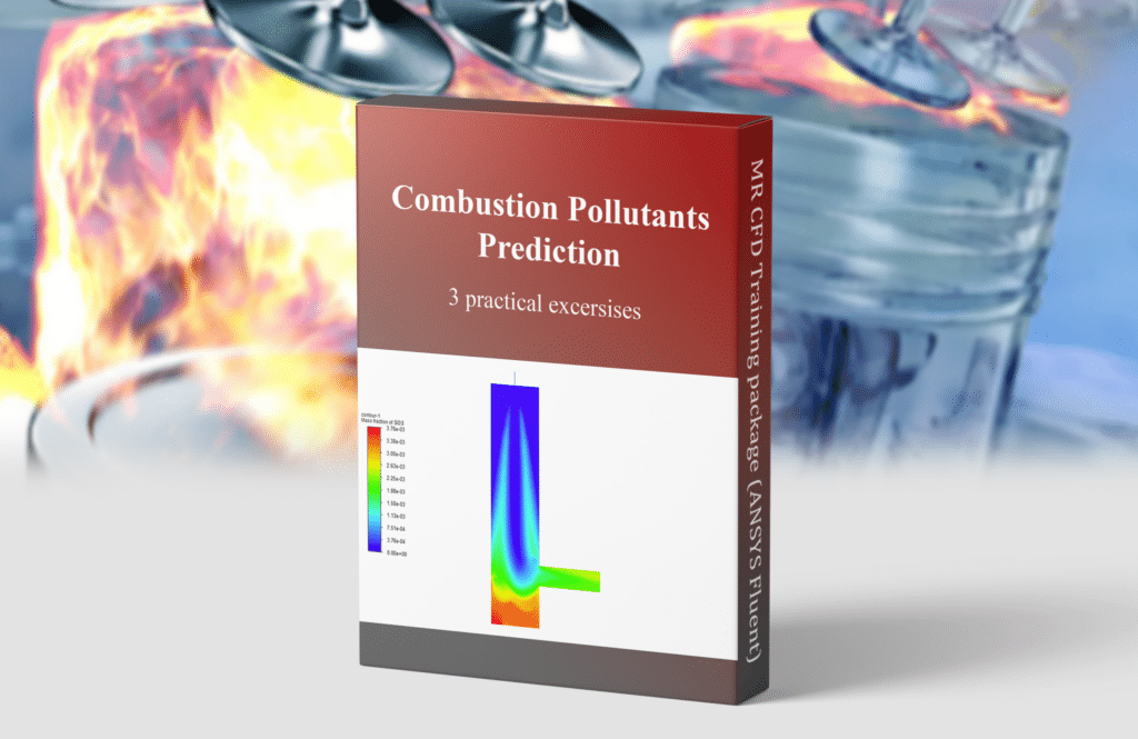
The package also contains a comprehensive set of tools, such as tutorials, case studies, and reference materials, that are intended to assist users in gaining an understanding of the foundations of combustion pollutant prediction. The resources are intended to assist users in developing their ability to analyze the results of their simulations and grasp the underlying physics and chemistry of combustion pollutant prediction.
Simulations of computational fluid dynamics (CFD) can be used to provide predictions about the pollutants that Combustion produces. CFD simulations represent the flow of air and combustion gases within an engine or any other type of combustion system. The simulations can predict the pollutants created due to the combustion process. These pollutants include carbon monoxide, nitrogen oxides, and particulate matter. The simulations can also be used to improve the architecture of the combustion system, which will ultimately help to lower the amount of pollutants produced.
Analysis of fire and explosions
Computational fluid dynamics (CFD) simulation can be used to investigate the risk of fire and explosion in manufacturing processes. Engineers can detect possible dangers and devise solutions to mitigate them by simulating the flow and combustion processes in various settings.
Fire and Smoke in a Factory Building
Using the ANSYS Fluent software, the current issue replicates the combustion reaction (Fire & Smoke) of a pressure tank inside a plant. The computational zone is represented as a factory in this concept. Within this area, models of various components, such as tanks, plates, boxes, and others, have been created. When a leak occurs in a pressurized tank of a cylindrical shape, combustible methane gas escapes into the environment outside of the tank. When this occurs, a reaction occurs due to methane coming into touch with free-flowing ambient air.
The purpose of this research is to explore, over time, the behavior of the flame of Combustion as well as the path of smoke emission from Combustion. Therefore, a time-dependent approach is taken to carry out this simulation. To complete this simulation, there are two steps. The first step consisted only of an investigation into the escape of methane from the tank into the surrounding atmosphere.
In this scenario, methane is slowly let go into the inner area over the course of some amount of time. The second stage involves the escaping gas reacting with the surrounding air, sparking ignition. Flame, smoke, and sometimes even carbon dioxide gas can be created as a byproduct of the combustion reaction. In the first phase, defining the chemical reaction is unnecessary; only air and methane are defined while the reaction is prevented.
The air and methane contained within the tank are subject to pressure inside the facility. The groove at the top of the tank is modeled as the leakage center, and establishing a higher beginning pressure for the methane contained within the tank while it is under pressure causes the methane to leak out into the surrounding environment.
Once the release has been completed in its entirety, it is time to determine the combustion reaction that will take place between methane and free air. Therefore, stoichiometric coefficients can establish a chemical reaction in which methane and oxygen are the reactants, and carbon dioxide and vapor are the products.
In addition, a spark is created in the groove area of the tank so that the combustion process may take place more effectively. CFD modeling is a beneficial tool for the combustion engineering industry because it offers insights into the intricate flow and combustion processes within these systems and assists in optimizing the Design and operation of these systems for improved performance, efficiency, and control of emissions.
MR CFD services in the Combustion Engineering Industries
With several years of experience simulating various problems in various CFD fields using ANSYS Fluent software, the MR-CFD team is ready to offer extensive modeling, meshing, and simulation services. CFD Simulation Services for Combustion are categorized as follows:
- Combustion in annular, can and double annular combustor
- CFD simulation of CH4 (methane) combustion in a vortex flame chamber
- Simulation of two and four-stroke engines in internal combustion engines using dynamic mesh method
- Combustion and explosion of methane in a circular tube
- Combustion of Keresan in a gas turbine combustion chamber
- Methane combustion in a vortex flame chamber
- …
The theory behind the combustion process can be explained through two significant fields of Mechanical Engineering; Mass transfer and heat transfer. As was mentioned in the previous paragraph, Combustion is the product of fuel and air burning in the presence of heat. Mixing fuel and air and generating new chemical species can be solved using the mass transfer equation coupled with Navier-stokes equations. The heat generated by this process and its effect on the ambient medium can also be analyzed using the coupled energy and Navier-stokes equations.
The combustion process in ANSYS FLUENT software can be simulated using the species module. The three frequently used models that can be exploited to simulate the Combustion in this module are Premixed Combustion, non-premixed Combustion, and partially premixed Combustion.
Premixed Combustion
Premixed Combustion Training Course
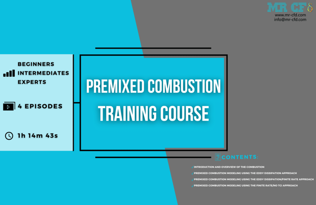
Hello, and thank you for enrolling in our comprehensive training course on premixed Combustion! The ANSYS Fluent CFD software will be used throughout this course to provide a comprehensive understanding of premixed combustion modeling. In this class, we will go over several different simulation approaches, beginning with an introduction to combustion concepts, then moving on to topics such as premixed combustion eddy dissipation, premixed combustion eddy dissipation/finite rate model simulation, and premixed Combustion finite rate/no TCI simulation. All of these topics will be covered in detail.
Lesson 1
The first thing you will learn in this course is a comprehensive introduction to Combustion, followed by a review of the various simulation approaches and models accessible in ANSYS Fluent. This section is further divided into the following subsections:
- A preliminary discussion followed by an analysis of the Combustion
- A brief introduction to the various applications of Combustion
- A survey of the several branches of physics that are relevant to Combustion
- The physics of Combustion o Combustion from premixed fuel and air
o Premixed Combustion
o Non-premixed Combustion
o Partially premixed Combustion
- Summary of different fast and finite rate chemistry models implemented in ANSYS Fluent
Lesson 2
Lesson 2 of the ANSYS Fluent course, provides a synopsis of the many fast and finite-rate chemical models deployed.
In this lesson, we will investigate the Combustion inside a combustion chamber while carrying out a straightforward project. This will allow us to discuss premixed combustion modeling using the Eddy Dissipation method. This section is further divided into the following subsections:
- How to define the stoichiometric mass fractions for fuel and air in a chemical reaction
- Obtaining graphical outlines by extraction
- The process of data analysis
Lesson 3
In this lesson, we will discuss the modeling of premixed Combustion utilizing the Eddy Dissipation/Finite Rate technique. We will then study pollution formation by carrying out a straightforward project investigating the Combustion within a combustion chamber. This section is further divided into the following subsections:
- Axisymmetric combustion chamber modeling
- NOx formation
o thermal NOx
o prompt NOx
- Soot formation
o one step
o two-step
- Decoupled detailed chemistry
- Reactor network
- Extracting graphical contours
- Analyzing the data
Lesson 4
In this lesson, we will investigate the Combustion taking place inside a boiler fire tube to carry out a straightforward project that will serve as the basis for our discussion of the Premixed Combustion modeling utilizing the Finite rate/No TCI technique. This section is further divided into the following subsections:
- The mechanism for importing checks and balances
- Unwind with the help of the chemical equilibrium problem solver.
- The selection of species at the boundary
- Obtaining graphical outlines by extraction
- The process of data analysis
After completing this course, you will have a solid foundation in modeling premixed Combustion and be able to apply this knowledge to various engineering applications. This course will offer you the skills and information necessary to excel in premixed combustion modeling, regardless of whether you are new to CFD simulation or an experienced user.
Non-Premixed Combustion
Non-Premixed Combustion Training Course
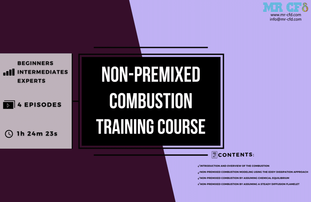
We are excited to have you join us for our Non-Premixed Combustion Training Course, an all-encompassing curriculum that will teach you how to model non-premixed Combustion using ANSYS Fluent. The modeling of non-premixed Combustion is investigated in depth throughout this course. Topics covered include combustion concepts, eddy dissipation, non-adiabatic, chemical equilibrium, and stable diffusion flamelet modeling.
The principles of Combustion, including the several types of Combustion and the equations that control them, will be covered in depth throughout this course. In addition, you will become acquainted with the user interface of ANSYS Fluent and the core processes required to set up a combustion simulation.
To go deeper into non-premixed combustion modeling, you will examine eddy dissipation modeling, non-adiabatic Combustion, chemical equilibrium, and stable diffusion flamelet modeling. You will get the knowledge necessary to model reactions that are not adiabatic and configure simulations to achieve chemical equilibrium. In addition, you will be guided through setting up, solving, and interpreting the findings of a steady diffusion flamelet simulation.
You will finish this course with a comprehensive understanding of non-premixed combustion modeling utilizing ANSYS Fluent. You will have the skills and information essential to flourish in this field. This course is perfect for anyone, regardless of their degree of experience in the field, who is interested in improving their engineering skills and moving their career forward. Enroll immediately and take the first step toward achieving your goal of being an authority on combustion modeling!
Lesson 1
The first part of this presentation will be an overview of the simulation methodologies and models accessible in ANSYS Fluent and an introduction to Combustion. This section is broken down into the subsections that are detailed below:
- A preliminary discussion followed by an analysis of the Combustion
- A brief introduction to the various applications of Combustion
- A survey of the several branches of physics that are relevant to Combustion
- The physics of Combustion o Combustion from premixed fuel and air
o Premixed Combustion
o Non-premixed Combustion
o Partially premixed Combustion
- Summary of different fast and finite rate chemistry models implemented in ANSYS Fluent
Lesson 2
Lesson, 2 of the ANSYS Fluent course provides a synopsis of the many fast and finite-rate chemical models deployed.
In this lesson, you will learn about modeling non-premixed Combustion with the Eddy Dissipation approach by examining Combustion within a combustion chamber. This will help you understand non-premixed combustion modeling. The following subsections make up this section’s organizational structure:
- An outline of the necessary configurations and settings, including the following:
o Mixture material selection
o Implementation of the Chemkin mechanism
o Volumetric combustion
o The Interaction Between Chemistry And Turbulence
o Coal calculator
o The surface of the wall, the surface of the particle, and the electrochemical
o Apps that answer chemistry problems
o Diffusion at the inlet, Diffusion caused by heat,…
o Choose the species at the boundary, reported residuals
o A database devoted to thermodynamics
- Obtaining graphical outlines by extraction
- The process of data analysis
Lesson 3
In this session, we will discuss Combustion that does not involve premixing. We assume chemical equilibrium among the chemical reactants and products to characterize the combustion process inside a combustion chamber with discrete entrance borders for fuel and air. The following subsections make up this section’s organizational structure:
- Chemical equilibrium state related
- Non-adiabatic or adiabatic: which is it?
- Fuel stream-rich flammability limit
- Developing a table in PDF format for Combustion
- The process of data analysis
Lesson 4
In this lesson, we will discuss Combustion that does not involve the premixing of the fuel and air. Assuming a steady diffusion flamelet submodel, in which the turbulent flame is assumed to be formed of several laminar flame brushes, we model the combustion process inside a combustion chamber with separate inlet borders for fuel and air. This section is further divided into the following subsections:
- Steady-state diffusion flamelet model
- Using a checking mechanism, a flamelet is created.
- Developing a table in PDF format for Combustion
- The process of data analysis
Partially Premixed Combustion
Advanced Combustion Training Course
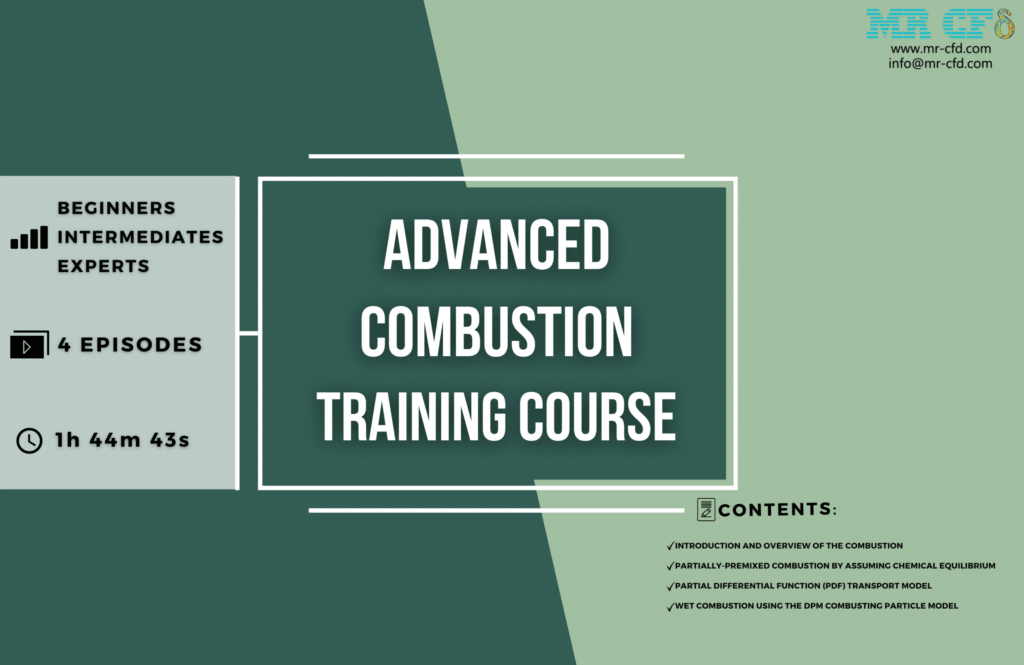
We want to take this opportunity to welcome you to our Advanced Combustion Training Course, which is a complete package designed to teach you everything you need to know about advanced combustion modeling using ANSYS Fluent. Combustion concepts, including partly premixed Combustion, non-adiabatic burning, chemical equilibrium, composition PDF transfer, and wet Combustion using DPM combusting particles, are covered in this course.
You will learn the fundamental concepts of Combustion throughout the course, such as the various types of Combustion and the equations that govern them. You will also gain an understanding of the ANSYS Fluent interface and the primary responsibilities involved in setting up a combustion simulation.
As you progress through the course, you will learn about various combustion processes, including partly premixed Combustion, non-adiabatic Combustion, chemical equilibrium, composition PDF transfer, and wet Combustion using DPM combusting particles. You will be instructed on how to represent non-adiabatic processes as well as how to simulate them. You will also learn how to construct and conduct a simulation of wet Combustion using DPM combusting particles and analyze the simulation outcomes.
After completing this course, you will have a comprehensive understanding of advanced combustion modeling utilizing ANSYS Fluent and the skills and capabilities necessary to thrive in this industry. This class is perfect for anyone interested in expanding their engineering skills and making more headway in their career, regardless of whether they are an amateur or an experienced professional. Sign up now to take the initial step toward becoming an advanced combustion modeling specialist!
Lesson 1
The first part of this presentation will be an overview of the simulation methodologies and models accessible in ANSYS Fluent and an introduction to Combustion. This section is broken down into the subsections that are detailed below:
- A preliminary discussion followed by an analysis of the Combustion
- A brief introduction to the various applications of Combustion
- A survey of the several branches of physics that are relevant to Combustion
- The physics of Combustion o Combustion from premixed fuel and air
o Premixed Combustion
o Non-premixed Combustion
o Partially premixed Combustion
- Summary of different fast and finite rate chemistry models implemented in ANSYS Fluent
Lesson 2
Lesson 2 of the ANSYS Fluent course, provides a synopsis of the many fast and finite-rate chemical models deployed.
In this lesson, we will discuss Combustion that is only partially premixed. We assume that chemical equilibrium exists between the various chemical reactants and products to represent the combustion process inside a combustion chamber with integrated input boundaries for fuel and air. This section is further divided into the following subsections:
- Chemical equilibrium model
- Combustion that is not adiabatic
- Developing a table in PDF format for Combustion
- Using Simmons flame speed model
- The process of data analysis
Lesson 3
The final session will discuss the partial differential function (PDF) transport model combustion composition. To begin, we will apply what we discovered in the previous chapter to modeling the combustion process inside the chamber to generate an initial solution for the PDF transport model.
In the next section, we will demonstrate how to reduce the time required for the computation by considering a few presumptions. Ultimately, we will disregard the assumed assumption and extensively use the PDF transport model to arrive at a definitive and accurate solution. This section is further divided into the following subsections:
- As an initial solution, the partially premixed-equilibrium model will be used.
- agglomeration of the ISAT table for chemistry
- Pure composition PDF transport model
- The process of data analysis
Lesson 4
In this session, we will discuss the DPM Combusting Particle model as it applies to wet Combustion. This method involves the use of combusting particles to build a simulation of a combustion chamber to recreate the process of burning anthracite volatile. Our objective is to track fuel particles as they undergo devolatilization or oxidation, resulting in the release of gases such as carbon dioxide and water vapor. This section is further divided into the following subsections:
- Model for the Transportation of Species Volumetric Combustion
- particle created by the Combustion of DPM
- Wet particles
Combustion Engineering MR CFD Projects
EHD & MHD
Combustion in the Presence of EHD
The ANSYS Fluent simulation presented here focuses on Combustion, while EHD is also present. A straightforward chamber for burning fuel is the focus of this research. Axially flowing airflow and fuel both enter the combustion chamber that is cylindrical in shape.
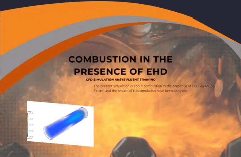
When EHD is applied to the fluid, the fluid develops a charge due to the treatment. We investigate the motion of ionized particles or molecules and their interaction with the electric field and the fluid in the surrounding environment. Following the completion of the calculation, two-dimensional and three-dimensional contours that correspond to temperature, velocity, pressure, and the mass fraction of species (CO2, C10H22, O2, and N2) are obtained. These data are displayed in two ways (without EHD and with EHD) so that the effect of the electric field can be investigated by comparing the two sets of results.
The contours demonstrate that when EHD is applied to the combustion chamber, more heat is applied to the species, which results in higher product temperatures. This is because more heat is applied to the species when EHD is applied. The rate of the combustion reaction is increased when the temperature of the reactive species that is being studied is raised. Additionally, by analyzing the behavior of reaction products, one can determine whether or not the combustion reaction that takes place in the presence of EHD will result in a reaction of a higher quality.
Fluidized Bed Reactors
Circulating Fluidized Bed (CFB) Gasifier
Because of its inherent benefits, such as a high circulation rate, low operating temperature, broad fuel flexibility, and negligible pollutant emissions, the circulation Fluidized Bed gasifier is widely used in both industrial applications and academic research. The findings of this simulation, which involved simulating a straightforward CFB cycle, are presented here.
A vertical inlet is used for the oxidizer, and a horizontal inlet is used for the fuel; after the air and fuel have been mixed, they begin flameless Combustion in a vertical section and then enter the cyclone to separate unburned ashes as polluted air; the unburned fuel then circulates to the bottom of the downstream section and enters the process again; and heavy sands and ashes exit from the bottom outlet. To replicate the behavior of solids, this simulation used the particle density function, also known as the PDF.
The simulation findings indicate that the ignition of the fuel-air mixture occurs in the vertical chamber, and the hot gases from the ignition are cooled in the cyclone and the second chamber. Additionally, the polluting gases produced by the entire face are investigated. The cyclone segregates items that have not been burned, which are fed back into the combustion process.
Fluidized Bed Reactor with Reaction
The ANSYS Fluent software is used to model a fluidized bed polymerization reactor for this simulation. This CFD project is carried out, and a CFD investigation is carried out. The transformation of raw materials into finished goods is the primary function of a reactor, which is a piece of equipment that catalyzes various chemical reactions (such as conversion, composition, and decomposition, amongst others).
The fluidized bed-type reactor offers several benefits, including a high heat transfer rate and a high mass transfer rate, a smaller heat transfer surface, homogeneous temperature distribution, appropriate temperature management, and complete and rapid mixing of reactors and catalysts.
We have validated the results of a fluidized bed reactor with a numerical inquiry based on our last Project. Based on that study, we have explored complete reactions inside our reactor, and the results have been compared to a model without reactions.
The gas flow enters the reactor vertically and upward at a speed of 0.3 meters per second, yet the reactor does not receive any solid particles. The current study explores the behavior of suspended solid particles in the gas flow over time and the pressure drop caused by the reactor’s intake to its exhaust.
Following the simulation, two-dimensional contours relating to the mixture pressure, gas flow velocity and suspended solids, and volume fraction of the gas flow and solid suspended particles are acquired from zero to one second in duration. These contours cover the time range from zero to one second.
Because of our earlier simulation, our attention is now on the reactions; the temperature rise that is caused by the reactions is apparent, and by monitoring the species that are formed as a result of the reactions, you can see the cycle of the reactions and species that are present in the domain in the limited amount of time. Because of our earlier simulation, the temperature rise caused by the reactions is evident.
Biomass
The current issue utilizes the ANSYS Fluent software to do a simulation of the process of biomass combustion inside a gasifier chamber. This CFD project is carried out, and a CFD investigation is carried out. Biomass is the material that is utilized for Combustion; this material reacts with the oxidizer during the process. It is a biomass substance that is generated from wheat straw that combines with oxygen to produce synthetic gas as a healthy fuel, and a variety of gas species are engaged in this reaction, either as reactants or as products.
Two distinct inlets in the upper region provide the chamber access to biomass and air fuel. In the lowest portion of the chamber, it generates a mass of materials, some of which are ash and coal that are only partially combustible. When everything is said and done, the gas produced is expelled through the outlet at the bottom of the chamber and into the subsequent stage, which is the boiler responsible for starting the combustion process.
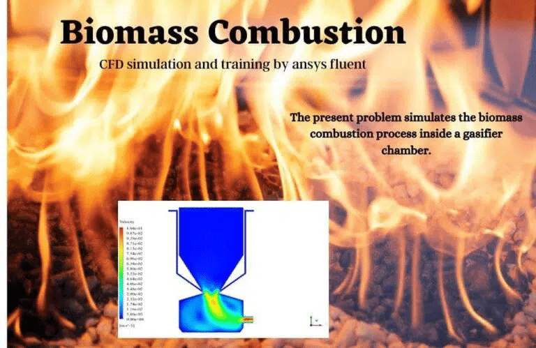
To define the non-premixed Combustion, we import a file that contains a probability density function (PDF). It is a mixture that consists of biomass, air, and other gaseous species, and according to the Fluent program, the rich flammability limit of the fuel flow for this mixture is equivalent to 0.1.
Additionally, the fuel must be introduced into the chamber as individual particles. This indicates that the Lagrangian approach is being used to define the process of injecting this material into the chamber. As a result, we employ the Discrete Phase Model, also known as the DPM.
In addition, we define what is known as the Radiation model since the combustion process results in the emission of radiant heat energy from the flames. The P1 model is the one that we make use of in this particular model. This is the explanation because the process involves Combustion, and the thickness of its optical layer is relatively large.
In summary, we can generate contours in two dimensions related to pressure, temperature, velocity, and density. In addition, we calculate the radiation temperature, the mass fraction of water and vapor, and the mass fraction of species. The findings demonstrate that Combustion is initiated and carried out in response to the introduction of fuel particles, as hypothesized, and that the temperature of the combustion chamber rises as a result.
The buildup of particles on the relatively tiny intake surface in the inlet area is the primary cause of the velocity reaching its maximum value. At the point where the nozzle opened, the temperature was the maximum. The findings also demonstrate the buildup of soot in the output area of the Design.
Radiation
Rosseland Radiation Model, Combustion of Train in Tunnel
In this Project, we use the ANSYS Fluent software to do a numerical simulation of the combustion process on the train while it is within the tunnel. We consider Rosseland radiation. This Project’s objective is to research the radiation heat transfer brought about by the combustion process that occurs on the train while it is within the tunnel. A significant amount of heat is produced whenever there is a combustion reaction. This high heat could potentially cause radiation to be released into the environment around it.
After deciding, the contours corresponding to temperature, velocity, radiative heat flux, and the mass fraction of fuel, carbon dioxide, oxygen, and water vapor have been obtained. The findings indicate that the combustion reaction that was supposed to occur on the train’s outer body occurred. The train’s body develops fuel leaks, which react with the surrounding air’s oxygen. This chemical reaction during combustion results in the generation of carbon dioxide as well as a sizeable amount of thermal energy.
A significant increase train body’s temperature body and the radiative heat flow may be seen in the locomotive section where Combustion has taken place. The Radiation Model Training Course has reached its third episode after completing this CFD Project.
Radiation Heat Transfer in Combustion Chamber
The ANSYS Fluent software is being utilized to examine the stable burning of methane and air within an essential extended cubical combustion chamber for this research. This CFD project is carried out, and a CFD investigation is carried out. Because combustion chambers reach very high temperatures, it is necessary to consider the heat transfer that occurs via radiation.
Within the chamber, the static temperature of the combination reaches a maximum value of 3500 k during this Project. Inlets allow for the introduction of methane and air into the domain; however, only one of the inlets is used to introduce methane.
In addition, because of the high temperature inside the combustion chamber, the heat transfer that occurs as a result of radiation needs to be considered as well. Because of this, the Discrete Ordinates (DO) model has also been enabled.
When finding a solution has been completed, the inside of the combustion chamber will have two-dimensional contours associated with the temperature, velocity, species mass fraction, streamlines, and velocity vectors, among other variables. At the output, the mass flow rate of the combination has been calculated to be 0.004885042 kg/s.
The combustion chamber is the primary location for most of the combustion processes. This is made abundantly clear by the contour of temperature reaction heat, which demonstrates that the most significant temperature gradient and maximum reaction heat are shown. Additionally, the presence of the combustion process is evident from the contours of the species mass fractions. For example, the CO2 mass fraction contour illustrates how suddenly the CO2 mass fraction rises due to Combustion.
Wet Combustion with DPM
Wet Combustion Using DPM Combusting Particle
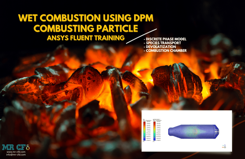
It is important to note that the injection process takes 0.5 seconds and that the liquid component of the fuel makes up 2% of the total. During this time, hot air is being sucked into the combustion chamber. This raises the temperature of the particles, which ultimately results in the release of the volatile portion.
Simulations of anthracite particle simulations have been created using species transport and a discrete phase model (DPM). The type of combusting particles that are used has a liquid fraction that is 2%. Particles having a nonspherical form and a rosin-rammler diameter distribution have an initial temperature of 325K.
As soon as the injection process begins in the combustion chamber, the moisture in the anthracite will begin to evaporate. Even though there is enough oxygen supply in the region, the reaction won’t occur until the volatile fraction has been liberated. The volatile component oxidizes, which results in the production of carbon dioxide and steam. The energy released during the reaction causes the temperature in the chamber to rise to about 2400K.
Explosion
Jet Fan Application in a Tunnel Considering a Car Explosion
The ANSYS Fluent simulation is about an automobile explosion in a tunnel. This research hypothesizes that an automobile will catch fire due to a gasoline leak and subsequent interaction with the airflow. This vehicle is making its way through the tunnel’s interior right now. As a result of the explosion, a fire was started, and the tunnel became filled with carbon dioxide. Because the tunnel is sealed off, the space is filled with carbon dioxide, which cannot escape into the open air.
This behavior poses a risk to other vehicles on the road and pedestrians. Because of this, they install machinery known as jet fans on the tunnel’s roof. These jet fans are equipped with fans that draw carbon dioxide and other pollutants up to the tunnel’s roof. These gases are drawn into the jet fans, which are then thrust forward and expelled. Therefore, the fundamental function of these jet fans is to stop an excessive amount of the release of toxic gases.
To proceed with the modeling, it has been assumed that the combustion reaction has already occurred. Because of this, defining the combustion reaction is unnecessary; instead, one needs to represent the release of carbon dioxide from Combustion.
Following the completion of the calculation, two-dimensional and three-dimensional contours that relate to the pressure, velocity, temperature, and mass fraction of CO2 are obtained. The findings demonstrate no issues with the functioning of the jet fan system. The explosion occurs in the vehicle’s trunk, releasing substantial heat and carbon dioxide.
This CO2 gas will travel upwards because of the existence of these jet fans, and then it will be sucked into the jet fans. Because of this, the system stops the CO2 and other pollutants from spreading throughout the tunnel’s interior. This modeling was carried out once more without using jet fans so that the results could be compared more accurately and the quality of the performance of the jet fans could be assessed.
The only variation from the earlier model is that the fan boundary condition is not employed in the part of the jet fan that is initially being simulated. All of the other simulation conditions are the same. The findings indicate that a buildup of carbon dioxide gas occurs inside the tunnel when the jet fan is not operating.
Hypersonic Combustion (Viscous Heating)
Hypersonic Combustion in Scramjet with Viscous Heating
Hypersonic Combustion in Scramjet with Viscous Heating has been simulated during this research. The results of the simulation have been analyzed with the help of the program known as ANSYS Fluent. This CFD project is carried out, and a CFD investigation is carried out.
Scramjets are a subcategory of ramjets capable of traveling at hypersonic speeds despite their engines not containing any motion device. The ramjet was the precursor to the technology later known as scramjet. It’s possible that the ramjets won’t even reach supersonic speed, but scramjets can travel at hypersonic speeds. A Mach number of more than one denotes supersonic speed, whereas a Mach number of more than five indicates hypersonic speed.
The simulation of hypersonic Combustion within a scramjet engine is the focus of this Project. The temperature of the entire domain is equal to 300 kelvin, and the Mach number of the incoming air has been set at 6. In the portion of the nozzle that is in the middle, the Mach number approaches 1. This is the point at which hydrogen is injected into the flow at a Mach number higher than 1. As a result, the Combustion will take place within the nozzle.
When finding a solution is complete, the results include obtaining two-dimensional contours and vectors of flow pressure, temperature, velocity, Mach number, density, and turbulence intensity. At first, airflow will enter the domain from the intake face and proceed to the combustion part while slowing down to Mach number 1. After then, it moves forward at a quicker pace towards the exit. The amount temperature is more than 4000 K due to the Combustion. Additionally, the effect of viscous heating can be seen in the elements closest to the wall.
Combustion Industrial Companies
There are a large number of businesses that fall under the category of combustion engineering. These businesses offer a variety of products and services that are connected to combustion systems. Some examples of these products and services include burners, boilers, and pollution control technologies. The following are some examples of companies involved in the combustion industry:
– Babcock & Wilcox: Babcock & Wilcox is a global leader in energy and environmental technology, providing products and services related to the Design, build, and operation of power generating systems, including boilers and pollution control systems. Babcock & Wilcox provides goods and services relevant to the Design, construction, and operation of power generation systems.
– John Zink Hamworthy Combustion: John Zink Hamworthy Combustion is a leading provider of combustion equipment and technology, including burners, flares, and thermal oxidizers. They serve a wide variety of industries, including the oil and gas industry, the petrochemical industry, and the power generating industry.
– Honeywell UOP: Honeywell UOP is a leading provider of process technologies, such as catalysts and adsorbents, used to manufacture fuels, chemicals, and other goods. These technologies are employed in a variety of industries. They provide various combustion-related technologies, such as catalytic Combustion, low NOx burners, and emissions control systems.
– Alfa Laval: Alfa Laval is a global equipment provider and solutions for heat transfer, separation, and fluid handling. They serve various industries, including energy, food and beverage, and pharmaceutical. Burners, heat exchangers, and systems for controlling air pollution are some of the combustion-related items that may be purchased from this company.
– Siemens Energy: Siemens Energy is a global provider of energy technologies, including power generation systems, turbines, and control systems. Siemens Energy was founded in 1847 and is headquartered in Munich, Germany. They provide a vast assortment of goods and services linked to Combustion, such as burners, boilers, and emissions control systems, amongst other things.

MR CFD Industrial Experience in the Combustion Field
Following are some examples of a Combustion industrial project recently simulated and analyzed by MR CFD in cooperation with related companies.
Ramjet Engine, Design, and Combustion Optimization (SR-71 Blackbird)
By propelling the engine forward, rather than using a rotating compressor, an air-breathing jet engine known as a ramjet can compress the air drawn into the engine. Because a ramjet cannot function while the airspeed is at a complete standstill, it cannot be used to propel an aircraft during the entirety of the flight. To reach a speed at which the ramjet may begin to deliver thrust, the aircraft equipped with ramjets requires extra propulsion.
Combustion that results in thrust generation in a ramjet occurs slower than the combustor’s sound speed. The air sucked into the engine at the inlet must be slowed down for a vehicle to travel at supersonic speeds. As a result of the shock waves in the inlet, the propulsion system’s performance diminishes. Over a speed of Mach 5, ramjet propulsion is only moderately effective.
In this predicament, fuel is an absolute necessity. When other favorable aspects are considered, such as that at high Mach numbers, the air’s average temperature is higher; hydrogen is beneficial because of its well-known and relatively short inflammatory delay.
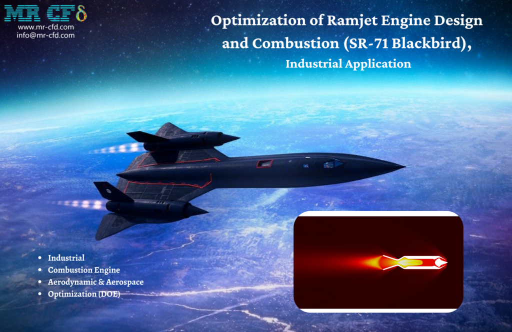
Within the context of this simulation, an SR-71 Black Bird traveling at 3.3 Mach is considered. The modeling effort aims to explore the ramjet engine’s parameters to understand better what occurs there. Following this phase, three of the most critical parameters are chosen, and the solution is then optimized in the ANSYS Workbench software by employing the DOE method.
As was just indicated, the first thing that needs to be done is to imitate the engine of the SR-71 Black Bird, which is a ramjet engine and does not contain any moving parts on the interior. The speed of the jet corresponds to a Mach number of 3.3. A gap of seventy centimeters separates the chamber intake and the injection slot inside the chamber. The engine receives an injection of the fuel, which is hydrogen, at a mass flow rate ratio of 1 to 50 about the air. It is important to note that the injection angle is 0 degrees, indicating that the fuel is injected perpendicular to the airflow.
The Design of the Experiment study is performed on the solution so that the device performance may be optimized and the most fuel can be utilized. Thus the highest possible thrust number can be obtained. We have picked three parameters that significantly impact the overall findings to investigate the impacts of varying them. The following constitutes each of the parameters:
- Rate of Mass Transfer of Fuel
- The angle of injection
- The distance from the engine inlet to the injection slot on the fuel injector
- 138 kg/s – 0.21 kg/s
- (-45) degrees and 45 degrees (positive in the direction of the airflow and negative in the opposite direction) degrees
- 50 cm – 70 cm
At long last, 3D graphs of the parameters and the effects those factors have on the thrust of the ramjet have been accomplished. Additionally, the DOE model provided us with the minimum and maximum values of the parameters while also considering their interactions. The following configurations would yield the most significant and lowest amounts of thrust in the simulation that was carried out, respectively:
The maximum possible value for Thrust:
- 1784 kilograms per second (kilograms per second) fuel mass flow rate
- 70 centimeters in terms of the injection angle
- The angle that is equal to the distance between the injection slot and the inlet of the engine plus 0.6568 degrees
The number with the fewest thrusts:
- 138 kilograms per second in terms of fuel mass flow rate.
- The injection angle is calculated as the distance of the injection slot from the engine inlet plus 45 degrees. It is equal to 65.994 centimeters.
- The angle that is made by adding 45 degrees to the distance between the injection slot and the engine inlet
The simulation of an industrial furnace has been carried out as part of this Project. The simulation results have been analyzed with the help of the ANSYS Fluent program. This CFD project is carried out, and a CFD investigation is carried out.
In this endeavor, the Ansys Fluent software was used to perform a numerical simulation of an industrial furnace. Methane fuel is burned in the furnace being replicated for this Project. This aims to heat the methane within the pipes so that it may be transferred more quickly and with less effort.
When the findings are examined, it is clear that there has been a rise in temperature at the pipe’s output in comparison to the temperature at the pipe’s entrance. Combustion occurs once the fuel is introduced into the furnace, where it is combined with the air already present. The floor of the furnace contains six burners that have been installed there.
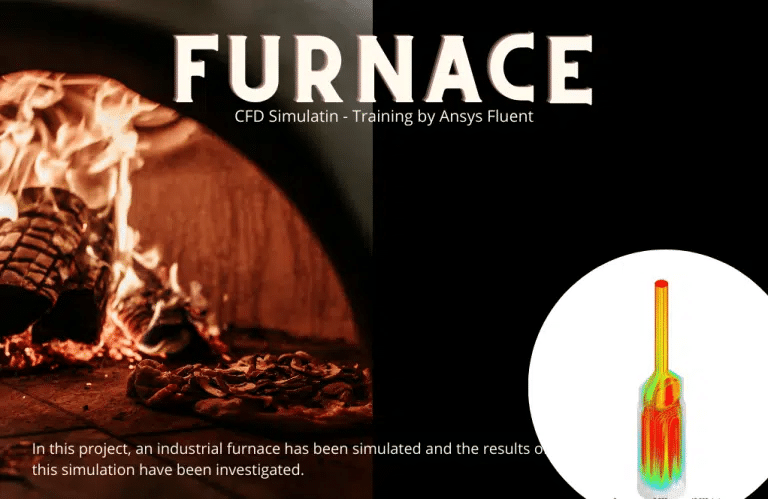
When working with heavy mineral flood oil, it is frequently required to heat the oil in the furnace to reduce its viscosity and make moving the oil more manageable. The temperature of methane will be brought up to a higher level as a result of this effort.
In this endeavor, the ANSYS Fluent software was used to perform a numerical simulation of an industrial furnace. Methane fuel is burned in the furnace being replicated for this Project. This aims to heat the methane within the pipes so that it may be transferred more quickly and with less effort. When the findings are examined, it is clear that there has been a rise in temperature at the pipe’s output in comparison to the temperature at the pipe’s entrance.
One of the priceless presents that mother nature has bestowed on us is oil. Denying oil’s influence on humankind’s economic, political, and social conditions is impossible. Oil, a crucial component, has contributed to the economy’s growth, as well as jobs and tranquility.
As a result, one of the most significant issues the oil industry faces is the movement of oil or oil products through transmission lines. This is a concern since oil has a high viscosity, making it difficult to travel through the pipeline. Because of this, heating the desired fluid reduces its viscosity, which improves the fluid’s movement within the tube.
Like other pieces of machinery, furnaces have progressed over time, and as our understanding of engineering has grown, so have how it is possible to improve both their effectiveness and their level of safety while using them. In the process of developing and producing various kinds of furnaces, one of the intellectual preoccupations of the engineers is to maximize the efficiency of the equipment as much as possible, as well as to improve safety, simplify the process as much as possible, provide direction, and to allow for the use of a variety of fuels.
Combustion occurs once the fuel is introduced into the furnace, where it is combined with the air already present. The floor of the furnace contains six burners that have been installed there. When the flame enters the radiating area of the furnace, it strikes the pipes and causes the liquid contained within the pipe, methane, to heat up. Burnt gases come out of the chimney when combustion gases are expelled.
You may find the Learning Products in the Combustion CFD simulation category in Training Shop. You can also benefit from Combustion Training Packages appropriate for Beginner, Intermediate, and Advanced users of ANSYS Fluent. Also, MR CFD is presenting the most comprehensive Combustion Training Course for all ANSYS Fluent users from Beginner to Experts.
Our services are not limited to the mentioned subjects. The MR CFD is ready to undertake different and challenging projects in the Combustion modeling field ordered by our customers. We even carry out CFD simulations for any abstract or concept Design you have to turn them into reality and even help you reach the best strategy for what you may have imagined. You can benefit from MR CFD expert Consultation for free and then Outsource your Industrial and Academic CFD project to be simulated and trained.
By outsourcing your Project to MR CFD as a CFD simulation consultant, you will not only receive the related Project’s resource files (Geometry, Mesh, Case & Data, …), but also you will be provided with an extensive tutorial video demonstrating how you can create the geometry, mesh, and define the needed settings (pre-processing, processing, and post-processing) in the ANSYS Fluent software. Additionally, post-technical support is available to clarify issues and ambiguities.


