CFD Project Outsourcing
Outsource your CFD project to the MR CFD simulation engineering team. Our experts are ready to carry out every CFD project in all related engineering fields. Our services include industrial and academic purposes, considering the ANSYS Fluent software's wide range of CFD simulations. By outsourcing your project, you can benefit from MR CFD's primary services, including CFD Consultant, CFD Training, and CFD Simulation.
The project freelancing procedure is as follows:
An official contract will be set based on your project description and details.
As we start your project, you will have access to our Portal to track its progress.
You will receive the project's resource files after you confirm the final report.
Finally, you will receive a comprehensive training video and technical support.
What is Moving Mesh (Sliding Mesh)?
When a time-accurate solution for rotor-stator interaction (rather than a time-averaged solution) is desired, you must use the sliding mesh model to compute the unsteady flow field. The sliding mesh model is the most accurate method for simulating flows in multiple moving reference frames and is the most computationally demanding. As was mentioned, the sliding mesh model is theoretically the most accurate method for simulating rotating flows, and it can correctly describe the whole transient startup. However, it is also the most computationally demanding. This technique, applied to the specific case, creates two separate cell zones. Each cell zone is bounded by an interface that meets the opposing one. The two cell zones will slide relative to one another along the mesh interface in discrete steps. The AMI (arbitrary mesh interface) operates by projecting one patch’s geometry onto the other. In other words, the two sub-domains are geometrically separated but numerically connected by the AMI, ensuring that the values of a generic field are the same on both sides of the interface. The external cell is a simple steady partition in which the mesh does not move during the calculations. Instead, the internal partition, the cylindrical one, is a cell zone that rotates during the simulations. After each step, the internal mesh is rotated at a prescribed angle. The advantage of this technique is that it ensures the best accuracy avoiding, at the same time, mesh deformation.
ANSYS Fluent has various modules for modeling and simulating moving objects (moving reference frame, moving mesh, dynamic mesh, moving wall). Each module has its limitation, advantage, and disadvantage, and in most problems, only one and a particular module can correctly model the system of interest. For example, we can model HAWTs by both MRF and moving mesh modules, and the result of both modules would be the same. However, due to the high computational time of the moving-mesh module, it’s more economical to use the MRF module, and we prefer to model HAWT by the MRF method. But for VAWT, it is impossible to model it with the MRF model because the wind turbine blade situation VS wind direction will change over time. Therefore, VAWTs must be simulated using a moving mesh module.
Moving Mesh (Sliding Mesh) is a computational modeling approach in fluid dynamics simulations. The computational mesh moves to simulate fluid or solid objects in a domain. Many fluid flow problems have changing domain shapes or boundaries. Rotating turbine blades or fluid interface distortion may cause this. Moving meshes capture these dynamic changes.
The Moving Mesh approach deforms the computational mesh to match changing geometry. The simulation accurately tracks the fluid-solid interface or moving boundaries. Each time step, mesh nodes are moved to accommodate object form and location changes. The sliding mesh method simulates fluid-structure interaction problems such as flow around spinning machines, oscillating structures, and fluid-elastic vibrations. It dynamically updates the mesh to adapt changing geometry to simulate complex fluid flow phenomena. Engineers and researchers can study fluid flow and moving objects using a moving mesh technique and using this method for aerospace, automotive, energy, and biomechanics, where fluid-structure interaction modeling is critical.
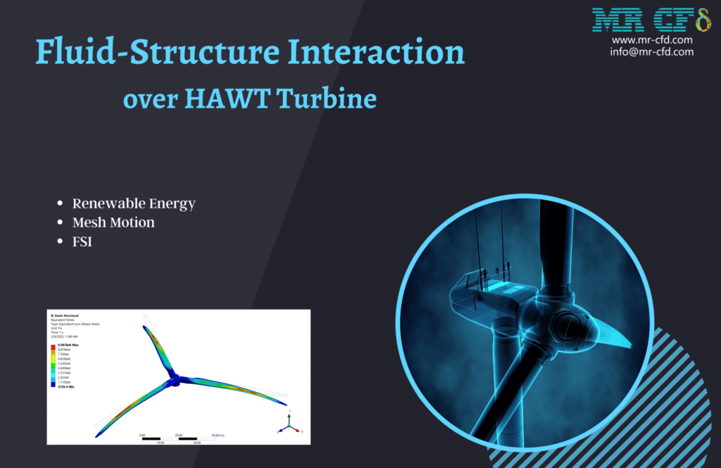
Fluid-Structure Interaction over HAWT Turbine Vibration
This study analyzes fluid-structure interaction over a HAWT turbine. This simulation warms the turbine with a 25 m/s flow at 12 RPM. The one-way FSI technique investigated fluid effects on the structure. The blade tips deformed 0.2 m. Bending stress and strain were also examined. Mesh Motion and FSI replicate HAWT turbine motion: 25 m/s and 101235 pa. RPM was 12, and the hub was basic. Fluent simulates fluid while ANSYS Structure models structure. We calculated turbine deformation, strain, and stress using domain and structural section pressure and speed.
How can Moving Mesh (Mesh Motion) CFD simulation be applied in Engineering and Industries?
Moving Mesh CFD simulation is used in engineering and industry. Examples of this method:
 Aerospace and Aeronautics:
– Simulating takeoff and landing flow around propellers, helicopter rotors, or airplane wings.
– Assessing flap and slat aerodynamics.
– Studying jet engine airflow-moving component interactions.
Auto Industry:
– Car, truck, and motorbike aerodynamics research.
– Improving radiator fans and air ducts.
– Simulating tire/wheel flow.
Energy Production:
– Analyzing fluid flow in turbines, compressors, and pumps.
– Testing heat exchangers and cooling systems.
– Simulating wind turbines and airflow.
Darrieus wind turbine: Proposal for a new performance prediction model based on CFD
Vertical-axis wind turbines (VAWTs) have main rotor shafts that are transverse to the wind and perpendicular to the ground. VAWTs capture wind energy in all azimuth angles using this setup. Three varieties of VAWTs are drag-based Savonius, lift-generating Darrieus, and H-type.
H-type wind turbines are Darrieus with various blades. This Project validates a linked work, “The Darrieus wind turbine: Proposal for a new performance prediction model based on CFD.” The paper 2D simulation shows three NACA0021 blades and a 1010mm diameter turbine.
Air incompressibility necessitates a pressure-based solver. The simulation is transient. Most notably, the sliding mesh rotates the rotor to test wind turbine performance. Wind turbines take several rotations to stabilize, usually in the fifth or sixth round. We must check the wind turbine’s moment coefficient. As the difference between the two rounds drops below 2%, convergence is assured.
This paper simulates a power plant inside a pipe using a lift-based in-pipe spherical turbine. NACA airfoils make turbine hydrofoils. ANSYS Fluent simulated and assessed a spherical lift turbine CAD model based on peak and bottom volume discharge rates. Discharge changes determine power outputs.
Saving water and energy has been a global priority for years and is predicted to grow. Many technical methods have been proposed to replace pressure relief valves with power generators to generate electricity and safely regulate water distribution network pressure. Hydraulic energy efficiency, which may be directly transformed into power, increases water supply system energy efficiency. This approach leverages clean energy, generally disregarded in water resources, to reduce power grid dependence and system operating costs.
We will simulate the water turbine within the pipe using mesh motion and compare the results to the article—111 m^3/s of mass flow and 153,626 rpm of spinning. The paper diagram and pipeline centerline pressure diagram are compared. This study found that hydropower usage in water distribution systems depends on fluid flow, effective head, pipe diameter, hydrofoil specifications, and turbine components.
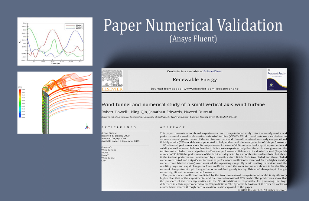
Wind tunnel and numerical study of a small vertical axis wind turbine
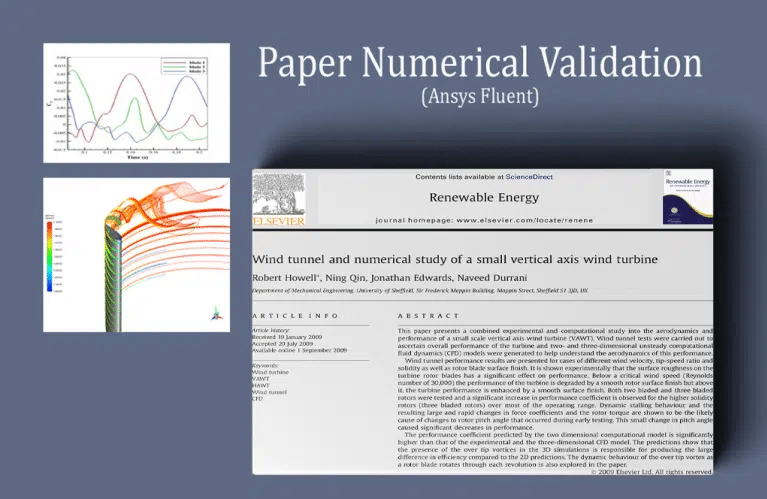
ANSYS Fluent models airflow over a Vertical Axis Wind Turbine (VAWT). We analyze this CFD project. “Wind tunnel and numerical study of a small vertical axis wind turbine” is the reference for the simulation. The article validates its findings. Mesh motion enabled the transient solver.
This Project simulates the Darrius VAWT. The turbine has many curved airfoil blades on a shaft. The vertical primary rotor of this turbine can be mounted near the ground. After this simulation, we checked and validated our results with the papers. Figure 14 depicts torque coefficient variations over time for each rotor blade.
Modern composite materials and design innovations, such as aerodynamic wingtips that cause the spreader wing connections to have a static load since the vertically oriented blades can twist and bend throughout each turn and break apart, can solve these problems. Tip vortexes on VAWT blades also affect spinning. Blade phase angle affects tip vortex strength. The tip vortex power indicates blade lift force.
Blade lift force increases with tip vortex core strength. Lift changes as the turbine rotor blade spins through phase angles, causing this strength to shift. Note that the maximum lift and tip vortex strength may occur somewhat apart. The flow’s response to the rotor blade’s changing lift will cause this.
HAWT and VAWT Comparison (Mesh Motion and MRF)
This tutorial simulates fluid flow through vertical-axis wind turbines (VAWTs) and horizontal-axis wind turbines (HAWTs). These wind turbines rotate differently in global coordinate systems and require distinct modeling methods. Engineers love CFD’s turbomachine fluid flow modeling. Turbomachines convert fluid flow kinetic energy to turbine or pump rotation.
Turbomachinery Training Course episode 5. As said, the VAWT revolves around an axis perpendicular to the flow direction, while the HAWT are turbomachines revolving around a parallel axis. Thus, mesh motion and linking the rotating and stationary zones with an interface boundary are the best ways to describe VAWT rotation. For mesh rotation, transient simulation is needed.
HAWTs can be modeled using the frame motion technique and applying the necessary rotating speed to the turbine blades without worrying about steady or non-steady time studies. This technique misses time-dependent phenomena. It will also be shown how a user can define lift, drag, and moment reports for turbine blades and acquire results and data on turbomachine motion, which is crucial when constructing such structures. This article will teach you how to simulate turbomachine rotating motion using mesh and frame motion. Mesh motion is needed to model VAWT turbomachines accurately. Frame motion is adequate to simulate spinning structures like HAWT.
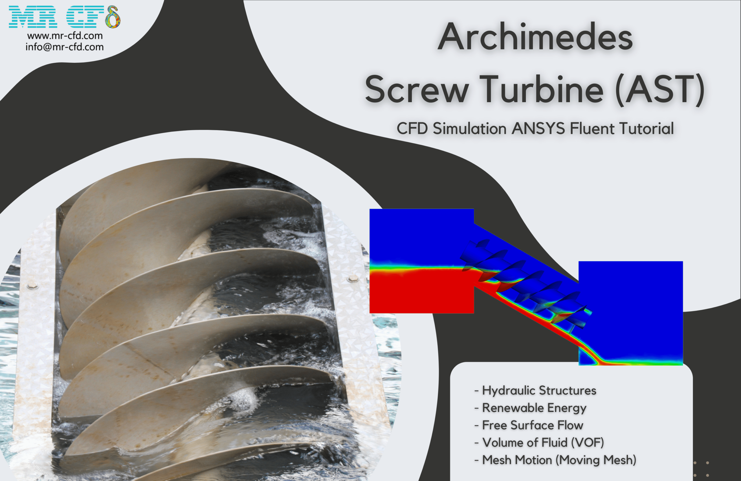
Archimedes Screw Turbine (AST)
This Project simulated a 3-blade Archimedes Screw Turbine (AST). ANSYS Fluent examined simulation results. We analyze this CFD project. Archimedes Screw Generator (AST), or screw turbine, is a hydraulic machine that uses the Archimedean screw to transform upstream flow potential energy into kinetic energy.
The turbine is on a river, and water flows through it. The upper domain box has a fixed flow. Water enters the domain from above while the turbine is at a 30-degree angle. All faces are fixed walls, and the output gauge pressure is 0. The answer yields two- and three-dimensional contours and vectors linked to water pressure and velocity. Water flows into the upper box, over the turbine blades, and out the outlet face. The turbine’s maximum power at 10 rpm is 5 kW. ANSYS Fluent’s Moment parameter multiplied with the turbine’s angular velocity in radians per second, which for this Project is 1.05, gives the output power.
Serrated Airfoil and Plain Airfoil Comparison, Darrieus VAWT
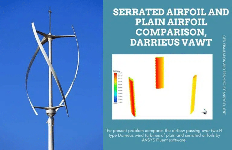
ANSYS Fluent evaluates airflow over two H-type Darrieus wind turbines with plain and serrated airfoils. We analyze this CFD project. The vertical axis wind turbine (VAWT) Darrieus generates power from wind energy. The turbine has many curved airfoil blades on a shaft.
This turbine has a vertical primary rotor. Its most significant benefit is vertical wind turbines’ ability to operate at low elevations without wind direction adjustment. Dynamic stall caused by spinning blade angle of attack variations affects vertical axis wind turbine (VAWT) performance.
When dynamic stall vortices from the blade leading-edge are carried downstream, torque changes are significant and rapid. Turbine blades periodically experience dynamic stalls at Reynolds numbers below 105. Lift coefficient plummets, limiting rotor torque and power production. This Project investigates how sinusoidal serrations on turbine blade leading edges can manage and reduce dynamic flow separation to improve the power performance of a standard H-type VAWT model.
VAWTs face dynamic stalls due to pressure changes. Due to pressure changes, VAWT blades are fatigue-prone. Improved design, particularly leading-edge serrated airfoils, can overcome these limitations. Next, if we look at drag, lift, and power coefficient, serrated airfoils have a little higher drag force than plain ones due to their larger surface area.
The lift coefficient graph shows that serrated airfoils for the vertical axis turbine somewhat enhance lift force. Pressure distribution over two airfoil surfaces may be smoother. Serrated airfoils provide a smoother pressure gradient over two surfaces, increasing lift force. Finally, using serrated airfoils will boost power marginally. Each blade’s rotation cycle increases power, explaining this occurrence. This cycle-by-cycle power increase will smooth and boost power output.
Two-Blade Savonius Wind Turbine
ANSYS Fluent was used to analyze the simulation results of a 3-D Savonius Wind Turbine with two blades. We analyze this CFD project. The vertical axis wind turbine (VAWT) savories generate electricity from wind energy. The turbine has many curved airfoil blades on a shaft.
This turbine has a vertical primary rotor. Its most significant benefit is vertical wind turbines’ ability to operate at low elevations without wind direction adjustment. Two-dimensional pressure, velocity, and streamline contours are obtained after the solution. This product collection shows fluid fluctuations through turbine blades.
They say inner and outer blades have differing pressure and velocity distributions. Flow enters at 10m/s. After the impact with the inner blade, the velocity magnitude falls and reaches zero at a stagnation point, which may create negative torque. The outer blade is pushed clockwise by a high-velocity flow on its rear.
Vertical Axis Wind Turbine (VAWT)
ANSYS Fluent simulates air around a VAWT in this problem. In this scenario, three wind turbine blades rotate at 2.8285 rad/sec while air blows at seven m/s. This simulation demonstrates air flow around wind turbine blades with varied solution parameters. Dynamic stall is significant.
Figures demonstrate air movement around a Virtual Axis Wind Turbine, the issue’s primary focus. Two-dimensional pressure, velocity, and turbulence intensity contours were obtained. Air pressure in front of the blade is crucial for pressure. Velocity contours show blade wakes.
Biomedical Engineering
– Modeling artery and vein blood flow with vascular wall motion.
– Simulating heart valves and blood flow.
– Considering lung and airway mobility, analyzing respiratory fluid dynamics.
Marine/Offshore Engineering:
– Studying ship hydrodynamics, particularly water and propeller/rudder interaction.
– Analyzing wave and current loads on offshore structures like wind turbines and oil platforms.
– Simulating underwater vehicle, submarine, or robot flow.
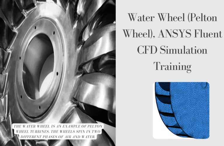
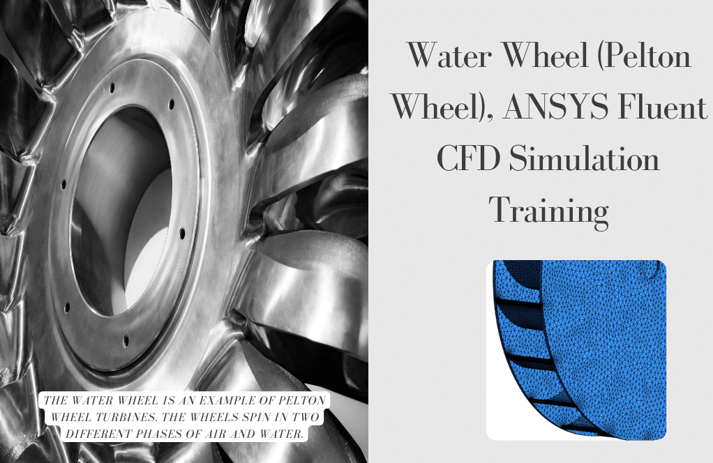
ANSYS Fluent Water Wheel CFD Simulation Training (Pelton Wheel) is the issue. CFD analysis is used to evaluate this CFD project. Waterwheels are Pelton turbines. Water wheels can be positioned horizontally or vertically. ANSYS Fluent solves fluid flow problems using the averaged Navier-Stokes equation.
The water wheel’s free surface border is 0.2 m below the turbine’s 0.7 m diameter. The average river velocity is 3–5 m/s. With no flow drag or bump, determine the turbine’s rotational speed. This CFD simulation has a 60-rpm turbine. Reduced friction force and greater nozzle thrust make the wheels perpendicular to turbine sections. Another turbine section is dry. Thus, the wheels rotate in water and air.
MR CFD services in the Moving Mesh Simulation for Engineering and Industries
MR CFD is a primary CFD (Computational Fluid Dynamics) provider for engineering and industry, featuring Moving Mesh Simulation. They use the Moving Mesh approach to optimize designs, boost performance, and solve complex fluid flow challenges. Services include:
Moving Mesh Simulation Setup:
– MR CFD helps clients define issue geometry, boundary conditions, and mesh motion requirements for Moving Mesh simulations.
– They engage with clients to understand their needs and goals to represent shifting components or limits accurately.
Mesh Generation:
– MR CFD generates high-quality Moving Mesh meshes using innovative mesh-generating algorithms.
– Using cutting-edge software, they build structured or unstructured meshes that flex and adapt to changing geometry.
– Based on flow and object movement, mesh adaption algorithms modify or coarsen the mesh.
Solver Configuration:
– MR CFD chooses efficient Moving Mesh CFD solutions and methods.
– They configure solver settings, time-stepping techniques, and mesh update algorithms for accurate and stable simulations.
– Solver validation and verification assure accurate results.
Postprocessing and visualization:
– MR CFD analyzes and visualizes simulation data.
– They help clients understand fluid flow dynamics with detailed reports, visual representations, and quantitative data analysis.
– Customized visualization tools and methodologies convey results clearly and informatively.
Optimization/Design Improvement:
– MR CFD optimizes designs and improves performance using Moving Mesh simulation results.
– Parametric research, sensitivity analysis, and design optimization determine optimal configurations and operating conditions.
– MR CFD helps companies improve product efficiency, dependability, and safety by developing new solutions.
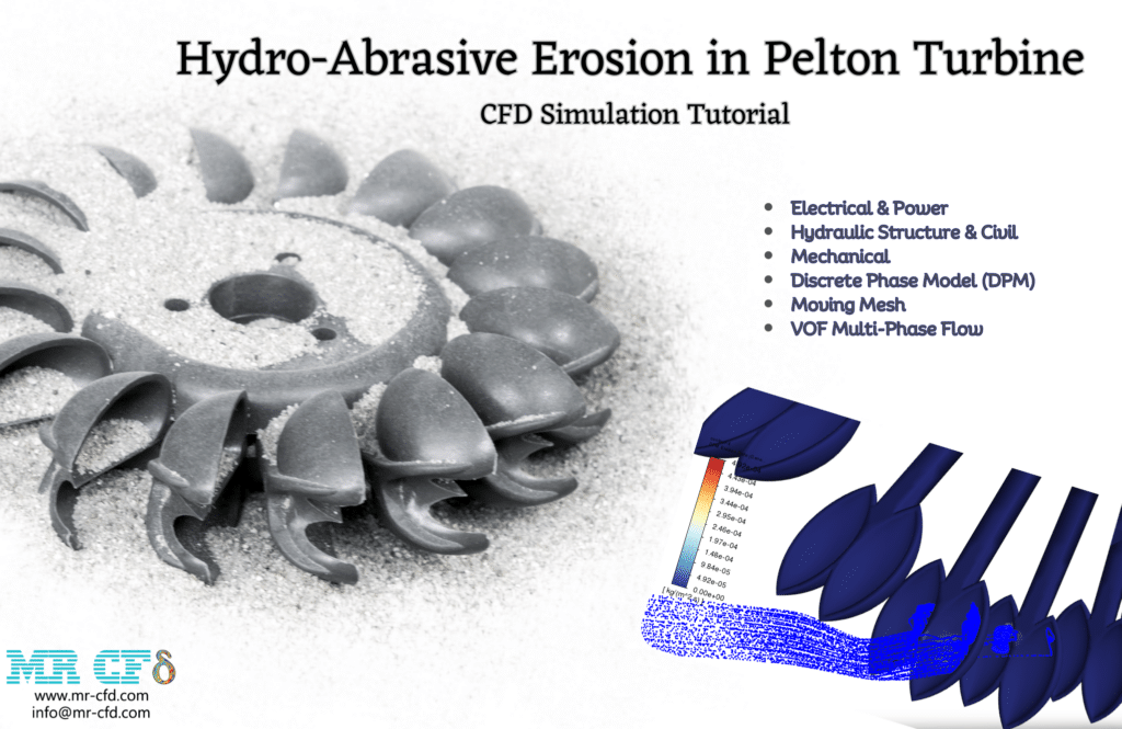
Hydro-Abrasive Erosion in Pelton Turbine
Hydropower systems face Pelton wheel erosion. Hydro turbine Pelton wheels are eroded by high-velocity water jets. Water droplets and sand particles hitting the wheel’s buckets or blades cause this erosion. As water hits the surface, it wears away, diminishing efficiency and damage. Erosion-resistant materials, maintenance, and monitoring reduce erosion. Optimizing water flow and alignment reduces erosion and extends the Pelton wheel lifespan, enabling efficient and sustainable hydropower generation.
After simulation, the high-velocity water jet directly hit the Pelton turbine blades. Cause erosion. Water jet velocity affects hydro-abrasive phenomena—double velocity. The casting material process must account for 12% more erosion. Pelton turbine design life expectancy depends on the high sand particle erosion rate.
Cavitation occurs when the static pressure of a liquid dips below its vapor pressure, creating microscopic gaps filled with vapor. Higher pressures compress these spaces, causing shock waves that can harm gear. Shock waves are intense near the bursting bubble but decrease fast as they move away.
Some engineering fields wear from cavitation. Bursting collapsed cavities near the metal surface creates cyclic stress. This produces metal fatigue and “cavitation” wear. The results demonstrate that cavitation bubbles cover the blades’ suction side and some of the trailing edge. The propeller’s high rotating velocity (1500 rpm) causes super cavitation on its surface.
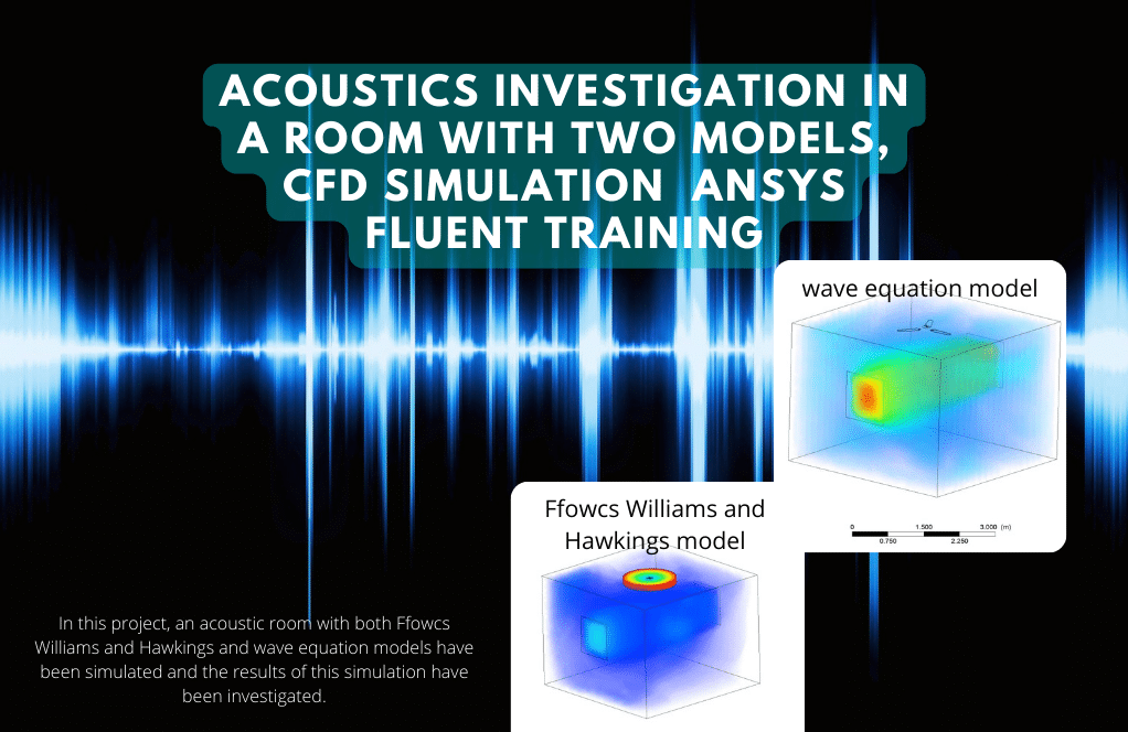
Sound Generation of a Ceiling Fan (FW-H Vs. Wave Equation)
This Project simulates ceiling fan sound generation in a room using Ffowcs Williams and Hawkings and wave equation models. ANSYS Fluent examined simulation results. We analyze this CFD project. Acoustics studies vibration, sound, ultrasound, and infrasound in gases, liquids, and solids. Production, transmission, reception, and sound effects are involved.
After solving, two- and three-dimensional contours and graphs of room pressure, temperature, and velocity are produced. CFD Post depicts room sound pressure and amplitude at Ansys Fluent locations. 3D contours reveal room temperature and velocity, and noise parameters are obtained on fan walls and in the room.
How to Model Moving Mesh inside ANSYS Fluent
Steps to represent moving mesh in ANSYS Fluent:
Geometry Preparation:
– Create or import ANSYS Fluent-compatible geometry for your system or components.
– Clean, fix, and mesh the geometry.
Mesh Generation:
– Generate your geometry’s initial mesh using ANSYS Meshing or other tools.
– Check the mesh quality and resolution for accurate simulations.
– Focus on simulation mesh deformation zones.
Define Mesh Motion:
– Pick “Mesh Motion” from the “Mesh” menu to set mesh motion in ANSYS Fluent.
– Choose the mesh motion type, such as rigid body motion, deformation, or dynamic meshing.
– Set translation, rotation, deformation, and other motion parameters.
Solver setup:
– Set ANSYS Fluent solver settings for moving mesh simulation.
– Based on your problem, choose a segregated or connected solver.
– Set simulation convergence and time step size.
Boundary Conditions:
– Considering the shifting mesh, set simulation boundary conditions.
– Motion-related boundary conditions are prescribed motion, rotational motion, and deformation constraints.
– Ensure that the boundary conditions match the mesh motion and system behavior.
Simulate:
– Start and monitor the ANSYS Fluent simulation.
– Check the mesh motion and simulation progress.
– To ensure stability and convergence, adjust solver settings, time step size, or other parameters.
Postprocessing:
– Using ANSYS Fluent postprocessing tools, examine and understand the simulation findings.
– To understand system behavior, visualize flow patterns, pressure distribution, and other parameters.
– Report, plot, and animate results.
Note that ANSYS Fluent versions differ in steps and choices. Modeling moving mesh simulations in ANSYS Fluent requires thorough instructions and user manuals.
Moving Mesh MR CFD Projects
With several years of experience simulating various problems in various CFD fields using ANSYS Fluent software, the MR CFD team is ready to offer extensive modeling, meshing, and simulation services. Simulation Services for Moving Mesh simulations are categorized as follows:
- Various types of horizontal and vertical axis wind turbine
- Various types and situations of Tidal turbines (two and three and four-bladed)
- Simulation of turbomachinery includes (pumps, compressors, etc.)
- Airplane propeller CFD simulation
- Simulation turbofan and AFT fan
- Simulation of cavitation in Francis, Kaplan, and Pelton turbine
- Simulation of the rescue helicopter
- …
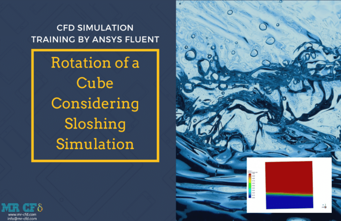
Rotation of a Cube Considering Sloshing
ANSYS Fluent is used to study the rotation of a water-air cube. The cube oscillates around the Y-axis. The cube is 1 m from the rotation axis. Rotational angular velocity changes as 0.252273*sin(2.53*time+36800). This study studies the simplified sloshing effect in fluid containers, which might occur owing to carrier vehicle acceleration. Results reveal that radial distance to the OO line affects cube bottom pressure. Pressure rises away from the OO’s line.
Moving Mesh Application in Industrial Companies
Many industrial companies use moving mesh simulations. Examples of industrial businesses using moving mesh simulations:
Automotive Industry:
– Moving mesh simulations are used by automotive manufacturers to evaluate vehicle aerodynamics during vehicle motion, rotating wheels, and moving components.
– Moving mesh simulations improve vehicle stability, fuel efficiency, drag, and design optimization.
Aerospace industry:
– Aerospace businesses use moving mesh models to investigate fluid flow around wings, flaps, and control surfaces.
– These simulations evaluate aircraft aerodynamics, stability, and control during takeoff, landing, and maneuvers.
Dynamic Stability Derivatives for a Flying Wing (Aircraft)
This Project seeks flying wing aircraft dynamic stability derivatives. Designing a flying wing without a horizontal or vertical tail makes derivatives and stability calculations difficult. ANSYS Fluent software and CFD in flight dynamics can provide us with those derivatives. We created a UDF file to simulate UAV motion. The UAV is flying at Mach 0.6 at sea level. Derivatives are computed from the rate change of Cm and Cl over time.
Energy and Power Generation:
– Moving mesh simulations study fluid flow and heat transfer in gas turbines, wind turbines, and cooling systems for energy and power generation companies.
– By assessing fluid flow, fluid flow, Moving mesh models improve turbine design, energy efficiency, and system performance.
Chemical/Process Industry:
– Chemical and industrial companies use moving mesh simulations to analyze fluid flow and mixing in reactors, tanks, and other equipment.
– These simulations optimize process conditions, product quality, and efficiency.
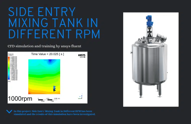
Ansys Fluent Software modeled Side Entry Mixing Tank in Different RPMs in this Project. Ansys Fluent CFD numerical simulation software has simulated a mixing tank. In the oil and gas, water deposition damages storage tanks, causing corrosion, leakage, and source perforation. Mixing is crucial. Due to space constraints, side mixing blades preclude these events. This simulation uses mesh motion at 400, 900, and 1400 rpm.
In this simulation, water settles at the bottom of the mixing tank because it is denser than oil. 1400, 900, and 400 rpm side mixers blended the tank contents. Each item needs the right mixing time. We validated the complete mixing requirement using three sensors in different tank positions and plotted the volume fraction of oil and water for all three points overtime on the chart. These statistics show that 400 rpm mixes in 100 seconds, 900 in 14, and 1400 in 8. Given this pattern, raising the rotating speed to a limited level (900 rpm) reduces mixing time, but increasing it too much has minimal effect. We can ignore it, lowering our engine selection cost.
Petroleum Industry:
– Moving mesh simulations evaluate fluid flow in oil and gas pipelines, offshore structures, and subsea equipment.
– These models evaluate fluid behavior, enhance pipeline designs, and improve offshore installation performance and safety.
Biomedical industry:
– Biomedical firms use moving mesh simulations to examine artery blood flow, respiratory airflow, and medical device fluid-structure interactions.
– Simulations improve patient care, physiological understanding, and medical device design.
MR CFD Industrial Experience in the Moving Mesh Field
Moving mesh simulations help industrial businesses understand the fluid flow, optimize designs, and improve performance. These simulations adequately capture component or boundary motion, helping firms make educated decisions, decrease costs, and improve product and process efficiency and dependability. Some examples of Moving Mesh industrial projects that were recently simulated and analyzed by MR CFD in cooperation with related companies are as follows:
Quadcopter CFD Simulation, Toroidal Propeller vs Simple Propeller, Acoustic Analysis
Toroidal propeller design and installation must address acoustic performance. Propeller shape affects propulsion system noise. Toroidal propellers are quiet and absorb sound waves due to their ring-shaped structure. This enhances passenger and crew comfort. The toroidal propeller is noisy. The propeller’s acoustic performance can be affected by the drone’s speed, external noise sources, and the interaction between the blades and the ring.
Designers may utilize CFD simulations and experimental testing to optimize toroidal propeller acoustics. By researching the propeller’s flow patterns and acoustics, designers can reduce noise and increase efficiency. Toroidal propeller design and application depend on acoustic performance. The propeller has several advantages over older designs, but its acoustic performance must be carefully considered to limit its environmental impact and improve onboard comfort.
This Project simulates a hovering drone with a toroidal and standard propeller to absorb and emit sound—a quadcopter with four 1200 RPM rotors. Quadrotor acoustics affect safety and efficiency. Noise can disrupt pilot-ground crew communication and local fauna. Noisy systems may have imbalanced rotors or aerodynamic difficulties. By optimizing their acoustics, designers can increase quadrotor safety, efficiency, and performance. This can improve quadrotor use in aerial photography and search and rescue.
At 1200 RPM, a standard propeller produced 213 dB. The toroidal propeller reduces this to 85 dB. Turbulence affects propeller sound. As airflow surrounding the propeller gets more turbulent, pressure and velocity changes create noise. In the propeller’s near-field, turbulent flow interacts with the blades and ring structure. Optimizing propeller acoustics requires turbulence consideration.
This article discusses a popular impact turbine. The only impact hydraulic turbine is the Pelton. This turbine generates energy via a fluid jet, per Newton’s second law. This turbine is hit by a pressured water nozzle tangentially to the bucket linked to the runner, rotating the runner.
The buckets are paired to transfer momentum and balance force efficiently. Pellets vary in size. Because these turbines are intended for giant heads, dams employ enormous sizes while distant places utilize tiny sizes to generate electricity. ANSYS Fluent simulates a 300-mm Pelton turbine with 15 buckets in this Project. The turbine’s torque is also the goal of this Project.
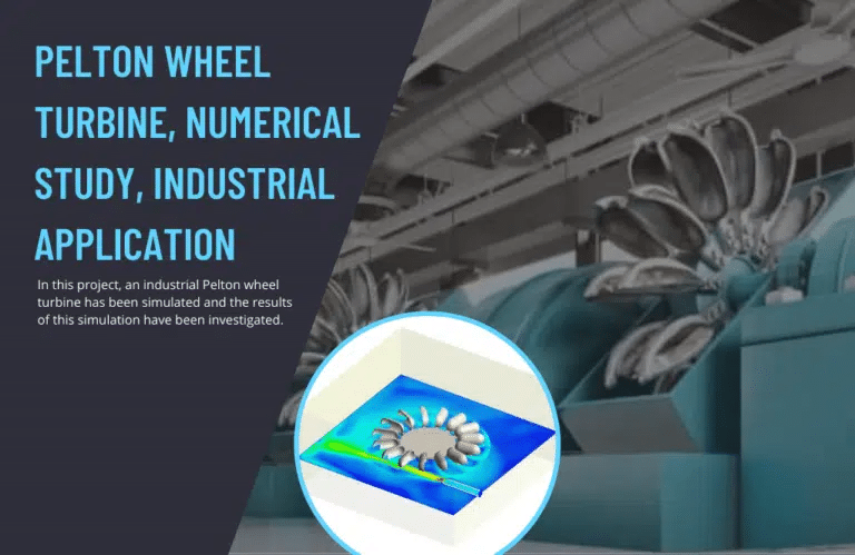
He created his first laboratory turbine from wood in the mid-1870s and installed the first sample of genuine iron in a Nevada mine in 1878. The Pelton wheel’s efficiency and benefits led to mass manufacture. Pelton designed a separator to split the input jet into two equal streams. From 35% to 90%, the same idea improved water cycle efficiency. There are several impact turbines. The most efficient model is Pelton’s.
A disk with multiple blades surrounds this turbine’s rotor. These plates are blades. The jet of water from one or more nozzles is directed directly and tangentially toward the disk toward each plate’s center. A separator or splitter splits each plate’s input jet. After flowing along a curved path on the plate’s inner surface in the opposite direction of the input jet, these two equal streams leave the plate. This Project will measure Pelton’s momentum and lateral force to choose an axis.
You may find the Learning Products in the Moving Mesh CFD simulation category in Training Shop. You can also benefit from the Moving Mesh Training Package, which is appropriate for Beginner and Advanced users of ANSYS Fluent. Also, MR CFD is presenting the most comprehensive Moving Mesh Training Course for all ANSYS Fluent users from Beginner to Experts.
Our services are not limited to the mentioned subjects. The MR CFD is ready to undertake different and challenging projects in the Combustion modeling field ordered by our customers. We even carry out CFD simulations for any abstract or concept Design you have to turn them into reality and even help you reach the best strategy for what you may have imagined. You can benefit from MR CFD expert Consultation for free and then Outsource your Industrial and Academic CFD project to be simulated and trained.
By outsourcing your Project to MR CFD as a CFD simulation consultant, you will not only receive the related Project’s resource files (Geometry, Mesh, Case & Data, …), but also you will be provided with an extensive tutorial video demonstrating how you can create the geometry, mesh, and define the needed settings (preprocessing, processing, and postprocessing) in the ANSYS Fluent software. Additionally, post-technical support is available to clarify issues and ambiguities.
