CFD Project Outsourcing
Outsource your CFD project to the MR CFD simulation engineering team. Our experts are ready to carry out every CFD project in all related engineering fields. Our services include industrial and academic purposes, considering the ANSYS Fluent software's wide range of CFD simulations. By outsourcing your project, you can benefit from MR CFD's primary services, including CFD Consultant, CFD Training, and CFD Simulation.
The project freelancing procedure is as follows:
An official contract will be set based on your project description and details.
As we start your project, you will have access to our Portal to track its progress.
You will receive the project's resource files after you confirm the final report.
Finally, you will receive a comprehensive training video and technical support.
What is Multiple Reference Frames (MRF)?
Most CFD applications include fluid moving around or inside stationary objects. Meshes are hence fixed. Incompressible Steady Navier-Stokes equations are solved if the flow is incompressible. Flow inside of pipes and flow around airfoils are two very typical uses. Since the airfoil and pipe are stationary in both situations, the incompressible steady Navier-Stokes equations are used to solve the meshes.
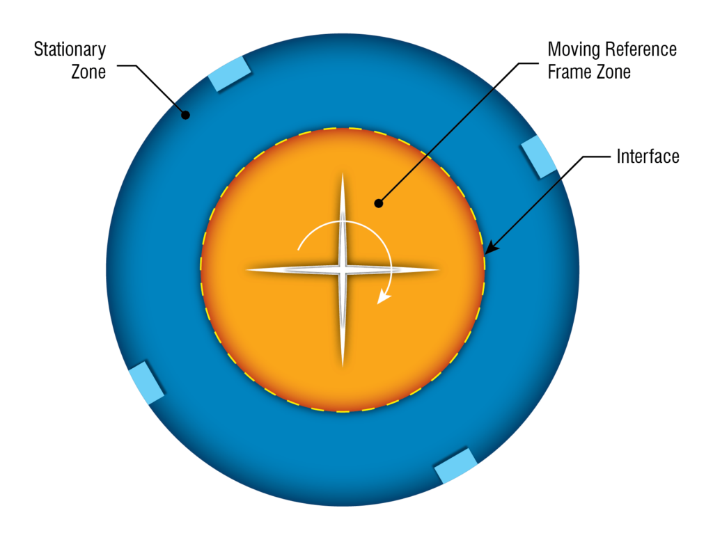
A steady-state approach used in industrial computational fluid dynamics to model challenges with rotating components is the Moving Reference Frame (MRF) approach. It is thought to need less computer power while being efficient enough for most industrial situations. This strategy’s underlying principles are straightforward but elegant. During the meshing phase, a small volumetric zone of mesh cells is produced around the spinning body, and the MRF zone encompasses this area.
The MRF zone is rotated around the body’s axis while the body remains still during the simulation phase. In a reference frame that rotates or moves at the same speed as the rotating or moving geometry, governing equations are solved. On a physical level, we see the flow field around the moving body while seated on it. The flow field becomes stable concerning the geometry as a result.
When a turbine is rotating, and we are on the ground, the flow field surrounding the turbine seems transitory to us. If we sat on a turbine blade and rotated with it, instead of seeing it from a distance, the flow field around us or the turbine would appear stable. CFD simulations use Multiple Reference Frames (MRF) to simulate fluid flow around rotating components or systems. It analyzes flow fields in turbine, pump, and fan systems.
MRF divides the rotating region into stationary reference frames for each rotating component. These computational domain reference frames have rotating speeds and axes. Each reference frame treats fluid flow as stationary, simplifying simulation. The MRF approach implies that fluid flow in each reference frame follows the Navier-Stokes equations with Coriolis and centrifugal forces. Each reference frame solves the equations separately, while boundary conditions at the interfaces couple the solutions.
The MRF technique makes flow field simulation in rotating component systems computationally efficient. It analyzes flow separation, recirculation, and vortex shedding around rotating machinery. Using MRF, the aerospace, automotive, and energy industries design and optimize rotating systems.
How can Multiple Reference Frames (MRF) CFD simulation be applied in Engineering and Industries?
Engineering and industry use MRF CFD simulation. Some examples:
Turbomachinery Design: Turbines, compressors, and pumps are designed and optimized using MRF models. Engineers can examine fluid flow around revolving blades, analyze performance characteristics, and optimize the design for efficiency.
A gas compressor that can constantly pressurize gases is known as an axial compressor. It is an airfoil-based rotating compressor where the gas or working fluid primarily flows axially or parallel to the axis of rotation. Rotating and stationary parts make up axial compressors. A stationary tubular casing houses a central drum driven by a shaft and held in place by bearings.
There are rows of airfoils between the drum and the casing, with each row alternately attached to the drum or the casing. A stage comprises two rows, one with moving airfoils and the other with stationary ones. The rotating airfoils accelerate the moving fluid in axial and circumferential directions, commonly called blades or rotors.
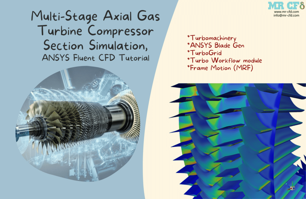
In this instance, a four-stage compressor with two rotors, two stators, and 120 blades in each stage was designed to simulate a high-performance, high-pressure compressor. According to the simulation findings, the flow speed changes clearly via passageways and declines in each step, and the pressure counter indicates that the pressure rises after each stage to give the system a P-ratio of 4.
The pressure contour on the blades and the speed triangles produced by rotating rotors demonstrates how the flow divided and stalled inside the system, respectively. The compressor’s efficiency was calculated using a software workflow scheme and reached 20%; the pressure decreased, which is also visible in the pressure contour.
Automotive Industry: MRF models analyze flow fields around rotating components such as engine fans, cooling systems, and turbochargers. This evaluates aerodynamic performance, heat transport, and design optimization for performance and fuel efficiency.
Aerospace: MRF simulations help design and analyze aircraft engines, propellers, and helicopter rotors. Engineers can simulate flow fields around spinning components to evaluate aerodynamic forces, heat transfer, and structural loads for safe and efficient operation.
Energy Systems: MRF simulations analyze wind and hydropower turbines. Engineers can optimize renewable energy devices by simulating rotating components to evaluate fluid dynamics, power output, and efficiency.
HVAC Systems: MRF simulations design and analyze HVAC systems. Engineers maximize system performance, air distribution, and energy economy by modeling flow fields around spinning components like fans and blowers.
The current Project mimics the operation of a ducted fan in a space. The study’s goal is to look into the performance and acoustic state. The door has a flow inlet with a velocity of 0.5 m/s—additionally, the wall outlet where the ducted fan is installed. With an angular velocity of 1000 rpm, the fan is rotating.
Two sound receivers have been placed in the space to examine the impact of the fan’s noise. The first is in front of the fan (receiver 1), while the second is at the entrance, close to the door. The outlines show that air enters the domain at a speed of 0.5 m/s, creates a wake around the fan zone, and exits the domain. Additionally, the duct functions as a suppressor and restricts sound propagation.
As a result, even if receiver 1’s sound pressure level is high, receiver 2’s within an acceptable range and won’t be an issue for the locals. The A-weighted pressure level supports the assertion and exhibits an 80 dB maximum or less than 120 dB. After all, the reported thrust force is 54.113455N.
MRF CFD simulations help engineers optimize designs, increase performance, and save engineering and industrial application costs by revealing fluid flow behavior around rotating components.
MR CFD services in the Multiple Reference Frames (MRF) Simulation for Engineering and Industries
- Various types of horizontal and vertical axis wind turbine
- Various types and situations of Tidal turbines (two and three and four-bladed)
- Simulation of turbomachinery includes (pumps, compressors, etc.)
- Airplane propeller CFD simulation
- Simulation turbofan and AFT fan
- Simulation of cavitation in Francis, Kaplan, and Pelton turbine
- Simulation of the rescue helicopter
- …
MR CFD (Multiple Reference Frame) CFD services specialize in engineering and industrial MRF simulations. These MRF simulation services can help with the following:
Consultation and Problem Definition: MR CFD services can help you understand your engineering problem and find MRF simulation applications. They can define simulation research objectives, boundary conditions, and requirements.
Geometry Preparation: MR CFD services can help prepare the 3D geometry of the system or component to be simulated. CAD model import, mesh generation, MRF simulation interfaces, and boundary conditions are possible.
Simulation Setup: MR CFD professionals can configure the MRF simulation by specifying reference frames, rotating speeds, fluid characteristics, turbulence models, and solver settings.
Numerical Simulation: MR CFD services use ANSYS Fluent or Open FOAM to do numerical simulations using the MRF method. They can simulate accurately and efficiently using discretization algorithms, convergence criteria, and solution monitoring.
Postprocessing and Analysis: MR CFD professionals may examine simulation results, create visualizations, and extract pertinent data for future studies. They reveal fluid flow characteristics, performance metrics, and other essential data.
Optimization and Design Improvement: Parametric studies, sensitivity analysis, and optimization algorithms can help MR CFD optimize rotating component designs. This improves performance, efficiency, and dependability.
Reporting and Documentation: MR CFD services can provide detailed reports on simulation approaches, results, and recommendations. Design validation, regulatory compliance, and reference can benefit from this material.
Engineering and industrial companies can benefit from MRF simulation experts by using MR CFD services. This can improve application design, performance, and cost.
Performance of horizontal axis tidal current turbine by blade configuration
ANSYS Fluent software is used in the current Project to model a horizontal-axis water turbine. Performance of horizontal axis tidal current turbine by blade configuration is a journal article used to compare and validate the results of the CFD simulation. A rotational motion is obtained in the turbine blades by colliding the water flow with the blades and applying a torque force, which causes a rotational flow for the surrounding water around the blades. The water passes the water turbine at a speed of 1 m.s-1.
Due to the three-dimensional architecture of the current model, the sections about the turbine blades are in the shape of airfoils of type S814. After the solution procedure, the software determines the amount of pressure coefficient applied to each turbine blade’s blades (Cp) based on the torque supplied to each turbine blade (T) blade.
Then, it was compared and validated using comparable values from the paper. The data in Table 2 of the paper served as the foundation for this comparison and validation process. The final value of the torque and pressure coefficient is determined using some of the data in the table as input or reference values.
HAWT and VAWT Comparison (Mesh Motion and MRF)

Engineers find modeling fluid flow via turbomachines to be one of the most fascinating uses for CFD. Turbomachines are spinning devices that transfer fluid flow’s kinetic energy to the rotation of other devices, such as turbines, or the opposite for pumps. The fifth installment of the Turbomachinery Training Course is this item.
In this course, you will discover how to use mesh motion and frame motion, two of the most well-known models for replicating the rotating motion of turbomachines. Mesh motion should be employed to accurately represent turbomachines with rotating axes that are not parallel to the flow direction (VAWT). In contrast, the frame motion technique is sufficient for replicating spinning structures like the HAWT.
FW-H and Broadband Noise Comparison on a HAWT
To examine the noise and sound generation caused by the rotating motion of a horizontal axis wind turbine (HAWT), we will compare the differences between two popular models for predicting acoustics in fluids, including Ffowcs Williams-Hawkings (FW-H) and the Broadband noise model.
Due to its internal workflow for calculating pressure and viscous tensions induced by the medium flowing through various solid structures, one of the fascinating uses of CFD for engineers is its capacity to anticipate sound waves and noises. This talent has several potential applications.
For instance, one may use CFD simulation to foretell the noise production of enormous buildings like wind turbines or even the slightest air disturbance brought on by a fly’s movements. The fifth installment of the Acoustic Training Course is this item. In this course, you will discover how to apply two of the most well-known models for forecasting the generation of acoustic waves inside a computational domain that contains a horizontal-axis wind turbine. Strong sound waves could injure human hearing up close due to the HAWT’s rotation and airflow passing over the structure. Thus, we have used acoustic models such as FW-H and Broad band noise inside ANSYS Fluent to examine this issue. Numerous findings and statistics demonstrate the advantages and disadvantages that each model may have over the others.
Acoustic (FWH) Investigation on a HAWT
With the use of ANSYS Fluent software, the acoustic performance of a wind turbine and the noises it produces at various places in its surrounding domain have been examined in this simulation in a transient condition. This turbine rotates around its horizontal axis at 72 radians per second. At a speed of 15 meters per second, a stream of air is moving in its direction. The turbine’s front and back provide several potential study locations. Acoustic (Broadband) Investigation on a HAWT, ANSYS Fluent CFD Simulation Tutorial Project, and this Project’s acoustic characteristics have been compared.
The points in this model can be established in the Acoustic Model-Define Receivers tab. It should be noted. In the Acoustic Model- Define Resources tab, you can choose the surface of the wind turbine as the noise source. The geometry of this issue was modeled using design modeler software and meshed using ANSYS meshing software. Tetrahedral components make up the final total, which stands at 2,696,011.
The fifth installment of the Acoustic Model Training Course is this item. Additionally, the areas of the turbine’s edge that are farthest from the hub and, as a result, have a greater magnitude velocity and are also in touch with the wind flow have higher values of the Surface dpdt RMS parameter. You can compare the Project’s parameters to the one provided in the description, which used the Broadband Model to solve the identical model. Finally, the final calculation’s contours, plots, pathlines, and FFTs are obtained and displayed as figures.
Duct Effect on HAWT Performance
In this research, Ansys Fluent is used to simulate the effects of ducts on HAWT performance in two separate instances. No duct is installed in one instance, whereas, in another, one is. The study aims to look into how the duct affects turbine performance. The tip-speed ratio is 2.5, and the multi-reference frame (MRF) module is employed.
ANSYS Fluent reports the torque the turbine blade produces around the y-axis for accurate assessment. The performance of wind turbines has improved significantly, by a factor of 63%, according to the results. To sum up, a tip-speed ratio of 2.5 significantly impacts but should be considered under various working circumstances.
Cavitation in a Cross-Flow Turbine
In this study, cavitation in a cross-flow turbine has been simulated using the CFD numerical simulation approach by Ansys Fluent software. Contrary to most turbines with axial or radial fluid flow, this one has cross-wise flow. Low head and high flow requirements call for this kind of turbine, which operates at a low speed.
There are three primary components to this Project. In the first example, there is no airfoil; however, in the second case, one is added at the entrance to prevent cavitation, and in the third case, the airfoil is angled differently from the second case by 15 degrees clockwise.
Case 1

Case 2
To avoid cavitation, the turbine’s inlet has been fitted with an airfoil in accordance with the prior case. This design can prevent cavitation because it is created on the airfoil, which can serve a protective function.
Case 3
The airfoil angle is rotated 15 degrees clockwise compared to the preceding scenario, and an airfoil is inserted at the turbine’s inlet to prevent cavitation. Investigating the impact of altering the airfoil angle on intensity is the goal of this step. Cavitation We can say that the rotation of the airfoil clock has benefited us because, based on the contours extracted from the volume fraction of the second phase, the quantity of cavitation is slightly less than in the prior instance.
Cavitation Flow Through an Axial Inducer
This simulation uses ANSYS Fluent software to explore cavitation flow through an axial inducer. We carry out this CFD project and do a CFD analysis to look at it. One of the phenomena is cavitation, where vapor bubbles form in the area of the fluid where the pressure is low. It’s a common misperception that the creation of steam bubbles and this phenomenon are solely caused by the liquid pressure reaching the vapor pressure (P_v).
However, this phenomenon is brought on by several different variables and characteristics. One helpful parameter in producing this phenomenon, for instance, is speed. Corrosion is one of the issues that might result from the cavitation phenomenon. Water pump corrosion is highly noticeable.
The sound and mechanical vibration that are created helps us to recognize this occurrence. It is possible to lessen this recurrence in several ways. Reducing the distance between the pump and the tank is one of the easiest ways to raise the pump’s intake pressure. Reduce the pressure drop and flow turbulence as an additional strategy. Due to the industry’s expansion, the demand for pumps with smaller sizes and faster speeds is more significant today. As a result, pump impeller suction performance needs to be improved.
To increase the pump’s suction performance and maintain the same impeller speed, inducers must be put in front of the main impeller. The inducer can enhance the pump’s suction performance by raising the inlet pressure to the impellers. The cavitation phenomenon is one of the most significant phenomena that should be considered in pumps. Inducers are employed in pumps for several purposes, one of which is to lessen cavitation.
The contours of liquid and vapor mass fraction, pressure, and velocity are obtained following the simulation. Additionally, streamlines are acquired around the inducer. The findings demonstrate that the pressure rises as the fluid enters the inducers. The impellers’ output and maximum inducer pressure are the same if this inducer is coupled to a pump. The performance of the pump’s suction is enhanced by an increase in the suction pressure at the inducer’s rear.
The velocity near the inducer is highest due to the angular velocity in this portion, according to velocity contours and streamlines. Additionally, the volume fraction contours demonstrate a decline in cavitation. Additionally, the velocity contours demonstrate that cavitation has diminished since the inducer has more water than vapor.
How to Model Multiple Reference Frames (MRF) inside ANSYS Fluent
ANSYS Fluent can model Multiple Reference Frames (MRF):
Geometry Preparation: Create or import the 3D geometry of your system or component in ANSYS Design Modeler or another CAD software. Make sure the geometry includes revolving and stationary sections.
Mesh Generation: Use ANSYS Meshing or another meshing program to mesh your geometry. Focus on mesh quality and resolution around spinning components where flow behavior is essential. Align the mesh with the rotating reference frame.
MRF Model Setup: In ANSYS Fluent, go to the “Model” area of the Fluent Launcher. Select “Multiple Reference Frames (MRF)” under “Models.”
Define Reference Frames: In the “Reference Frames” section, define the rotating reference frame(s) for rotating components. Give each reference frame its rotating speed and axis. Rotating components allow numerous reference frames.
Define Zones and Interfaces: Define your geometry’s MRF model zones. Give each zone its reference frame. For fluid exchange, define rotating-stationary zone interfaces.
Specify Fluid Properties: Define each zone’s fluid density, viscosity, and thermal conductivity. If necessary, define zone attributes.
Specify Boundary Conditions: Set your simulation’s inlet, outlet, and wall boundary conditions. Boundary conditions must match the MRF model and reference frames.
Solver Settings: Set the turbulence model, discretization schemes, convergence criteria, and solution methods. Consider rotating reference frame settings like MRF model convergence criterion and rotational speed.
Run the Simulation: Start the simulation and track convergence. Postprocessing and analysis can begin after the simulation converges.
Note that ANSYS Fluent versions differ in steps and choices. ANSYS Fluent documentation or support can provide thorough instructions for your version and application.
Revolving Rice Dryer Using DPM
In this research, a rotating rice drier device was simulated using the Ansys Fluent software’s Evaporating droplets with a one-way DPM model, and the results were then examined. The large chamber’s center has a porous tube with holes via which hot air enters the rice dryer. In a chamber rotating at 100 rpm, three million rice grains are injected with 15% moisture droplets.
They assemble around the porous tube in the chamber’s center after being injected with around three million rice particles through the entrance. When hot air is released from tube holes into the chamber, the evaporating process starts and causes the vaporizing material (H2o) to disperse. This may reduce the moisture of rice particles, which was 15% at first, and as a result, cause the diameter to decrease. Additionally, the chamber’s rotational speed quickens the flow of heated air.
The importance of the influence of fluid sloshing within the tank on the agility of floating equipment like ships, boats, and other craft is demonstrated by experimental and numerical research. We can name a few of the most significant laboratory research as follows:
1- Measuring a tank’s sloshing dynamics.
2. A Study of Sloshing Wave Impact Loads in the Shell Tank Model: An Experimental-Statistical Analysis.
3. The numerical sloshing results of the floating device holding the natural gas tank were verified Using an experimental result on a two-dimensional reservoir segment at a scale of 0.1 at two different filling heights.
4. To consider the impacts of the vibration brought on by the bump, look into the highest long-term sloshing pressures that can be given to the shell tank.
5-Experimental investigation of the pressure distribution caused by sloshing liquid in a rectangular tank.
Using ANSYS Fluent software, the current issue models how an earthquake would affect a dam. We carry out this CFD project and do a CFD analysis to look at it. Three-dimensional outlines corresponding to the volume fraction of each water and air phase are obtained after the solution procedure. The Iso-Surface tool then creates a three-dimensional image of the water flow’s free surface while considering the volume fraction value of 0.5 for each phase.
The earthquake has thoroughly impacted the water flow and has become entirely turbulent, according to the image taken from the free surface of the water flow. On the free surface of this water, the pressure, velocity, and kinetic energy counters of turbulence are measured.
An earthquake’s impact can also be seen through the analysis of variations in pressure and velocity on the free surface of the water. These outlines represent the final second of the simulation or the final second of the earthquake. Two-dimensional contours of static pressure and wall tension have also been measured on the ground surface and the dam’s surface. Creating a graph showing how the mean static pressure on the dam’s surface has changed over time is also possible.
Multiple Reference Frames (MRF) MR CFD Projects
Multiple Reference Frames (MRF) is a popular CFD method for modeling flow in rotating systems. MRF-based MR CFD projects can be used in many sectors. Some MR CFD projects:
Turbomachinery Design and Analysis: MRF simulations can examine the performance and aerodynamics of pumps, fans, compressors, and turbines. Simulations optimize the design, efficiency, and flow behavior of spinning systems.
Cavitation in a Radial Flow Pump

When a liquid’s pressure falls below its vapor pressure at a constant temperature, the cavitation phenomena take place. In this instance, the fluid transforms into vapor and forms a bubble. Cavitation is the name of this procedure. These bubbles will now burst if exposed to the pump’s high-pressure components. Due to the local vacuum created when the bubble bursts, the liquid surrounding it is forced to travel very quickly and under tremendous pressure in the direction of space.
This research aims to understand better the cavitation phenomenon that occurs inside pumps. We acquire three-dimensional contours of pressure, velocity, vapor phase volume fraction, liquid phase volume fraction gradient, and mass transfer rate gradient after the solution process. Additionally, we offer 3D velocity vectors. The contours of the mass transfer rate and vapor volume fraction that illustrate where the cavitation occurred are the most important findings of this investigation.
Acoustic in a Turbojet Intake Fan
The current issue uses ANSYS Fluent software to simulate the airflow within a turbojet and analyze the sound and acoustic wave it produces. The software analyzes sound or acoustic waves using an acoustic model. Additionally, according to the associated equations, the pressure and temperature of the airflow are 85416.92 pascals and 283.9524 K, respectively.
To thoroughly understand the issue, we offer the contour and vector of the domain’s velocity, pressure, temperature, acoustic power level (dB), and surface acoustic power level (dB) for the current simulation. In a nutshell, the acoustic aspects of the solution are more clearly discernible behind the fan and fan wall as air strikes them. The fan surface can also be used as a noise resource by measuring the Surface Acoustic Power Level (dB). Finally, the centerline plots of Acoustic Power Level (dB) and Surface Acoustic Power Level (dB) are obtained, which further aids in understanding the precise number of acoustic characteristics behind the fan.
Automotive Cooling Systems: MRF simulations can evaluate engine cooling, radiator design, and heat exchangers. These simulations maximize cooling efficiency, analyze fan designs, and evaluate system thermal behavior.
Wind Turbine Aerodynamics: MRF simulations can examine wind turbine aerodynamics. These simulations test performance, design factors, and blade shape for maximum power generation.
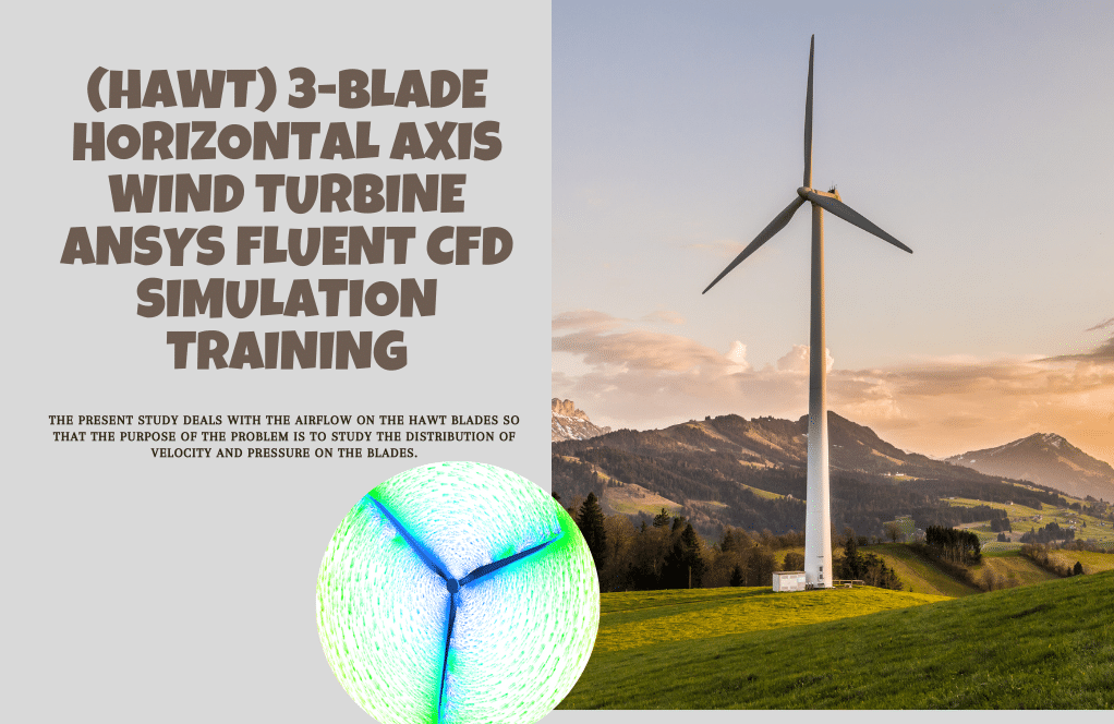
Helical Blade Wind Turbine, five different RPMs
The current issue uses the ANSYS Fluent program to simulate the airflow over a small-scale VAWT with helical blades. We carry out this CFD project and do a CFD analysis to look at it. One of these energies that has given researchers options is wind energy. Of all the renewable energy sources, this one is now growing at the fastest rate. Wind turbines are the machines that produce wind energy.
A wind turbine is a machine that transforms the rotor shaft’s rotational energy into the wind current’s kinetic energy. After the solution procedure generates pressure, velocity, and streamline-related two-dimensional and three-dimensional contours. The stagnation point is visible in the frontal region of the helical blade turbine, as seen by the pressure contour.
Furthermore, the flow separation causes a wake zone to form at the back of the turbine. It has also been determined how much torque power the turbine can transfer to the generator as output utilizing Fluent. These findings demonstrate that this turbine can deliver the highest torque at 80 rpm. This turbine, however, provides the highest torque when the TSR criterion is used in the test (TSR = 0.46). The angles of attack and profile must be created for this turbine to be as near the distance at TSR = 0.46.
The performance of this turbine can then be assessed according to TSR at various operating points, such as at constant rotational speed with various flow velocities. This makes it possible to locate the working conditions where the turbine performs at its highest level or produces the most torque.
Stirred Tank Reactors: MRF simulations can analyze fluid flow and mixing in chemical and pharmaceutical stirred tank reactors. Simulations optimize impeller design, flow patterns, and mixing efficiency.
HVAC Systems: MRF simulations can investigate HVAC airflow and temperature distribution. Simulations maximize air duct design, thermal comfort, and energy economy.
Marine and Propulsion Systems: MRF simulations can examine ship and submarine hydrodynamics and propulsion performance. These simulations improve propeller design, hull flow, and maneuverability.
Gas Turbine Combustion: MRF simulations help analyze gas turbine engine combustion characteristics. Simulations optimize fuel injection, flame propagation, and emission characteristics.
In contrast to radial turbines, where the fluid flows around a shaft like, in a watermill, an axial turbine has the working fluid flowing parallel to the shaft. An axial turbine is built similarly to an axial compressor but works in the other direction, transforming fluid flow into rotational mechanical energy.
The fluid is accelerated, given a swirl, and directed to the following row of turbine blades positioned on a turbine rotor by a set of static guide vanes or nozzle vanes. The most popular type of compressible fluid turbines are axial-flow turbines. The steam turbine was created many years before the gas turbine.
Axial-flow turbine technology, employed in gas turbines, is a steam turbine technology development. Numerous cooling strategies have been needed due to the trend toward high turbine intake temperatures in gas turbines. Modern axial-flow turbines are built with a high work factor to reduce fuel consumption and less noise.
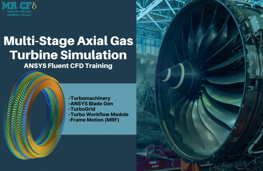
In this instance, a four-stage compressor with two rotors and two stators with 130 blades in each stage was designed to simulate a high-performance, high-pressure compressor in operation. According to the simulation findings, the flow speed changes across passages and increases in each step, while the pressure counter indicates that the pressure decreases after each stage, giving the system a P-ratio of 0.8.
The pressure contour on the blades and the speed triangles produced by rotating rotors demonstrates how the flow divided and stalled inside the system, respectively. A software workflow scheme was used to calculate the system’s efficiency, which produced a number for the turbine of 18%.
These are several MRF-based MR CFD projects. Industry, application, and engineering requirements determine project scope and objectives. MR CFD services can help with these projects, providing accurate simulations and insights for design optimization and performance enhancement.
Multiple Reference Frames (MRF) Application in Industrial Companies
MRF is used in many industrial industries. Industrial MRF uses include:
Rotating Machinery: Pumps, fans, compressors, and turbines are designed and analyzed using MRF. It lets engineers mimic these machines’ flow behavior and performance under varied operating situations to optimize design and efficiency.
HVAC Systems: MRF analyzes HVAC systems. It helps engineers understand building airflow, temperature, and thermal comfort. This knowledge is essential for building energy-efficient HVAC systems with high indoor air quality.
Chemical and Process Industry: Stirred tanks, reactors, and mixers are simulated using MRF. Engineers can optimize system design and process efficiency by studying fluid flow, heat transfer, and species transport.
Automotive Industry: MRF simulates vehicle aerodynamics, especially in spinning components like wheels and cooling fans. Engineers can evaluate airflow patterns, drag forces, and cooling performance to build more aerodynamic and efficient cars.
Power generation: MRF analyzes gas turbines and wind turbines. It lets engineers optimize design and efficiency by studying these systems’ fluid flow, heat transport, and power generation.
Aerospace Industry: MRF simulates flow around propellers, rotors, and engine fans. It helps engineers create quieter, more efficient aircraft by analyzing these components’ aerodynamic performance, noise generation, and efficiency.
Marine and Offshore Industry: MRF analyzes ship propellers, undersea vehicles, and offshore platforms. It lets engineers optimize these systems’ hydrodynamics, propulsion performance, and structural behavior for safe and efficient operation.
These are some ways industrial companies use MRF in engineering and design. MRF uses, and benefits vary by industry, company, and Project. MRF simulations help industrial organizations improve product performance, energy efficiency, cost, and design.
MR CFD Industrial Experience in the Multiple Reference Frames (MRF) Field
Some examples of Multiple Reference Frames (MRF) industrial projects recently simulated and analyzed by MR CFD in cooperation with related companies are visible on MR CFD Website.
You may find the Learning Products in the Moving Reference Frame (MRF) CFD simulation category in Training Shop. You can also benefit from the Multiple Reference Frames (MRF) Training Package, which is appropriate for Beginner, Intermediate, and Advanced users of ANSYS Fluent. Also, MR CFD is presenting the most comprehensive Multiple Reference Frames (MRF) Training Course for all ANSYS Fluent users from Beginner to Experts.
Our services are not limited to the mentioned subjects. The MR CFD is ready to undertake different and challenging projects in the Combustion modeling field ordered by our customers. We even carry out CFD simulations for any abstract or concept Design you have to turn them into reality and even help you reach the best strategy for what you may have imagined. You can benefit from MR CFD expert Consultation for free and then Outsource your Industrial and Academic CFD project to be simulated and trained.
By outsourcing your Project to MR CFD as a CFD simulation consultant, you will not only receive the related Project’s resource files (Geometry, Mesh, Case & Data, …), but also you will be provided with an extensive tutorial video demonstrating how you can create the geometry, mesh, and define the needed settings (preprocessing, processing, and postprocessing) in the ANSYS Fluent software. Additionally, post-technical support is available to clarify issues and ambiguities.

