CFD Project Outsourcing
Outsource your CFD project to the MR CFD simulation engineering team. Our experts are ready to carry out every CFD project in all related engineering fields. Our services include industrial and academic purposes, considering the ANSYS Fluent software's wide range of CFD simulations. By outsourcing your project, you can benefit from MR CFD's primary services, including CFD Consultant, CFD Training, and CFD Simulation.
The project freelancing procedure is as follows:
An official contract will be set based on your project description and details.
As we start your project, you will have access to our Portal to track its progress.
You will receive the project's resource files after you confirm the final report.
Finally, you will receive a comprehensive training video and technical support.
What is Multiphase Flow?
Multiphase flow is the kind of flow that occurs most frequently in nature and technology. A phase is understood in the thermodynamic sense as a solid, liquid, or gas-like state that can coincide in one-component or many-component systems. Storm clouds drifting with raindrops and hailstones, a burbling stream in the mountains, a snow-dust avalanche, and a volcano cloud are impressive examples of natural multiphase flows. Multiphase flows are often an important heat and material transport method in power stations and chemical technology. Two-phase flows determine the processes in steam generators, condensation, and cooling towers of steam power stations. Multiphase multicomponent flows extract, transport, and treat oil and natural gas. These flows are also extensively involved in distillation and rectification processes in the chemical industry. Multiphase flows generally manifest themselves as unsteady processes with a chaotic character. Therefore, to a much greater extent than for turbulent flows, a formal description requires using average states, statistical methods, and scaling laws to make quantitative statements about the expected phenomena, such as pressure drops and phase distributions. The very different forms and structures, even in the simplest geometries, such as pipes and channels of the constant cross-section in gas-liquid or gas-solid flows, make a consistent mathematical, physical description of multiphase flows difficult. The effect of gravity is considerable. In addition, interfacial tensions and electrostatic forces in solids are essential. Multiphase flows can fundamentally be described in two different ways.
On the one hand, the multiphase flow can be considered a moving continuum of phases penetrating each other, whereby each phase is present at every location to a certain extent. This model is helpful if the large-scale behavior of a multiphase fluid is to be described. On the other hand, the motion in each phase can be described separately, with the coupling between the phases at the interfaces of particular importance. This is expressed mathematically by computing the motion of the interfaces in detail by specific mathematical methods. This consideration is advantageous if interface interactions, such as mass fluxes, govern the processes.
The simultaneous movement of several phases, such as liquids, gases, or solids, within a system is called multiphase flow. In a multiphase flow, two or more phases coexist and communicate continuously or dispersedly. Many industrial, environmental, and ecological processes involve this flow.
In a multiphase flow, the phases can have a variety of physical characteristics, including density, viscosity, and thermal conductivity. The distributions of the phases’ temperatures, concentrations, and velocities can also vary. Multiphase flow examples include gas-liquid (for instance, air-water), liquid-liquid (for instance, oil-water), gas-solid (for instance, air-particle), and three-phase (for instance, gas-liquid-solid) flows.
Phase separation, mixing, dispersion, coalescence, evaporation, condensation, and the movement of solid particles are just a few of the complex interactions and phenomena that can occur in multiphase flow phenomena. Numerous engineering applications, including chemical processes, the petroleum industry, nuclear reactors, food processing, environmental research, and more, depend on understanding and anticipating multiphase flow behavior.
Numerical simulation techniques like Computational Fluid Dynamics (CFD) are frequently used to simulate and analyze multiphase flows. Engineers and scientists can use these models to examine the flow characteristics, phase distribution, pressure drop, heat transfer, mass transfer, and other pertinent aspects. The numerical models are also validated and supplemented by experimental methods like flow visualization, laser-based diagnostics, and particle tracking. In general, multiphase flow is a large, complex, and diverse field. Designing effective systems, guaranteeing safe and dependable operations in various industries, and optimizing processes depend on understanding multiphase flow behavior.
How can Multiphase Flow CFD simulation be applied in Engineering and Industries?
Simulations using computational fluid dynamics (CFD) for multiphase flow have many uses in engineering and industrial fields. Following are some instances of multiphase flow CFD simulations in use:
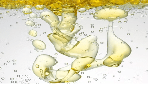
Chemical and Process Engineering: Multiphase reactions, mixing, and separation processes in chemical reactors, distillation columns, crystallizers, and other equipment are modeled using CFD models. It supports improving product quality, process effectiveness, and equipment design.
Pharmaceutical and Biomedical Engineering: Multiphase flow simulations help analyze drug delivery systems, aerosol inhalation devices, and blood flow in vessels in pharmaceutical and biomedical engineering fields. It helps with fluid-particle interactions, particle deposition, and drug dispersion comprehension and optimization.
Food and Beverage Industry: Multiphase flows in food processing activities, such as mixing, emulsification, spray drying, and fermentation, are studied using CFD models. It aids process parameter optimization, product quality improvement, and food safety assurance.
Environmental Engineering: Multiphase flow simulations examine the processes involved in wastewater treatment, pollutant dispersion in the atmosphere, and sediment transport in rivers. Understanding environmental impacts, creating mitigation strategies, and improving treatment systems are all made more accessible by it.
Power Generation: CFD models aid in analyzing multiphase flows in power plant systems, such as cooling systems, fuel spray combustion in gas turbines, and boiling and condensation in steam generators. It supports efficiency improvement, pollution reduction, and safe operation.
Mining and Minerals Processing: In mining and minerals processing activities, multiphase flow simulations are studied in partial transport, flotation, and solid-liquid separation processes. It enhances process effectiveness, reduces water use, and optimizes recovery rates.
These are a few examples of multiphase flow CFD simulations’ technical and industrial applications. Multiphase flow simulations can be used in various sectors due to their adaptability, which enables engineers and researchers to comprehend complex flow phenomena better, streamline procedures, and enhance system performance.
MR CFD services in the Multiphase Flow Simulation for Engineering and Industries
With several years of experience simulating various problems in various CFD fields using ANSYS Fluent software, the MR CFD team is ready to offer extensive modeling, meshing, and simulation services. Simulation Services for Multiphase Flow simulations are categorized as follows:
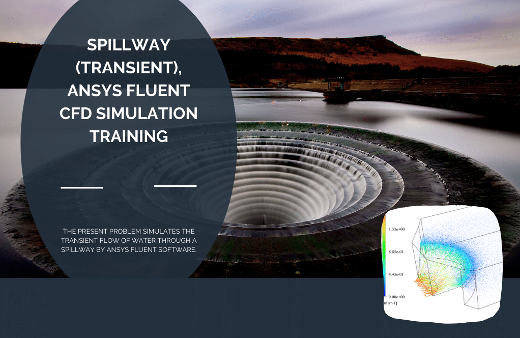
- Simulation of free surface and open channel flow of various spillways
- Simulation of improving jet loop reactor performance and increasing gas holdup using various methods
- Predicting entrainment ratio in two-phase ejector
- CFD Simulation of Gas and liquid separator
- CFD Simulation of Gas-oil filling in an automobile fuel tank
- CFD Simulation of Droplet releasing
- CFD Simulation of Droplet Pumps
- CFD simulation of Desalination of Salty water with solar energy
- CFD Simulation of Multiphase simulation of heat transfer with freezing and melting operations
- CFD Simulation of Water slushing in tank and damn (during vibration and earthquake)
- …
MR CFD is a top provider of multiphase flow simulation services for engineering and other industries. They provide complete solutions for analyzing and optimizing multiphase flow systems thanks to their experience in computational fluid dynamics (CFD). Some of the services they offer include:
Multiphase Flow Modeling: MR CFD is an expert in creating precise and effective numerical models for multiphase flow simulation. To understand the behavior of complicated multiphase systems, they consider elements including phase interactions, phase distribution, turbulence, heat transmission, and chemical processes.
System analysis and optimization: MR CFD aids in analyzing and improving multiphase flow systems for engineers and businesses. They shed light on flow properties, pressure drop, phase distribution, mixing effectiveness, heat transfer, etc. Clients can do this to increase product quality, decrease energy use, and improve system performance.
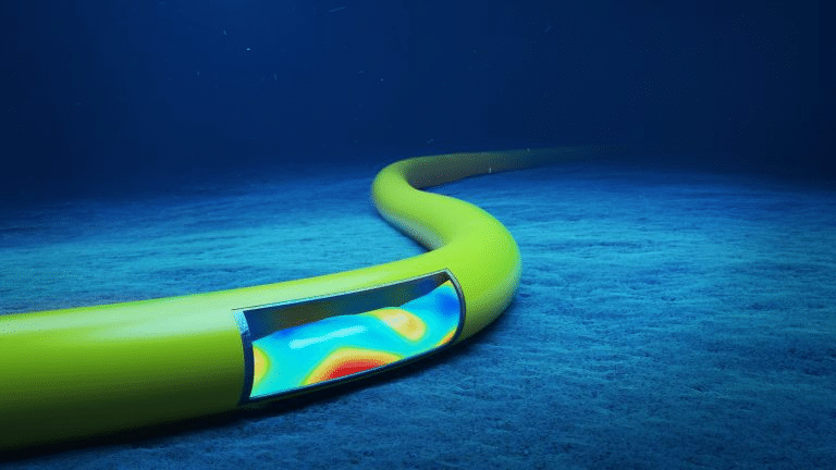
Process Optimization: In various industries, including oil and gas, chemical, pharmaceutical, food and beverage, and more, MR CFD aids in the optimization of multiphase flow processes. They can locate bottlenecks, increase mixing effectiveness, decrease waste, improve reaction kinetics, and improve process performance by simulating and examining the flow behavior.
Troubleshooting and Performance Improvement: MR CFD aids in resolving multiphase flow problems like flow instabilities, phase separation, pressure drop inconsistencies, and equipment performance restrictions. Through simulation and analysis, they can pinpoint the underlying issues, implement fixes, and improve the system’s performance and dependability.
Customized Solutions: MR CFD offers solutions specially crafted to meet the unique requirements of its clients in the engineering and industrial sectors. They collaborate closely with clients to comprehend their needs, create sensible simulation tactics, and provide accurate and trustworthy outcomes.
Engineers and businesses may improve system performance, assure effective and dependable operations, and optimize processes with MR CFD’s comprehensive Multiphase Flow Simulation services.
How to Model Multiphase Flow inside ANSYS Fluent
You can generally take the following actions to represent multiphase flow inside ANSYS Fluent:
– Describe the Multiphase Model: The Volume of Fluid (VOF), Eulerian, and mixing models are just a few of the multiphase models available in ANSYS Fluent. Select the suitable model based on your multiphase flow system’s features.
– Establish the Geometry: In ANSYS Fluent, import or build the geometry for your multiphase flow system. Make that the boundaries and interfaces between the various phases are all accurately stated in the geometry.
– Defining the Phases: List the characteristics of each phase that is a part of the multiphase flow, including density, viscosity, surface tension, and other pertinent factors. Give each process the supplies it needs.
– Define the Flow Conditions: Establish the beginning and boundary conditions for each phase while defining the flow conditions. At the inlets, outlets, and other boundaries, this includes stating the velocity, pressure, temperature, and mass flow rates.
– Specify the Multiphase Interactions: Specify the interactions between the phases in the selected multiphase model. This could involve phase separation, coalescence, breakage, or phase change (evaporation or condensation). Define the pertinent models and parameters as necessary.
– Pick Numerical Methods: Pick the best numerical techniques for resolving the multiphase flow system’s governing equations. The discretization schemes, turbulence models, and convergence criteria are all chosen in this process.
– Run the Simulation: Simulate by configuring the solver’s parameters, including the time step size, the convergence standards, and the maximum number of iterations. Start the simulation and monitor the solution’s convergence and development.
– Postprocessing: After the simulation, examine and display the outcomes. ANSYS Fluent offers various postprocessing capabilities to investigate characteristics like phase distribution, velocity profiles, pressure contours, and other pertinent values.
It’s crucial to remember that based on the multiphase model you choose and the features of your system, the precise stages and settings may change. ANSYS Fluent offers thorough documentation and tutorials to assist you in modeling multiphase flow.
Multiphase Flow MR CFD Projects
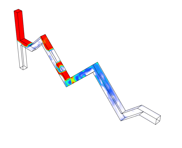
– Oil and Gas Industry: MR CFD has participated in projects involving multiphase flow simulations in the transportation and production of oil and gas. They have modeled complex flow behavior in pipelines, separators, and offshore platforms to maximize production effectiveness, prevent instability, and ensure safe operations.
– Chemical Industry: Projects in the chemical industry have been done by MR CFD, which involved simulating multiphase flow systems in reactors, mixers, and separation units. Through realistic phase interactions and flow behavior modeling, they have assisted clients in improving reaction kinetics, mixing effectiveness, and product quality.
– Pharmaceutical Industry: To simulate and improve multiphase flow processes in medication formulation, crystallization, and filtering, MR CFD has worked with pharmaceutical businesses. They have offered insights into phase distribution, particle size distribution, and heat transmission to improve process effectiveness and product quality.
– Food and Beverage Industry: MR CFD has experience with multiphase flow simulation projects in this sector. They have studied flow behavior in mixing tanks, heat exchangers, and spray drying systems to increase product homogeneity, assure effective heat transfer, and optimize process variables.
– Renewable Energy: MR CFD has performed multiphase flow simulations for renewable energy applications. Examples include modeling two-phase flow in geothermal systems and multiphase flow in wave energy converters. They have contributed to improving energy conversion efficiency, reliable and sustainable operations, and system design optimization.
These are only a few instances of the multiphase flow projects that MR CFD has effectively finished. With their proficiency in multiphase flow modeling and computational fluid dynamics (CFD), they offer specialized solutions to fulfill customers’ unique requirements across various sectors.
As for modeling multiphase flows in ANSYS Fluent, it has four modules for modeling multiphase flow, and each model has its advantages, disadvantages, and limitations. These modules include Volume of fluid (VOF), Mixture, Eulerian and Wet steam. Wet steam is available only for incompressible fluid flow and density-based models.
Volume Of Fluid (VOF) Model
The VOF model is used for multiphase flow. The boundary or contact area between two phases is clearly defined; in this multiphase model, the different phases do not mix. Free-Surface, laminar flows, jet disintegration phenomena, and movement of large bubbles into the liquid, pool boiling, fluid falling like a waterfall, spillways are examples of using the VOF model.
Multiphase flows are frequently modeled using the Volume of Fluid (VOF) method in computational fluid dynamics (CFD). It is beneficial for modeling the contact between two or more immiscible fluids.
The volume percentage of each fluid is monitored across the whole computational domain in the VOF approach. The distribution of the volume fractions determines the position of the sharp interface that represents the fluid interface. Phase separation, mixing, and surface tension effects can all be accurately predicted using the VOF approach.
The VOF technique has the following key components and actions:
– Interface Tracking: By allocating a volume fraction value to each cell in the computational domain, the VOF approach tracks the location of the fluid interface. A cell occupied by one fluid has a value of 1.0, while a cell occupied by another fluid has a value of 0.0.
– Conservation Equations: The VOF approach resolves each phase’s mass, momentum, and energy conservation equations. These equations consider the mass, momentum, and energy exchange across the interface and interfacial forces like surface tension.
– Interface Reconstruction: The VOF method uses interface reconstruction techniques to describe the interface between the fluids precisely. These methods use the volume fraction values in nearby cells to determine the interface’s form and location.
– Advection Scheme: To move the volume fraction values throughout the computational domain, the VOF approach employs an appropriate advection scheme. This guarantees that the interface will move correctly and that fluid behavior will be accurately represented.
– Surface Tension Modeling: Using the VOF approach, surface tension effects at the fluid interface can be modeled. Surface tension forces can be accounted for using various models, including the Young-Laplace equation and the Continuum Surface Force (CSF) model.
– Postprocessing: After the simulation, the findings can be analyzed and visualized using postprocessing techniques. This could entail measuring the interface’s size and location, determining flow rates, or observing how the fluids mix.
Many CFD software programs, such as ANSYS Fluent, Open FOAM, and COMSOL Multiphysics, support the VOF approach. It is a flexible and effective technique for modeling multiphase flows and is frequently used in various sectors, including oil and gas, chemical processing, and automobile engineering.
Humidification Dehumidification (HDH)
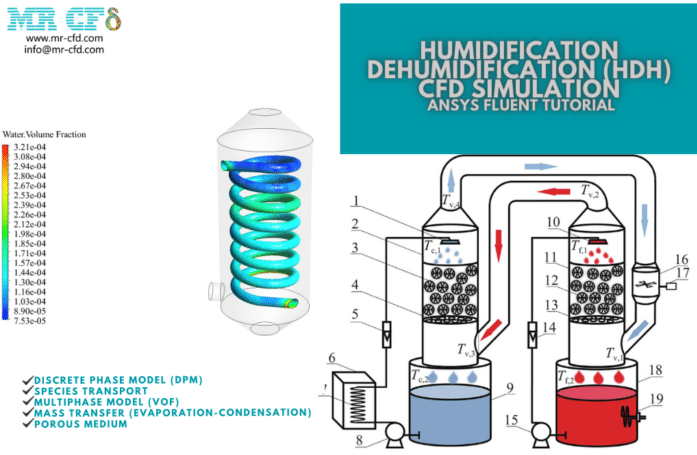
The dehumidifier’s (condenser) spiral tubes are where the cold water enters. The steam inside the shell is then used to heat the water. The water inside the tube continues to receive heat until the steam condenses, at which point it is heated. This heated water enters the humidifier (the evaporator) and is sprayed onto the evaporator’s filter plates. Wet steam or humidified air is created when these droplets are combined with the dry air that exits the condenser. Pure steam is produced, and any impurities settle to the bottom of the evaporator. A heater reheats this pure steam before it enters the condenser.
As previously indicated, the condenser shell’s interior is now in touch with the cold feed water pipes. The steam is humidified, or purified water is distilled from it. The two steps of the system’s process are humidification and dehumidification. For this issue, two simulations have been run. In the first simulation, humidification was studied. Dry air rises from the chamber’s bottom to its top. Hot salt water is sprayed via several pores inside the chamber simultaneously. After evaporating, the droplets in the membrane portion of the chamber clash with the airflow to create humid air.
This steam is salt-free and unadulterated. Dehumidification was the subject of the second simulation. The chamber is filled with the flow of moist air produced in the previous phase. Spiral tubes are thought to transport the cooling water flow inside the chamber. Freshwater is produced when hot steam touches the spiral tube’s cold surface and condenses.
The contours relating to the mass fraction of air and water vapor and the concentration of discrete particles have been acquired following the conclusion of the first simulation. The results only apply to the final second of the simulation because it is unstable. Two animations have also been created to better comprehend the solutions to this challenge. On a two-dimensional plane, one looks at the contour of changes in the mass fraction of produced water. The compartment is being traversed by the plane. The other uses particle tracking to examine how water droplets spread over time.
The findings demonstrate that droplets are routinely shot downward from the chamber’s higher apertures in preparation for meeting dry air. The outcomes additionally demonstrate that water is gradually created over time and travels toward the upper exit of the chamber.
Given that the purpose of the simulation was to produce humid air, this demonstrates that it was done correctly. Additionally, the mass fraction of produced water over time has been plotted. This plot demonstrates how steam builds up over time. After the second simulation, it was possible to generate two-dimensional contours for the following variables: velocity, temperature, mass transfer rate (from steam to water), and volume proportion of water and steam. This simulation has been running continuously and without regard to time.
The findings demonstrate the phase transition in the areas surrounding the cold spiral tube. The temperature contour reveals that the vapor temperature has dropped and fallen below the saturation point near the cold pipe. Condensation, or the conversion of vapor to water, must therefore occur.
The mass transfer rate’s contour also effectively demonstrates that the phase transition occurs in areas where the temperature is lower than the saturation temperature. When a phase transition from liquid to vapor occurs, the sign changes from negative to positive (indicating the phase transition from liquid to vapor). The contour of water and vapor volume fraction changes also confirms condensation. The results show that the areas closest to cold pipes are where the most produced water is found.
A numerical investigation of the effect of surface wettability on the boiling curve
The current issue uses the ANSYS Fluent program to simulate nucleate boiling inside a vertical channel. The reference work, “A numerical investigation of the effect of surface wettability on the boiling curve,” served as the foundation for the simulation. It compares and validates its findings with those in the article. It is investigated and examines how surface wettability affects the pool boiling curve.
The saturation temperature of the water inside the canal is thought to be 373K. To accommodate variations dependent on the paper, the channel has a heat plate (bottom wall) with a range of temperatures (from 375 to 475 K). The water is already boiling inside the channel at a temperature of 100 degrees centigrade, so the process will begin when it touches the hot bottom wall. The boiling nucleate will form if it is large enough, and a hot bubble will split from the heated surface.
The outcomes of the present work are compared and validated with the results produced by the article after this simulation. Figure 8’s illustration illustrates how the changes in the fluid’s transmitted heat flux depend on these changes. The Project at hand aims to achieve a contact angle of 60 degrees.
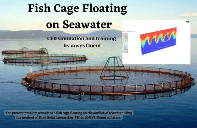
The Fluid Solid Interaction (FSI) method in the ANSYS Fluent program is used to model a fish cage floating on the surface of seawater in the current challenge. We carry out this CFD project and do a CFD analysis to look at it. After the solution method, we receive the Fluent and Transient Structural software findings. The final 0.05 seconds of the simulation are relevant to all results. We obtain deformation, strain, and stress contours on the body surface of this fish breeding cage using transient structural software.
Using the Fluent software, we produce two-dimensional volume fraction contours of the water, air, pressure, and velocity on the middle plate (the same as the symmetry plate). We also show the contour of the pressure applied to the body’s surface of this fish breeding cage. Additionally, attempts have been made to get the seawater wave’s surface and then depict two-dimensional pressure, velocity, and velocity vector contours. The waves produced by open channel wave BC can also be viewed in volume fraction contours. Furthermore, the thin bars connecting the top and bottom holders exhibit the greatest distortion.
Application of the Shiono and Knight Method in compound channels with non-prismatic floodplains
The current issue involves utilizing the ANSYS Fluent program to simulate a two-phase flow in a compound channel. We compare and validate the simulation’s results with those in the reference article “Application of the Shiono and Knight Method in compound channels with non-prismatic floodplains,” on which it is based. The primary channel through which the natural flow of water travels makes up the majority of natural rivers (floodplains). However, when the water flow increases, one or more flood layers are developed nearby as a floodplain. Therefore, we can suppose a channel whose cross-section does not include a fundamental geometric feature.
Compound channels are the name given to these kinds of channels. The current simulation aims to examine two-phase flow dynamics in a compound channel that includes air and water. The data in Figure 1-c of the reference publication served as the foundation for the compound channel geometry. We use the multiphase Volume of the Fluid model (VOF) in the Fluent program because the current model comprises two phases of air and water. As a result, the surface tension force between the air and water is defined as 0.072 N.m-1. The open channel flow model should also be applied because the water flow at the canal’s inlet portion is limited to a particular height or level. Thus, 0.0357143 m is the height of the water at the intake section.
The figure in Figure 10-a of the cited work is the foundation for validating the current paper. The profile of velocity value changes along the channel cross-section is depicted in this diagram. This profile was collected 14 meters from the canal entrance. Additionally, changes in the mixed flow’s vertical velocity and the line corresponding to the surface of the interface between the two phases of air and water have been discovered.
Because it can be assumed that the volume fraction of each phase at the interface between the two phases is roughly equal to 0.5, the iso-surface command can create a plane in which the volume fraction of water or air is 0.5 to find the line corresponding to the interface between the two phases. Figure 3 compares and validates the numerical work results with the experimental work findings from the article. These diagrams demonstrate that the velocity is greater in the area above the compound channel’s center than at other spots.
Two-dimensional contours relating to each air and water phase’s pressure, velocity, and volume fraction are obtained after the solution procedure. At a distance of 14 m and in a portion parallel to the channel inlet section (X-Y plane), two-dimensional contours are produced.
Effects of curvature radius on separation behaviors of the Hydrocyclone with a tangent-circle inlet
The current issue uses the ANSYS Fluent program to simulate the two-phase flow of air and water inside a hydrocyclone. The reference article, “Effects of curvature radius on separation behaviors of the Hydrocyclone with a tangent-circle inlet,” served as the foundation for the simulation. Comparing and validating its findings with those in the article. The results of the current work are compared to and validated against those acquired by the paper after this simulation. Figure 10’s illustration illustrates how the fluid mixture’s axial velocity varies depending on the hydro cyclone’s radial position to serve this goal.
VOF to DPM, Water Jets Impingement
To remove heat from a surface or enhance heat transmission, high-velocity fluid jets are directed onto the surface using the water jet impingement method. The aerospace, food processing, metal forming, and electronic cooling industries are just a few of the ones that employ them.
Simulations are used in computational fluid dynamics (CFD) to clarify and improve jet impingement processes. To accurately depict the multiphase flow behavior and particle tracking in jet impingement, ANSYS Fluent offers VOF to DPM simulations. The VOF method uses a precise model of the fluid-air interface to capture the complex interactions between the high-velocity jets. Using the DPM model, it is possible to identify and follow droplets frequently present during jet impingement processes.
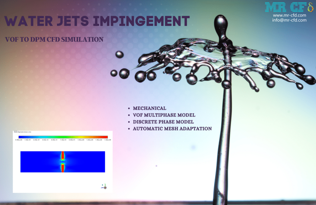
A planar liquid surface is created when the two jets collide, as seen by the findings. The force of the jet’s impact also causes some particles to develop. As the liquid surface in the middle of the domain expands over time, additional particles are created on the body of jets and build up on top of the expanding water surface. They have varied sizes, and their velocity diminishes as they approach the liquid surface.
In addition, it is clear from the image of the mesh inside the domain that it is substantially smaller at the water-air contact than in other areas. This is because a precise calculation of the surface tension at the water-air interface is necessary to capture the flow instabilities that lead to droplet formation. Otherwise, the droplet’s production location, diameter, and velocities would not be consistent with real physics.
Mixture Model
The Mixture model is a simplified Eulerian model based on a small Stokes number assumption. This model is used in multiphase mixtures where the phases have different velocities but are in equilibrium over small spatial longitudinal scales or multiphase mixtures with very strong homogeneous coupling and the same velocity for different phases. This model solves a volume fraction transport equation for each defined secondary phase. This model applies to the bubble, slurry (non-Newtonian), and water droplets regarding flow regime. Practical examples of this model include deposition phenomena, cyclone separators, low particle carrier flows, and bubble flows carrying a low gas volume fraction. The mixture model, like the VOF model, has a single fluid perspective but differs from the VOF model; first, the mixture model allows the phases to penetrate each other, and secondly, the mixture model allows the phases to move at different velocities if the concept of Slip Velocity is used.
A mixture is any combination of two or more immiscible fluids that coexist inside a computational region in the context of multiphase flow simulations. Different characteristics of the liquids in a combination may include composition, density, and viscosity. It’s crucial to precisely model each fluid phase’s behavior and interactions while modeling a combination. In multiphase flow simulations, modeling mixtures is essential for the following reasons:
– Phase Distribution: It is necessary to ascertain how each fluid phase is distributed within the computational domain. The most common way to accomplish this is by monitoring the volume fractions of each phase using techniques like the Volume of Fluid (VOF) or Eulerian-Eulerian approaches.
– Interfacial Dynamics: The interface between the various fluid phases is critical in mixture simulations. To effectively model the behavior of the mixture, surface tension forces, interfacial shear stresses, and mass transport across the interface must be considered.
– Phase Properties: The density, viscosity, and composition of each fluid phase in the mixture can vary. These characteristics, such as flow patterns, phase separation, and mixing, might affect the behavior of the mixture as a whole. For accurate simulations, phase properties must be adequately characterized.
– Flow Regimes: Different flow regimes may exist within the mixture depending on the relative velocities and concentrations of the fluid components. These could be annular flow, slug flow, stratified flow, or dispersed flow. Predicting the mixture’s overall behavior requires an understanding of the flow regime.
– Heat and Mass Transfer: Heat and mass transfer between the fluid phases can be substantial in many mixed simulations. This includes natural occurrences such as chemical reactions, evaporation, condensation, and dissolution. These transfer processes must be modeled to represent the mixture’s overall behavior accurately.
– Solver and Numerical Methods: The accuracy and effectiveness of modeling mixtures can be affected by the solver and numerical methods selected for the simulation. Careful consideration should be given to selecting suitable solvers, discretization strategies, and convergence criteria to achieve dependable and accurate findings.
Mixture simulations are frequently employed in many industries, including chemical processing, oil and gas, pharmaceuticals, and environmental engineering. Engineers and academics can obtain critical insights into the functionality of multiphase systems and improve their design and operation by precisely simulating the behavior of mixtures.
Productivity estimation of single-slope solar still: Theoretical and numerical analysis

In general, evaporation is a surface process on the liquid surface at any temperature. In this simulation, a single slope solar still with a predetermined volume of water and height is created. The glass-covered, sloping surface of the solar still transfers heat from the sun to the water’s surface. Surface evaporation occurs as heat is transferred from solar radiation that passes through the glass to the water.
Two-dimensional contours of temperature, velocity, and mass transfer rate between two phases (surface evaporation rate), air volume fraction, liquid water volume fraction, and water vapor volume fraction were acquired after the solution process. The water surface of the solar still chamber dries out with time, as can be observed from the contours. As a result, inside the chamber, a portion of the area above the water surface is occupied by water vapor.
The results of Table 3 of the publication above serve as the foundation for validating the current simulation. The model evaporation rate reported in the research is used to compare and validate the amount of surface evaporation rate in the two simulations. This evaporation rate number represents the most significant mass transfer rate between the two liquid and water vapor phases. The temperature of the glass is 30 °C in the first scenario. In the first instance, the glass is 40 degrees Celsius, and the water is 50 degrees Celsius, whereas in the second instance, the glass is 40 degrees Celsius, and the water is 50 degrees Celsius.
Thermal Management of Battery Using Nano Fluid
The current issue uses Ansys Fluent software to simulate the Thermal Management of Battery Using Nano Fluid (Two-Phase). A Dual-Potential MSMD (multiscale multidomain) battery model is involved in this simulation. A battery can typically convert electrical energy into chemical energy for storage. The chemical energy is transformed into electrical energy if the battery’s current is needed, and the electrical energy is then transformed back into chemical energy during battery charging. Additionally, heat can be produced by various processes, such as internal losses from joule heating and local electrode overpotentials, entropy from cell reactions, mixing heat, and side reactions.
To help with the scaling up of Li-ion material & electrode designs to entire cell & pack designs, a modular, efficient battery simulation model (MSMD model) was previously proposed. This model captured electrochemical interaction with 3-D electronic current pathways and temperature response. The flexible and extendable design effectively connects the computational physics of battery charge/discharge processes, thermal control, safety, and reliability.
The influence of nanofluid flow on enhancing battery heat transfer is examined in the current simulation, which uses the mixture multiphase model. This research aims to determine how well phase change materials function to cool batteries. Aluminum nanoparticles in water serve as the base fluid in the nanofluid, which has a velocity of 0.1 m/s at the input face. The nanoparticle volume fraction is 0.05.
E-Chemistry has been assigned a GK empirical model. Electrical characteristics are specified as a Specified C-rate of 0.5 and Numerical Cell Capacity of 14.6. After the solution process, we acquired two-dimensional and three-dimensional pressure and temperature contours, respectively. This chart was presented in 500 seconds. The findings indicate that cooling the battery body with a nanofluid flow will slow the temperature.
Cavitation is a phenomenon in which microscopic spaces filled with vapor occur in a liquid when the static pressure of the liquid falls below the vapor pressure of the liquid. Higher pressures cause these cavities to collapse, leading to shock waves that could harm machinery. These shock waves are powerful while near the breach of the bubble but quickly weaken as they move farther away.
In various engineering disciplines, cavitation is a significant source of wear. Repeatedly exploding, collapsing cavities that detonate near the metal surface produce cyclic stress. This results in the metal surface becoming worn out, a condition known as “cavitation” in terms of wear.
According to the results, the cavitation-induced bubbles entirely cover the blades’ suction side and a small portion of their trailing edge. This suggests that the propeller’s (1500 rpm) extremely high rotational velocity causes the supercavitation event on the propeller surface.
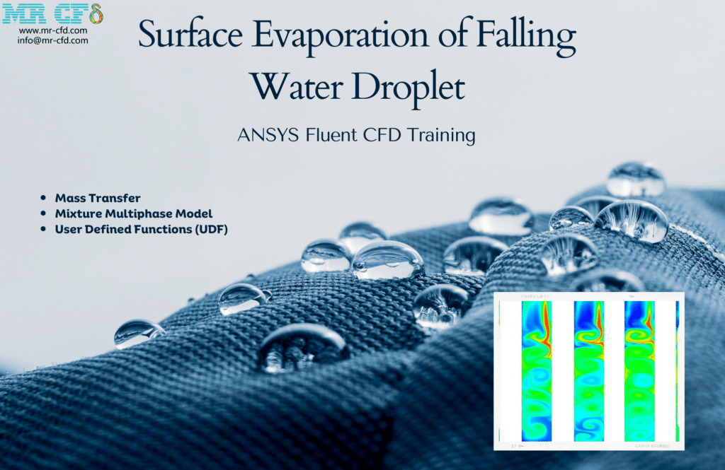
Using ANSYS Fluent software, this simulation explores the surface evaporation of a falling water droplet. We carry out this CFD project and do a CFD analysis to look at it. This Project looks into how water droplet surfaces vaporize into the surrounding air. The simulation’s goal is to learn more about how droplets behave as they fall and how much vapor is released into the atmosphere as a result of water evaporating on the surface of the liquid.
It is thought that it takes 12 seconds to process the downward movement of water within the air space. The drop is unaffected by any external component acting as a boundary condition, and it moves downward only due to the force of gravity. The contours of temperature, velocity, and pressure are obtained after simulation. Air, water, and vapor mass fractions are also obtained as contours. The contours of temperature, velocity, and pressure are obtained after simulation. Air, water, and vapor mass fractions are also obtained as contours. The contours demonstrate that the water droplet is gravitationally traveling downhill. The vapor is produced as a result of the droplets gradually evaporating to the surface after traveling lower.
Condensation inside a Shell and Tube Condenser
The current issue mimics the condensation process inside a shell and tube condenser using ANSYS Fluent software. Condensation is the process by which a fluid changes from a gaseous to a liquid state; as a result, when a liquid vapor reaches its saturation temperature, it becomes a liquid. Latent heat is the heat that results in a phase shift from a liquid to a gas.
The time-frequency coefficient of this mass transfer is defined as 0.1, and the saturation temperature for the condensation process occurrence is given as 46 C. Condensation in this model takes place inside a shell and tube condenser. As a result, cooling water with a flow rate of 5 kg/s and a temperature of 20 C travels through the condenser pipes (tube).
With a flow rate of 10 m/s and a saturation temperature of 46 C inside the shell, water vapor is moving there. Due to contact with the outside of the inner cold pipes, saturated steam undergoes a condensation process, causing its temperature to fall below the saturation temperature. Consequently, liquid water is created.
Two-dimensional and three-dimensional contours relating to pressure, velocity, temperature, water vapor volume fraction, liquid water volume fraction, and the mass transfer rate between water and steam or condensation are acquired after the solution process. The contours demonstrate that the hot steam stream experiences a temperature decrease, which falls below the saturation temperature after coming into touch with the cold-water pipes and heat transfer between the shell and the cold pipes. As a result, the phase change process, water vapor condensation, and water generation in the condenser are all brought about by this process.
Hydrate Formation in Elbow Pipe
The current issue uses the ANSYS Fluent program to simulate the flow of hydrate formation inside a tube with a 90-degree elbow. We carry out this CFD project and do a CFD analysis to look at it. Following the solution procedure, pressure, methane velocity, temperature, and volume fraction for the liquid water phase are produced as two-dimensional and three-dimensional contours. These outcomes were attained throughout a range of simulation process periods (from 0.06 to 0.24 seconds).
As seen in the images, the simulation process advances and a more significant volume proportion of liquid water is created, demonstrating that the condensation process is occurring. As seen in the velocity and pressure contour, the wake region is also visible once the flow crosses the 90-degree bend. A 90-degree pipe causes secondary flows at the output boundary due to the fluid flow.
Eulerian Model
The Eulerian model is one of the most complex models for defining multiphase flows. This model separately solves each phase’s momentum and continuity equations. In contrast, in the Mixture and VOF methods, only the equations for the primary phase are solved (the equations are not solved for the initial phase). The basis of this model is that the Navier-Stokes equations were considered separately for each phase. Applications for the Eulerian model include bubble columns, vertical risers, particle suspension, and fluidized beds.
In computational fluid dynamics (CFD), the Eulerian model is a popular method for simulating fluid flow and transport events. It is based on splitting the computational domain into a fixed grid and solving the fluid’s parameters at each grid point, including velocity, pressure, and concentration.
The Navier-Stokes equations for fluid flow and the advection-diffusion equation for species movement are among the governing equations in the Eulerian model, which treats the fluid as a continuous medium and solves them in a fixed reference frame. The fluid properties are thought to be evenly distributed and homogeneous inside each grid cell, according to the model.
The Eulerian model has the following significant features:
– Grid-Based Approach: The computational domain is discretized into a grid or mesh, with each grid cell standing in for a single tiny volume element. The fluid’s characteristics, including velocity, pressure, and concentration, are solved at each grid point.
– Conservation Equations: The governing equations are solved for each grid cell, including the Navier-Stokes equations for fluid flow and the advection-diffusion equation for species transport. These equations consider the movement of species or other necessary quantities and the conservation of mass, momentum, and energy.
– Turbulence Modeling: Turbulence manifests as a complicated phenomenon in many fluid flow conditions. The effects of turbulence on the flow field can be captured in the Eulerian model using various turbulence models, such as the Reynolds-averaged Navier-Stokes (RANS) equations or large eddy simulation (LES).
– Boundary Conditions: At the edges of the computational area, boundary conditions define the characteristics of the flow. These prerequisites may include predetermined values, velocities, pressure gradients, or other pertinent characteristics. To get accurate and physically plausible results, proper boundary conditions are essential.
– Discretization and Solver: Using numerical techniques like finite difference, finite Volume, or finite element approaches, the governing equations are discretized. Numerical solvers like the SIMPLE algorithm or the conjugate gradient method are then repeatedly used to solve the resulting algebraic equations.
– Postprocessing: After the simulation, the findings can be analyzed and visualized using postprocessing techniques. Creating contour plots, velocity vectors, streamlining patterns, or computing derived quantities of interest, including forces, heat transfer rates, or species concentrations, are a few examples of how this might be done.
Numerous CFD software programs, such as ANSYS Fluent, Open FOAM, and COMSOL Multiphysics, support the Eulerian model. It is a flexible and effective tool for modeling various fluid flow and transport phenomena in various fields, including aerospace, automotive, energy, and environmental engineering.
Population Balance Model (PBM) for Nucleation
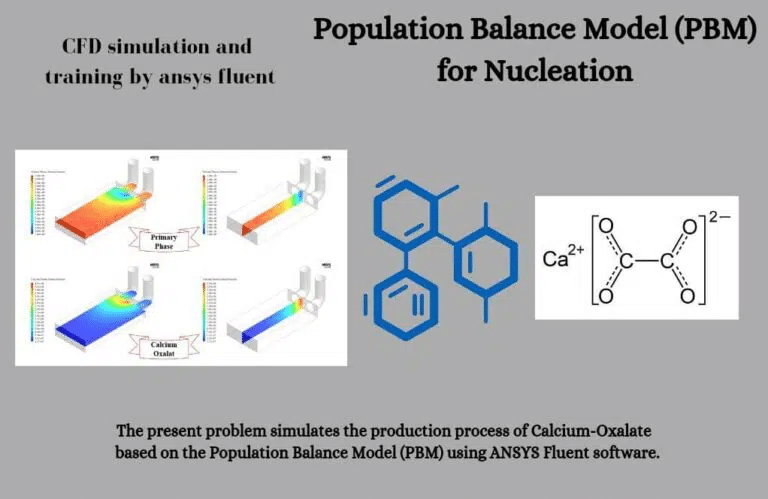
A two-dimensional contour is formed concerning the volume fraction of the primary phase, which includes water, calcium, and oxalate, and the second phase (calcium-oxalate). These contours demonstrate that a chemical reaction and mass transfer from the primary to the secondary phase are responsible for the formation of calcium oxalate. The initial chamber region, the intersection of two intake pipes, is where the desired material is formed.
The table listing the dimensions of each definition category (bin) is then displayed. There are 48 categories for particle size classification, with bin-47 having a minimum size of 5e-7m and bin-0 having the largest size. Additionally, we use the bin number to show the number density bar graph.
The number density shows how many particles there are per unit volume or how many particles fit into the appropriate area, given the size of each bin. A two-dimensional contour of the volume fraction of calcium-oxalate produced in various bins is what we finally get. The findings indicate that the amount of material produced increases starting about bin-30. This indicates that the number of particles created in the bin-0 to bin-30 categories is negligible. The generated particles are formed and grow in smaller volumetric sizes (between bin-47 and bin-30) and are therefore undetectable in larger volumetric sizes, we can infer.
The current issue uses the ANSYS Fluent software to simulate the movement of water vapor through a demister containing saline water particles. Based on data from the reference article “Eulerian-Lagrangian modeling and computational fluid dynamics simulation of wire mesh demisters in MSF plants,” this simulation was created. They are comparing and validating their findings with those in the article. The multistage flash (MSF) desalination system is connected to this demister. The metal wire mesh used in this demister separates the saltwater droplets from the water vapor stream. Consequently, a multiphase flow model must be defined to define the flow in this modeling.
In the current simulation, the dense discrete phase model (DDPM) and the Eulerian multiphase model are coupled using the Eulerian-Lagrangian perspective of computational fluid dynamics (CFD). Thus, a continuous phase related to water vapor and a discrete phase related to salt water droplets is defined. Water vapor and little salt water droplets enter the system from the bottom and exit the top after passing through the metal wire mesh. This research aims to determine how much pressure is lost due to the flow passing through these wire meshes.
The figure in Figure 6 of the literature above is the foundation for validating the current work. The pressure drops between the bottom and top of the demister vary according to the incoming steam velocity, as seen in the graph below. The situation in this diagram involves metal wires that are 0.24 mm in diameter. Each inlet steam velocity value’s pressure drop is measured, verified, and compared to the findings in the article.
Two-dimensional contours relating to temperature, velocity, and volume percent of each continuous (water vapor) and discrete (saline water droplets) phase are obtained after the solution procedure. These contours represent a condition with an incoming steam velocity of 2 m.s-1. As observed in the images, the quantity of distinct saline water droplets dissolved in the steam reduces as the steam rises.
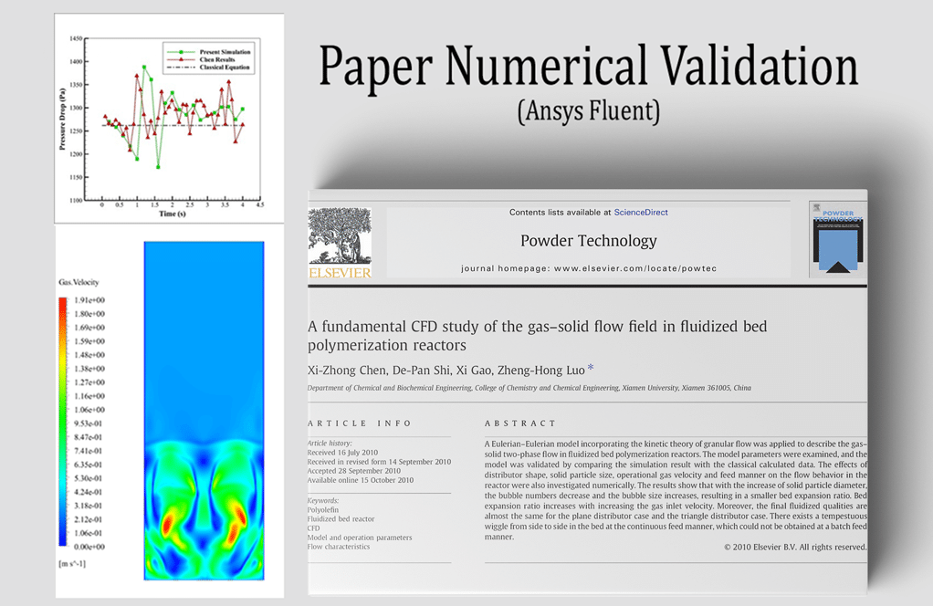
A fundamental CFD study of the gas-solid flow field in fluidized bed polymerization reactors
Using the ANSYS Fluent software, a fluidized bed polymerization reactor is simulated. We carry out this CFD project and do a CFD analysis to look at it. Using catalysts, a reactor is a device that performs chemical reactions (conversion, composition, decomposition, etc.), transforming raw materials into desired products.
Reactors must be designed with higher efficiency but lower cost and energy consumption due to the economics of their production; as a result, factors like Volume, temperature, pressure, particle concentration, particle residence time, heat transfer coefficient, and reaction rate are crucial when designing reactors.
Chemical reactors can be categorized in various ways: homogeneous, heterogeneous, pipe and tank reactors, fixed and fluidized bed reactors, and continuous and discontinuous reactors. In fixed bed reactors, the solids operate as a catalyst by remaining stationary inside the reactor as the reactants move across them, reacting and ejecting the reactor. Solids are reactants or catalysts suspended in the flow under pressure in these fluidized bed reactors.
There are benefits to using a fluidized bed reactor, such as high heat and mass transfer rates, a smaller heat transfer surface, consistent temperature distribution, proper temperature control, and complete and quick mixing of reactors and catalysts. The capacity to manage temperature and prevent the production of hot spots, which is essential for any reaction, is the fundamental benefit of the fluidized bed-type reactor over the fixed bed type. Numerous industrial uses for fluidized bed reactors exist, including petrochemical, chemical, electricity generation, incineration, etc. With straightforward geometry, this issue will imitate a two-phase flow inside a fluidized bed reactor.

Following the simulation, two-dimensional contours for the pressure of the mixture, the velocity of the gas flow and the suspended solids, and the volume percent of the gas flow and solid suspended particles from 0 to 4 seconds are obtained. Additionally, the value of the pressure at the entrance and outflow is measured. Since the pressure drop is equal to the static pressure differential between the inlet, the pressure drop in the model has thus been derived at various times.
As a result, the pressure decrease is shown as a function of time. The facet average was used to calculate the pressure drop over time (every 0.2 seconds), and the results from the article were compared. The article’s illustration in Figure 6 was utilized to validate the results of the current numerical simulation. This graph displays the model’s internal pressure decline over 4 seconds. The numerical simulation findings of the present with those of the numerical work of the article are compared.
Reverse osmosis CFD Simulation using ANSYS Fluent software is the subject of this simulation. Fluid tends to migrate from a solution with a lower concentration to a greater concentration until the concentration on both sides is balanced, as demonstrated by the natural phenomenon known as osmosis. Imagine a semipermeable membrane separating that pure and impure water.
When a pressure differential between the two pure and impure sections (on both sides of the membrane) first arises, water movement, according to the osmosis phenomena, is in the direction of impurity. The osmotic pressure difference is the name given to this pressure variation. This fluid transfer from the pure to the impure parts of the system is stopped if a pressure corresponding to the osmotic pressure is applied to the non-specific component. The direction of water’s natural flow is reversed if this pressure is higher than the osmotic pressure.
Water desalination systems using reverse osmosis operate precisely following this process. These devices reversely apply pressure toward the semipermeable membranes higher than the osmotic pressure. Salt and other contaminants are separated from base water by passing through filters.
This Project has undergone two simulations and has two difficulties. In the first Project, osmotic pressure-related fluid behavior is the only topic covered and modeled in a closed chamber split into two sections. It is intended to remove a barrier between these two sections simultaneously.
A saltwater solution is on the left side of the chamber, and the right is pure water. This simulation aims to examine the flow of fluid between two regions with various concentrations. This displacement can convey the ideas of osmotic pressure and the osmotic phenomenon.
If the first Project is authorized, the reverse osmosis water desalination technology will be researched in the second Project. In this simulation, the system chamber’s center is covered by a membrane. A porous medium has defined the membrane. Water and salt travel toward the membrane as they enter the chamber through the intake on the model’s left side. Pure water travels through the membrane once the solution approaches and contacts it, whereas salty or highly concentrated water is retained behind it.
Two-dimensional contours relating to the pressure and volume percentage of water and salt have been produced when the solution process is complete. The results have been compared at various intervals to acquire the system’s behavior over time because the solution is unstable. An animation showing how the volume percentage of salt soluble in water changes has also been obtained. Both simulation modes yield the same results in every case.
The system is not subjected to any external boundary constraints in the first simulation, which has a closed enclosure. The model’s left side initially has water and salt, while the right side solely has pure water. The fluid is observed to flow from the side with a greater concentration to the side with a lower concentration over time, according to the data.
This displacement continues until equilibrium is reached for the concentration on both sides of the system. Without the help of outside forces, this fluid motion occurs naturally. This occurrence demonstrates the fluid’s osmotic characteristic, accurately described in the issue.
The second simulation fills the system’s middle with a porous membrane or medium. Beyond the osmotic pressure, the water and salt solution travels toward the membrane at a certain speed and pressure. According to osmotic pressure, this movement goes against how fluids typically travel.
The findings demonstrate that while clean water can travel through the membrane, salt dissolved in the water cannot because it is retained behind the membrane. This motion continues until pure water is acquired after the membrane and an entirely concentrated solution is obtained behind the membrane. These outcomes demonstrate the effectiveness of the reverse osmosis sweetening system and the efficiency of the water filtration procedure. The fluid pressure difference on both sides of the reverse osmosis system also grows over time by pressure changes.
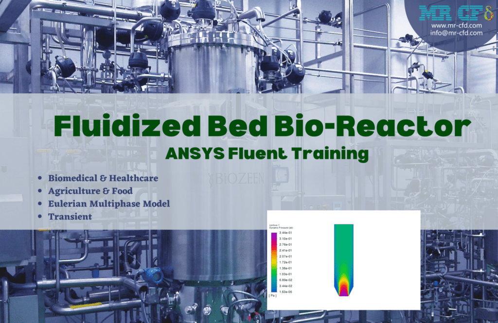
The fluidized bed bio-reactor is being studied in this study. Multiple multiphase chemical processes can occur in a fluidized bed bioreactor (FBR). A fluid (gas or liquid) is fed through a solid granular material (often a catalyst) in these reactors at a high rate to suspend the solid and make it behave like a fluid. The third chapter of the Eulerian Multiphase Model Training Course is contained in this package. The fluidization process affords FBR several significant benefits. FBRs are therefore utilized in various industrial applications, including the biomedical and food industries.
Finally, as the results demonstrate, the silicon particles tend to move upward due to the air blowing underneath them since the force applied to the silicon particles balances their weight. The temperature of the fluid also varies, much like in a genuine bioreactor. Given that catalysts function best at higher temperatures, this temperature change aids in the acceleration of the processes.
The saturated water pool boiling inside a cylindrical chamber is the subject of this research. Pool boiling is the term used to describe the boiling of a heated surface submerged in a sizable amount of still liquid. Saturated pool boiling is used when the liquid is at its boiling point. Subcooled pool boiling is used when the liquid is below its boiling point. The second chapter of the Eulerian Multiphase Model Training Course is contained in this package.
In academic experimental applications where circumstances like ONB (Onset of Nucleate Boiling), DNB (Departure from Nucleate Boiling), and CHF (Critical Heat Flux) are explored, the motion of the liquid caused by the boiling process and the velocities are supposed to be modest. In industrial equipment and applications, where extreme circumstances like burnout may occur, pool boiling is uncommon.
The results of the process of boiling are then obtained and displayed. Vapor tends to travel upward, as shown by the volume fraction contour for the vapor phase. As a result of this motion, the water experiences convective motion that results in many nucleation sites. Furthermore, the evolution of the bubbles’ morphologies may be observed. Additionally, when they go upward in the outflow direction, it is clear how they exchange mass with the nearby water (condensation).
Wet Steam Model
A thermodynamic model called the “wet steam model” explains the characteristics and behavior of steam that comprises a mixture of liquid and vapor. It is frequently utilized in engineering settings where steam is a working fluid, like power plants.
The quality or dryness fraction, which denotes the proportion of the mass of vapor to the total mass of the mixture, is used in the wet steam model to calculate the attributes of the steam mixture. Pure liquid water has a quality of 0, while pure dry vapor has a quality of 1.
The wet steam model has the following essential features:
– Saturation Curve: A saturation curve in the wet steam model often represents the boundary separating the liquid and vapor phases of steam. The relationship between temperature and pressure at which steam is in equilibrium between the two phases is depicted by this curve.
– Enthalpy and Entropy: The wet steam model considers the enthalpy and entropy of the steam combination. The mixture’s total energy content, including sensible heat and latent heat, is represented by enthalpy. Entropy is a measurement of the system’s disorder or randomness.
– Phase Change: The wet steam model accounts for the phase change processes when the steam combination condenses or evaporates. Latent heat transfer, which alters the mixture’s temperature and enthalpy, is included in this.
– Property Calculations: The wet steam model offers equations to compute the particular Volume, specific enthalpy, specific entropy, and specific internal energy of the steam mixture. These characteristics are frequently described as quality, pressure, and temperature functions.
– Steam Tables: To provide tabulated values of steam properties in various situations, steam tables are frequently used with the wet steam model. These tables contain temperature, pressure, Volume, enthalpy, entropy, quality, and specific Volume data.
– Transitions Between Different Steam Quality States: The wet steam model supports changes in the steam quality from wet to dry or vice versa. To precisely simulate the behavior of the steam, these transitions, which can take place during procedures like throttling, expansion, or condensation, are crucial.
It’s essential to remember that there are various wet steam model versions, each with its own presumptions and mathematical formulas. Depending on the application and the needed level of precision, a particular model may be employed. The wet steam model, in general, is a helpful tool for engineers and researchers to assess and build steam-based systems, assuring effective and secure operation in various industries, including power generation, chemical processing, and thermal systems.
Wet Steam for Condensation inside a Steam Ejector
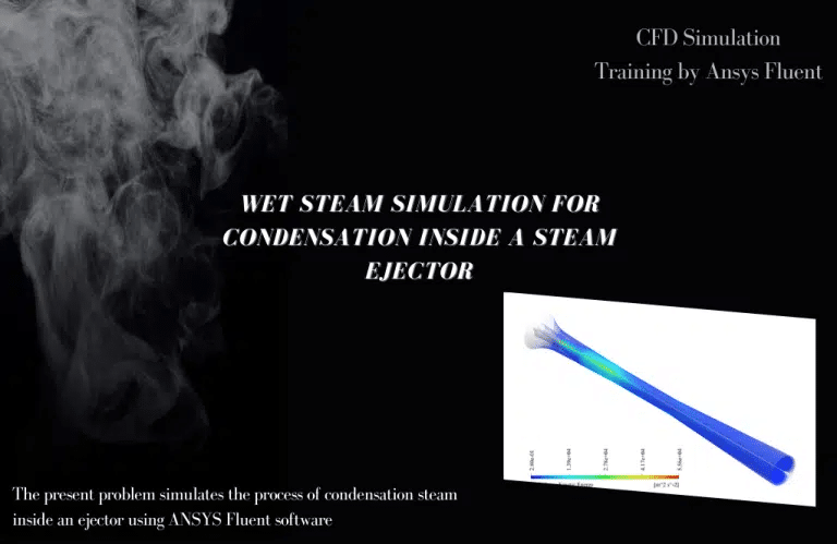
The suction substance, the two actuator fluids, and the mixture are removed from the system. Ejectors have two primary uses: vacuuming and sucking gases and mixing fluids. According to the continuity equation, the ejector structure takes the shape of a convergent-divergent tube that receives the driving fluid and passes through the nozzle’s converging part, increasing the velocity of the passing fluid by decreasing its cross-sectional area. In other words, the fluid’s potential energy is transformed into kinetic energy.
Following Bernoulli’s law, the fluid pressure then falls with increasing velocity, which predicts that the fluid’s kinetic energy will do the same. The secondary material is drawn into the ejector due to the pressure decrease, creating a compressive vacuum inside the ejector. The primary stimulation fluid and the suction secondary material are combined and squeezed in the diffuser section.
After the solution process, we acquire two-dimensional contours corresponding to pressure, velocity, temperature, turbulent kinetic energy, and the mass production rate of liquid vapor (the same as the density rate). By rotating this two-dimensional contour around the central axis, generating a three-dimensional contour of the same values is also feasible. One of the most significant conclusions that may be examined is the pace at which liquid mass is generated.
Multiphase Flow Application in Industrial Companies
Simulations of multiphase flows are used in various industrial settings and industries. Here are a few instances:
– Oil and Gas Industry: Multiphase flow simulations are widely used for reservoir modeling, wellbore design, and production optimization in the oil and gas sector. They aid in estimating production rates, improving the extraction procedure, and comprehending the behavior of water, gas, and oil flows in subterranean reservoirs.
– Chemical and Process Engineering: Multiphase flow simulations are used in the chemical and process engineering industry to research mixing and reaction processes, construct and improve reactors, and examine the behavior of multiphase systems such as gas-liquid or gas-solid flows. These simulations help increase process effectiveness, lower costs, and guarantee safe operation.
– Power Generation: In the power generation sector, including nuclear and thermal power plants, multiphase flow simulations examine coolant flow, condensation processes, and steam dynamics. These models aid in predicting pressure drop, optimizing heat exchanger design, and improving the overall power production system efficiency.
– Pharmaceutical and Biotechnology: Multiphase flow simulations are used in the pharmaceutical and biotechnology industries to research fluid mixing, mass transfer, and reaction kinetics in bioreactors and other process machinery. They help to ensure product quality and process scalability by optimizing the manufacturing of medicines, vaccines, and biofuels.
– Food and Beverage Industry: Multiphase flow simulations are used in this sector to analyze fluid dynamics, heat transfer, and mixing processes in various processing equipment, such as mixers, heat exchangers, and spray dryers. These simulations help with process optimization, product quality enhancement, and food safety assurance.
– Automotive and Aerospace: To investigate fuel injection, combustion processes, and aerodynamics in these industries, multiphase flow models are used. They aid in enhancing the design of aerodynamic parts like wings and airfoils and improving engine performance while lowering emissions.
– Mining and Minerals Processing: In mining and minerals processing, multiphase flow simulations examine slurry flows, sedimentation, and particle transport in pipelines and mineral processing machinery. These simulations assist in maximizing the recovery of essential minerals, avoiding losses, and optimizing the design and operation of mineral processing plants.
These are only a few instances of industrial enterprises using multiphase flow simulations. The specific uses and advantages differ according to the methods used and the sector. Multiphase flow simulations offer helpful insights into the behavior of complicated fluids, enabling businesses to increase productivity, optimize designs, cut costs, and guarantee secure operation.
MR CFD Industrial Experience in the Multiphase Flow Field
Some examples of Multiphase Flow industrial projects recently simulated and analyzed by MR CFD in cooperation with related companies are as follows:
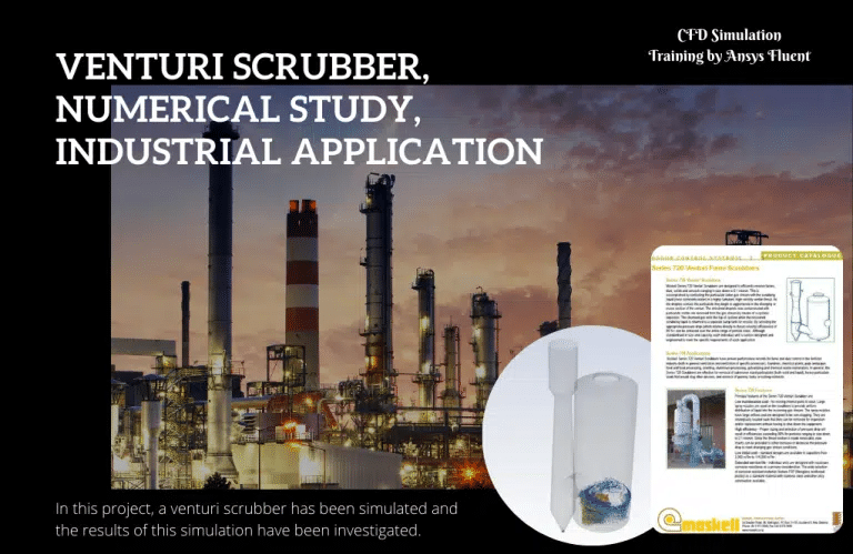
The sector faces a sizable issue with separating particles from the gas flow. A Venturi scrubber that eliminates gas particles is one of the most excellent methods for overcoming this problem. Additionally, it is more effective than other scrubbers (such as wet and cyclone scrubbers). The purpose of venturi scrubbers is to collect and remove particles with high efficiency (above 99%). Venturi is widely employed to remove various particles in numerous sectors due to their high capabilities when the Volume of incoming gas and its temperature are high.
When the incoming gas is heated to more than 350 c, this capacity is especially desired to reduce cement kiln emissions and regulate simple oxygen kiln emissions in the steel industry. The emission of fly ash from cement and sulfur dioxide furnaces in industrial and boiler boilers is also controlled by ventures.
High liquid-to-gas ratio, liquid atomization, and open structure allow for the efficient, low-maintenance purification of severely polluted gases with infinite flow reversibility. Venturi is one of the most adaptable systems because it can simultaneously eliminate hazardous gases and particles under various circumstances. This scrubber is employed in various sectors since Venturi is typically used in the initial stage of multistage systems to manage gas or air flow pollution.
This research stimulated an industrial Venturi scrubber using ANSYS Fluent software. Venturi scrubbers collect up to 0.1 micrometer-sized particles and gas pollutants. Despite having a large amount of water inside, the device increases the number of particles and toxins that water contacts.
As a result, the scrubber traps the particles and removes them from the fluid. The current Venturi Scrubber was simulated, and it was found that this device has the efficiency needed for industrial applications. The Venturi scrubber atomizes the gas flow scrubber using the energy from the intake gas.
The convergent, the throat, and the divergent make up the Venturi scrubber. As the area shrinks, the gas flow rate increases as it enters the convergent region. The system also receives a fluid addition at the converging part’s throat or intake. High-speed gas entering the system travels via the throat, where the liquid is added, and many droplets are created.
The throat is where impurities and particulates are removed from the gas stream. It happens when tiny liquid droplets and the oncoming gas stream collide. After that, the incoming gas travels in that direction. It is the location where the flow will escape slowly and drown in water.
Venturi scrubber benefits:
- Reduced maintenance costs and little area requirements.
- Management of corrosive, flammable, or explosive contaminants and cooling of heated gases.
Venturi scrubber disadvantages:
- high-pressure loss
- needs much electricity
The device is simulated accurately because it is shown that when the pressure in the Venturi lowers, velocity and turbulence increase, and water and particle disturbances work better. This Project simulates a Venturi 720 series scrubber in size 720-2. However, supposing we wanted to employ a Venturi scrubber in a different industry (with a different gas flow or particle flow). This simulation size allows for faster attainment of the ideal condition for the targeted industry.
According to the supplied data, the planned water nozzles and flow characteristics could contain sand particles. Only 0.02% of the injected particles could escape, demonstrating astounding efficiency. It can therefore be deployed without hesitation on the industrial trunk line for which it is intended.
This Project discusses a well-known impact turbine. The only impact hydraulic turbine in operation right now is the Pelton turbine. The energy produced by this turbine is produced by a fluid jet following Newton’s second law. This turbine rotates the runner by being struck by a pressure water nozzle tangentially to the bucket attached to the runner.

In this Project, ANSYS Fluent software is used to simulate a tiny Pelton turbine with a diameter of 300 mm and 15 buckets. This experiment also tries to measure the torque generated by the turbine. At age 30, American inventor Lester Allen Pelton visited the American West to pursue gold and worked at a mine in northern California. Most tasks were completed at that time using steam engine power. However, the fuel for these engines was much wood.
Small rivers near the mine lacked the need for the inefficient water cycles employed in huge rivers. Pelton, therefore, started to develop a wheel that could function at low water flow rates. He constructed his first lab turbine out of wood in the middle of the 1870s, and the first actual sample of iron was installed at a mine close to Nevada in 1878. The Pelton wheel quickly began mass production thanks to its advantageous features and efficiency.
Pelton took the effort to create a separator that would split the input jet into two equally sized streams. The efficiency of the water cycle was raised using the same concept from 35% to 90%. Impact turbines can be of various types. However, Pelton’s model is still the most effective.
Nozzles are arranged so one can direct and tangentially fling its water jet toward the center of each plate and the disk. The input jet is separated into two equal streams by a separator or splitter before entering each plate. Following going through a curved path on the inside of the plate in the opposite direction of the input jet, these two equal streams exit the plate. This Project aims to determine Pelton’s produced momentum and lateral force to choose the best axis.
You may find the Learning Products in the Multiphase Flow CFD simulation category in Training Shop. You can also benefit from:
Volume Of Fluid (VOF) Model
- VOF Multiphase Flow Training Package, which is appropriate for Beginners (part 1 & part 2), Intermediate (part 1 & part 2), Advanced (part 1 & part 2), and Expert users of ANSYS Fluent.
- VOF Multiphase Flow Model Training Course
Mixture Model
- The mixture Multiphase Flow Training Package is appropriate for Beginner, Intermediate, Advanced, and Expert users of ANSYS Fluent.
- Mixture Multiphase Flow Model Training Course
Eulerian Model
- Eulerian Multiphase Flow Training Package is appropriate for Beginner, Intermediate, and Advanced users of ANSYS Fluent.
- Eulerian Multiphase Flow Model Training Course
Also, MR CFD is presenting the most comprehensive Multiphase Flow Training Course for all ANSYS Fluent users from Beginner to Experts.
Our services are not limited to the mentioned subjects. The MR CFD is ready to undertake different and challenging projects in the Combustion modeling field ordered by our customers. We even carry out CFD simulations for any abstract or concept Design you have to turn them into reality and even help you reach the best strategy for what you may have imagined. You can benefit from MR CFD expert Consultation for free and then Outsource your Industrial and Academic CFD project to be simulated and trained.
By outsourcing your Project to MR CFD as a CFD simulation consultant, you will not only receive the related Project’s resource files (Geometry, Mesh, Case & Data, …), but also you will be provided with an extensive tutorial video demonstrating how you can create the geometry, mesh, and define the needed settings (preprocessing, processing, and postprocessing) in the ANSYS Fluent software. Additionally, post-technical support is available to clarify issues and ambiguities.
