CFD Project Outsourcing
Outsource your CFD project to the MR CFD simulation engineering team. Our experts are ready to carry out every CFD project in all related engineering fields. Our services include industrial and academic purposes, considering the ANSYS Fluent software's wide range of CFD simulations. By outsourcing your project, you can benefit from MR CFD's primary services, including CFD Consultant, CFD Training, and CFD Simulation.
The project freelancing procedure is as follows:
An official contract will be set based on your project description and details.
As we start your project, you will have access to our Portal to track its progress.
You will receive the project's resource files after you confirm the final report.
Finally, you will receive a comprehensive training video and technical support.
What is Radiation?
Radiant heat, also known as thermal radiation, is the transfer of electromagnetic radiation, which describes photons’ heat exchange of energy. Radiant heat is a mechanism for heat transfer that does not require a medium in which it propagates (unlike convection and conduction). All substances above absolute zero have thermal energy, meaning their particles have some form of motion. This motion of the particles contributes to the object’s temperature, with objects of “ordinary” temperatures (less than 1000 Kelvin) emitting their radiant heat primarily in the infrared spectrum of light. The photons emitted by these moving charged particles will travel at the speed of light until they hit another particle, which absorbs its energy as kinetic energy. Interacting systems at different temperatures will exchange radiant heat until they reach thermal equilibrium.
Radiation is energy emission through electromagnetic waves or subatomic particles in motion, particularly high-energy particles that induce ionization. Along with conduction and convection, it is a fundamental energy transfer mechanism. Radiation can be divided into two categories: ionizing and nonionizing.
Nonionizing Radiation: This radiation has less energy and cannot ionize (remove electrons from tightly bound atoms) particles. Radio waves, microwaves, infrared radiation, and visible light are examples.
Ionizing Radiation: This radiation has sufficient energy to unbind electrons from atoms, producing ions. Radiation examples include X-rays, gamma radiation, and radioactive decay particles such as alpha and beta particles.
Thermal radiation in the context of heat transfer is electromagnetic radiation produced by the thermal motion of particles in matter. All substances with temperatures above absolute zero produce thermal radiation. Radiation is crucial in numerous scientific and technological processes, such as medical imaging, cancer treatment, energy generation, and communication systems. The Stefan-Boltzmann radiation law can explain the theory behind the heat transfer rate by emitted radiation.
Where σ = 5.67 × 10⁻⁸ J/s · m2 · K4 is the Stefan-Boltzmann constant, A is the surface area of the object, T2 and T1 are the absolute temperatures of the first and second systems in kelvin. The symbol ε stands for the object’s emissivity, which measures how well it radiates. An ideal jet-black (or black body) radiator has ε = 1, whereas a perfect reflector has ε = 0. Real objects fall between these two values. For example, tungsten light bulb filaments have an ε of about 0.5, and carbon black (a material used in printer toner) has the (greatest known) emissivity of about 0.99.
How can Radiation CFD simulation be applied in Engineering and Industries?
Simulations of radiation Computational Fluid Dynamics (CFD) play a crucial role in a vast array of engineering and industrial applications. It enables engineers to predict and analyze radiation heat transfer in various systems, enhancing system design and performance. Here are a few examples of applications:
- Energy Sector
Radiation CFD simulation is utilized in designing and analyzing combustion systems in the energy industry, such as boilers and furnaces. It aids in comprehending radiation heat transmission within these systems, optimizing their Design for increased efficiency and decreased emissions.
Radiation CFD simulation is utilized in the automotive industry to design radiators and exhaust systems. It aids in comprehending how heat is radiated from these components and how this impacts the thermal management of the vehicle as a whole.
- The Aerospace Sector
Spacecraft and satellites are designed using radiation CFD simulation in the aerospace industry. It aids in comprehending radiation heat transfer in space, which is essential for spacecraft thermal management.
- Electronics Business
Radiation CFD simulation is utilized in the thermal management of electronic devices and systems in the electronics industry. It aids in comprehending how heat is radiated from electronic components and how this affects the device’s overall thermal performance.
- Construction and Building Industry
Radiation CFD simulation is utilized in the building and construction industry to design energy-efficient structures. Understanding how heat is radiated inside and outside the building is essential for the thermal comfort of the occupants and energy efficiency.
- The Health Care Industry
Radiation CFD simulation is utilized in the medical industry to design and analyze medical devices and procedures involving radiation, such as radiation therapy for cancer treatment.
Overall, radiation CFD simulation is a potent instrument that facilitates the comprehension and prediction of radiation heat transfer in various systems, optimizing Design and enhancing performance.
MR CFD services in the Radiation Simulation for Engineering and Industries
With several years of experience simulating various problems in various CFD fields using ANSYS Fluent software, the MR CFD team is ready to offer extensive modeling, meshing, and simulation services. Simulation Services for Radiation CFD simulations are categorized as follows:
- Solar Radiation at Different Hours
- Solar Shading Double Glazing façade
- Radiation Heat Transfer, Computer Room
- Radiation Heat Transfer in Combustion Chamber
- Solar Radiation Effect on a Gasoline Tank
- Finding outlet temperature in Solar collectors in various flow rates and shapes
- Using phase change material (PCM) for storing energy in a solar water heater
- …
MR CFD is an industry leader in Computational Fluid Dynamics (CFD) services, such as radiation simulation. Their services are utilized in various engineering and industrial fields to optimize performance and guarantee efficiency. Here are some ways in which MR CFD can aid in radiation simulation:
Personalized Simulation Solutions
MR CFD offers radiation simulation solutions tailored to each Project’s specific requirements. We can simulate various radiation scenarios, including nonionizing and ionizing radiation in various mediums and conditions.
Advanced Simulation Instruments
MR CFD employs advanced CFD software tools for radiation simulations, such as ANSYS Fluent and OpenFOAM. These instruments enable precise and comprehensive radiation heat transfer analysis, allowing engineers to make informed design decisions.
Expertise in Multiple Industries
MR CFD can provide industry-specific radiation simulation solutions due to its expertise in numerous industries, such as energy, automotive, aerospace, electronics, building and construction, and medical. We comprehend each industry’s challenges and requirements, ensuring that simulation results are applicable and actionable.
Exhaustive Reports
MR CFD generates comprehensive reports on the results of radiation simulations, including analysis and recommendations. These reports can assist engineers in comprehending their system’s radiation behavior and making the necessary adjustments to enhance performance and safety.
Instruction and Support
In addition to providing radiation simulation services, MR CFD provides CFD and radiation simulation training and support. In the future, this can help engineers and researchers develop their capabilities in these areas and undertake their simulations.
In conclusion, the radiation simulation services offered by MR CFD can provide invaluable insights and solutions for various engineering and industrial applications. Their knowledge and cutting-edge instruments can aid in optimizing system design, enhancing performance, and ensuring safety and efficacy.
Solar Devices
Solar Device CFD Simulation Training Package
The Solar Device CFD Simulation Training Package consists of seven distinct CFD simulation projects utilizing the ANSYS Fluent software and various Solar Devices. MR-CFD recommends this program to anyone interested in Renewable Energy Engineering, specifically Solar Energy analysis. This package introduces you to multiple project descriptions and designs and how to simulate them, considering a vast array of numerically relevant studies.
To validate our CFD methodology, we begin the training program with a paper validation concerning the Effects of geometric parameters on the performance of solar chimney power plants. Then, we continue the program by investigating a three-dimensional solar chimney and solar chimney applications for Solar Air Conditioning (HVAC). Then, a solar heat exchanger and a solar-powered radiator are investigated. Lastly, two simulations are conducted with PCM application to a solar collector and solar water tank heater.
You can claim to be an expert in modeling and analyzing every solar device and application-related CFD simulation after completing this fantastic and practical training package. Then you will be qualified to work as a CFD engineer in the relevant industries.
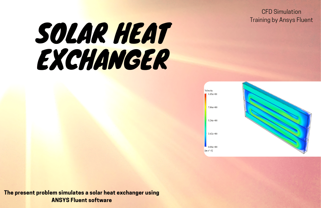
The water flow is introduced into the heat exchanger with an initial velocity of 4 m/s and a temperature of 30 °C. Subsequently, it exits the heat exchanger under atmospheric pressure. The absorber wall of the heat exchanger is subjected to solar radiation and acquires thermal energy via radiant heat transfer.
As the sun’s heat intensifies, the temperature of the air gap in front of the absorber plate increases. The rise in atmospheric temperature leads to heat transmission to the absorber plate, facilitating heat transfer from the absorber plate to the water flow within the heat exchanger.
Consequently, the water flow rate within the system exhibits an upward trend in response to the temperature received by the absorber plate. The heat exchanger incorporates many rows of inner walls that function as a barrier to augment heat transfer. This design feature extends the water flow path and boosts the likelihood of contact with the absorber plate.
Following the simulation’s completion, we obtained two-dimensional (2D) and three-dimensional (3D) contours that pertain to the variables of pressure, velocity, and temperature. The findings indicate a progressive rise in the water flow temperature as it moves from the intake part to the output area. The observed temperature variations suggest that radiative heat transfer and the impact of sun ray tracing are fully utilized in the heat exchanger absorber plate, affecting the water flow.
How to Model Radiation inside ANSYS Fluent
The radiation energy model is generally divided into two categories of radiation between different surfaces (including P1, S2S, DTRM, DO, and MC methods) and Solar-Ray Tracing. The Solar Calculator section defines the geographic region’s Latitude and Longitude, Time Zones, Hours, and Days of radiation. In the Sun Direction Factor section, the direction of the solar radiation can be determined. Direct Solar Irradiation is also considered (W.m-2). In addition, by enabling the Use Direction Computed from The Solar Calculator option, the direction of solar radiation to the model would be defined based on the input data to the Solar Calculator.
Other radiation heat transfer models are also available in ANSYS Fluent software, including:
- DO
- DRTM
- P1
- S2S
- Roseland
- Monte Carlo
- Solar Ray Tracing
In general, to select the best model of radiation heat transfer, the following is done:
- From a computational cost point of view:
P1 is reasonably accurate but low effort.
- From the point of view of solution accuracy:
DO, and DTRM are more accurate.
- Optical Thickness point of view:
DTRM and DO are Suitable for Thin Optical Thickness (𝛂L “1), and P1 is Suitable for Thick Optical Thickness.
- In terms of dispersion or diffusion:
P1 and DO are suitable for diffusion.
- In terms of particle effects:
P1 and DO suit the radiation exchange between gas and fine particles.
- From the viewpoint of local heat sources:
DO and DRTM are good enough with high radiation.
Discrete Ordinates Model (DO)
The discrete ordinates model (DO) is used for cases where the radiative heat transfer equations are solved for a discrete number of solid finite angles. Its advantages are that it is the most comprehensive radiation model, and the solution accuracy is enhanced by better discretization. This stable method results in a thermal energy balance for coarse discretization. It uses for light scattering, semitransparent environments, glossy sheets such as mirrors, and wavelength-dependent transmission using the gray background while resolving it with a wide variety of angles is heavy for the CPU, as a limitation of this model.
The current problem simulates heat transfer in a room through a radiant underfloor heating system using ANSYS Fluent software. We perform this CFD endeavor and analyze it using CFD simulations. This simulation is based on an article entitled “Numerical study on the influence of non-heating surface temperature on the heat output of radiant floor heating systems.” The CFD simulation results are validated by comparing them to the paper results.
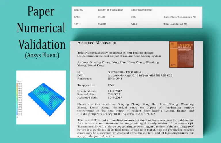
On this two-dimensional plate, a temperature contour in two dimensions is obtained. These contours will indicate when heat transfer occurs. The resulting contours indicate that heat is transferred from the outer surface of the conduit to the interior of the room, resulting in heating of the air within the room. The simulation is validated using Tables 5 and 6 from the cited article.
The outlet temperature of the conduit is derived from Case 1 of Table 5 of the article. Using the area-weighted average at the outlet boundary of the conduit, it is compared to the temperature value calculated during this simulation. In addition, the surface heat output power is extracted from Case 1 of Table 6 of the article. The total heat transfer rate on the outer surface of the conduit is compared to the heat transfer rate calculated by this simulation.
This Project is the ANSYS Fluent-based CFD combustion simulation in a bluff-body mild burner. In reality, a burner is a device that combines a certain quantity of air with fuel in a safe space, converting fuel energy into heat energy and producing some gas in the process of combustion. Using convection and radiation, the flame generated by the burner is transmitted to the interior of the chamber. Consequently, the Radiation (DO) model should be incorporated into the current model. In addition, since combustion occurs within the combustion chamber, the Species Transport model is also utilized.
The fuel is sprayed through a special jet inlet into the chamber of this burner, and the gas flows symmetrically into the chamber from four directions, combining the fuel and air to create the flame. In addition, the enclosure’s operating system also features a cyclical gas flow path within the chamber, with a portion of the gas exiting the exhaust section and another returning to the enclosure via the same circular path.
Discrete Transfer Radiation Model (DTRM)
The discrete transfer radiation model (DTRM) is used for cases where the radiation emitted from a surface element in continuous and specified intervals of solid angles can be considered a single ray. Its advantages are that the model is relatively simple, capable of increasing accuracy with the increasing number of rays, and can be applied to a wide range of optical thicknesses, while limitations are that not all pages are scattered, the effects of radiation scattering are not taken into account, and the solution is very heavy for the CPU.
This Project entails a numerical simulation of natural ventilation within an atrium building, explicitly focusing on the radiation heat transfer mechanism known as Discrete Transfer Radiation Model (DTRM). The ANSYS Fluent program will be utilized for this purpose. The current Project’s model pertains to the inner area of a straightforward atrium building featuring three levels of rooms on two opposing sides. Each room on different stories has an airflow inlet in the lower half. Moreover, a panel is designated to facilitate air departures on the wall opposite the doors.
The upward movement of outgoing airflow occurs within the central region of the atrium building. Ultimately, the air is discharged from the ultimate outlet panel at the apex of the atrium. The center atrium building and each of its rooms contain a variety of heat sources, such as thermal and electrical equipment, among others. Moreover, the architectural Design of the building incorporates a glass exterior, which is directly exposed to solar radiation.
The transfer of thermal energy can occur through the processes of conduction and convection. Nevertheless, it is postulated that the Project also encompasses radiation heat transfer. This study examines the impact of various heat transfer mechanisms and sun radiation on natural air conditioning.
Following the conclusion, we have acquired the contours of temperature, pressure, velocity, and density. In addition, velocity vectors were also shown. The findings indicate that the room air is warmed using heat sources on each level’s floor.
Nevertheless, the atrium building’s natural ventilation system facilitates air movement from the exit portion of each floor to the central area. Subsequently, the air is expelled from the upper region of the atrium building. This phenomenon facilitates the efficient circulation of airflow throughout the structure. The CFD Project discussed above represents the fourth installment of the Radiation Model Training Course.
P1
The P1 model is used for cases where the independence of direction is integrated into the radiative heat transfer equations and thus results in a diffusion equation for random radiations. Its benefits include that the radiation heat transfer equation can be easily solved with a low CPU, including the effects of light scattering, such as the effects of particles or droplets of water or soot, and work well in applications such as combustion that have high optical thicknesses; while the limitations are that all plates are scattered, they may have low accuracy in some cases, especially in low-thickness geometries, and it is prone to predicting fluxes from local heat sources or sinks.
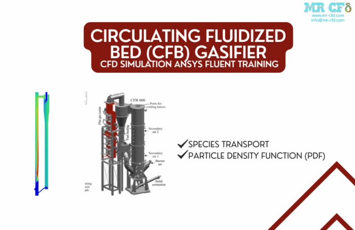
Circulating Fluidized Bed (CFB) Gasifier
Industrial and academic applications of the Circulating Fluidized Bed gasifier are prevalent due to its inherent advantages of high circulating rate, low operating temperature, broad fuel flexibility, and negligible pollutant emissions. A basic CFB cycle has been simulated, and results have been obtained in this simulation.
The system has two inlets, a vertical inlet for oxidizer and a horizontal inlet for fuel; the air and fuel, after being mixed, begin flameless combustion in a vertical section and then enter the cyclone to separate unburned ashes as polluted air, unburned fuel circulates to the bottom of the downstream section. It enters the process again, and heavy sands and ashes exit the bottom outlet. The particle density function (PDF) was used in this simulation to simulate solid dynamics.
The simulation results reveal that the combustion of the fuel-air mixture in the vertical chamber and the cooling of the resulting heated gases in the cyclone and the second chamber are examined, as are the polluting gases of the maximum face. Within the cyclone, unburned materials are separated and reintroduced to the combustion process.
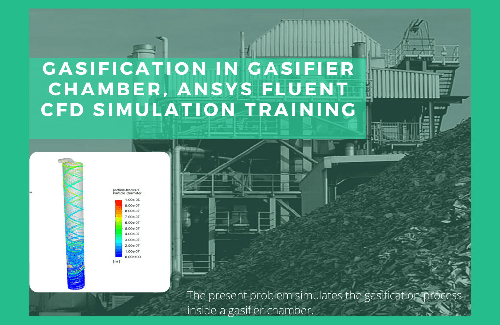
Gasification in Gasifier Chamber
ANSYS Fluent software simulates the gasification process within a gasifier chamber for the current problem. During gasification, chemical reactions convert a carbon-based substance to carbon monoxide, hydrogen, and carbon dioxide. This product is considered a renewable energy source with numerous industrial applications.
In this instance, the term “fuel” refers to a substance with a density of 1550 kg.m-3 and a specific heat capacity of 1680 j.kg-1.K-1 that is injected into the chamber and reacts with water vapor at a high temperature. Inside the chamber, water droplets that evaporate produce water vapor. Defining discrete phases within the continuous phase is necessary to simulate this model.
Consequently, this model employs the discrete phase (DPM) in conjunction with the injection process. The fuel stream enters the gasifier chamber from the lower area as stagnant particles with a velocity of 30 m.s-1, a temperature of 393.15 K, and a mass flow rate of 0.2 kg.s-1; While the flow of liquid water in the form of droplets with a velocity of 122 ms-1, temperature 673.15 K, and a flow rate of 0.02 kg.s-1 enters the chamber from the middle area and, under the process of evaporation, turns into water vapor to react with fuel particles.
When these two fluxes enter the chamber, a reaction occurs between them. On both sides of these input flows, two conical areas have been utilized to reinforce and accelerate the reaction between them. In addition, each input flow enters the chamber from two pipelines pointing in opposite directions and at an angle of 180 degrees to one another, resulting in a vortex flow and enhancing the mixing of the two flows.
Also, in this simulation, the chemical reactions between the input flows and the production of the intended gaseous species must be specified. Therefore, the model of species transport with volumetric reactions was used for the modeling mentioned above, and the CHEMKIN mechanism, which includes five chemical reactions involving eight different types of reactants and products, was used to define the type of reactants and the process of chemical reactions.
This model also implies that radiation heat transfer due to chemical reactions occurs within the gasifier chamber; therefore, the simulation P1 model is defined. This CFD Project represents the second segment of the Radiation Model Training Course.
Surface Surface Radiation Model (S2S)
The Surface-to-Surface Radiation Model (S2S) is used for cases with no material environment or interference with radiation modeling in radiation-related situations. This radiation modeling includes solar collector systems, spacecraft back-heating systems, radiant space heaters, and automotive underground cooling systems. This model is also based on the view factor and is suitable for non-interference modes. Its limitations are that the required storage space increases rapidly when the number of pages increases, assuming that the radiation is gray, all the pages are diffuse, and symmetric or intermittent boundary conditions are not used.
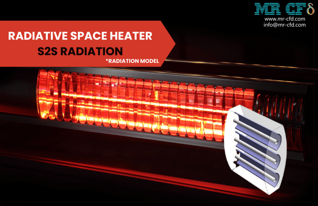
This Project aims to examine the heat transfer occurring between various surfaces within the enclosure of a radiative heater in the absence of a participating medium. Reflector plates are strategically positioned within the heater to facilitate the process of radiation heat transfer between surfaces.
Following the culmination of our investigation, we have successfully acquired the delineations of the temperature and temperature gradient within the confines of the space radiant heater. The depicted contours accurately represent the heat transfer occurring within the radiative heater.
Thermal energy is emitted from heat sources located within the radiant heater. The thermal energy is incident upon the parabolic reflector plates, initiating the subsequent thermal reflection process. This activity results in a higher magnitude of heat energy being dissipated to the external environment. The current CFD Project is the fifth episode of the Radiation Model Training Course.
Roseland
The Roseland model is for situations with a very thick light environment. Unlike other radiation models, this model does not need to define the internal emissivity coefficient in the boundary condition section; the software considers this value equal to one by default. The advantages of this method include low computational cost and no need for transport equations. In contrast, its limitations include usability only in high-light thickness environments and unusability in density-based solution models. Optical thickness is used as a criterion for expressing the amount of radiation intensity absorbed, equal to the absorption coefficient multiplied by the average value of the characteristic length of the object. So if the amount of light thickness was high (greater than three), the Roseland method is used, while the P-1 method for light thickness above one, the S2S method for zero light thickness, and the DO and DTRM are used for all values of light thicknesses. In terms of application, the Roseland method is more suitable for glass applications (due to its high absorption coefficient).
Using ANSYS Fluent software, we execute a numerical simulation of the combustion process of the train inside the tunnel, taking Rosseland radiation into account. This initiative examines the radiation heat transfer caused by the train’s combustion process inside the tunnel. When the combustion reaction occurs, a great deal of heat is produced. This elevated temperature can cause radiation in the surrounding area. The contours associated with temperature, velocity, radiative heat flux, and mass fraction of fuel, carbon dioxide, oxygen, and water vapor have been obtained upon conclusion.
The results indicate that the combustion reaction occurred accurately on the train’s exterior body. The train body spills fuel, which reacts with oxygen in the open air. This combustion reaction generates carbon dioxide and a considerable quantity of thermal energy. In addition, where combustion has occurred, the temperature of the train body and the radiative heat flux are substantially elevated. This CFD Project represents the third segment of the Radiation Model Training Course.
Monte Carlo
The Monte Carlo Radiation Model (MCRM) in ANSYS Fluent is a potent instrument for resolving radiative heat transfer issues. Using statistical methodologies, this model simulates the randomness of photon emission, absorption, and scattering. The MCRM is appropriate for various applications, including combustion, solar radiation, and semitransparent media like glass.
The MCRM is capable of handling complex geometries and unstructured meshes with ease. The model can account for both isotropic and anisotropic scattering. The MCRM can handle spectral dependence, crucial for gases with spectrally dependent absorption and emission characteristics.
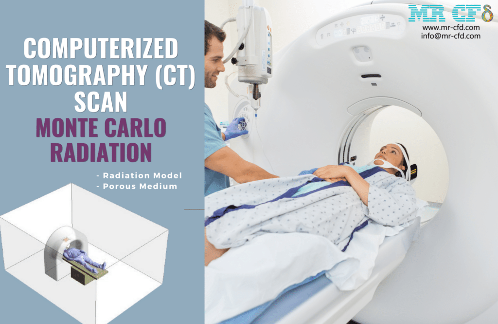
This Project involves conducting a numerical simulation to analyze the thermal radiation of beams in a computed tomography (CT) scan. The ANSYS Fluent software is utilized for this purpose. The existing model pertains to the prone positioning of the patient’s body, which is positioned beneath the CT scan machine. The upper section of the CT scan equipment includes a screen regarded as a light radiation source. The light radiation is introduced into the patient. Subsequently, it traverses the human body, yielding data projected onto the screen positioned in its vicinity, facilitating the visualization of the image through computerized systems.
This study aims to examine radiation’s impact on the human body’s physiological systems. Failure to adhere to medical principles can result in the exposure of the human body to potentially hazardous light rays. The regulation of radiation levels is a significant concern within the medical sector. Following the conclusion, we have successfully acquired the contours of volumetric absorbed radiation, incident radiation, radiation intensity, and changes in radiation temperature.
The contours have been displayed in two modes. In the first mode, the contours are shown within the spatial region above the patient’s body and underneath the radiation source of the CT scan apparatus. This enables us to examine the trajectory of the radiation beam emitted by the CT scan equipment. In the second modality, the contours within the patient’s anatomical structure were visualized to assess the extent to which the rays traverse the patient’s body.
The data accurately demonstrate the trajectory of radiation emitted from the CT scan device’s source. According to the depicted data, these rays penetrate the human body. Quantifying these hazardous radiations within the human body holds significant medical relevance. The present CFD Project constitutes the seventh installment of the Radiation Model Training Course.
Solar Ray Tracing
The solar ray-tracing model is called the ray-tracing algorithm for thermal energy transfer from the sun, which is compatible with other radiation models and is used only for 3D models. Features of this model also include the solar directional vectors, the solar intensity (in terms of direct radiation and scattered emission), and the solar calculator to calculate the direction and intensity of direct radiation using maximum theoretical or equilibrium conditions.
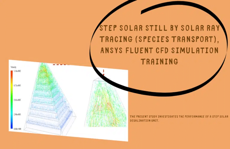
Using ANSYS Fluent, this study investigates the efficacy of a step solar desalination unit. We perform this CFD endeavor and analyze it using CFD simulations. The present model consists of a small chamber with a sloped glass surface on both sides and steps within it, with salt water flowing over the surface of these steps.
Solar radiation heat transfer travels through the glass to the enclosure’s water surface to evaporate the water surface on the enclosure’s steep walls. The resultant vapor contacts the cold surface of the glass and endures a distillation process. Pure water discharged as a result of heated vapor distillation flows down the slope of the glass plate.
After the solution procedure, three-dimensional contours relating to the velocity, temperature, velocity vector, and species mass fraction within the distillation apparatus are obtained. The velocity contours and their vectors illustrate how the generated vapor rises within the distillation apparatus to strike the sloping glass surface at the top.
In addition, by observing the 3D temperature contour, it is evident that the salinity of the water on the stepped platform has increased, causing it to dissipate. In the meantime, the glass layer’s temperature is low enough to cause the vapor to condense and then fall to the lower portion of the distillation apparatus, where freshwater is collected.
In addition, observing the species mass fraction contour reveals that the water mass fraction is one on the stepped platform and glass substrate. Simultaneously, the water volume fraction value decreases within the distillation system’s space, signifying the vapor formation.
Theta Divisions (NӨ) and Phi Divisions (Nφ)
Divisions (NӨ) and phi divisions (Nφ): The number of control angles that break up every eighth of the annular space. Two-dimensional models have only four one-eighth zones due to the symmetry lines in two directions. Thus a total of 4 * NӨNφ for the vector (with angles of Ө and φ) must be solved; As in 3D models, there are eight eighth-region, so a total of 8 * NӨNφ for the vector (with angles Ө and φ) must be solved. These angles are, by default, equal to two. However, more angles are suggested for more complex problems involving specific radiation exchange, which can usually be chosen from three to five. In general, increasing the number of these angles and better discretization will better resolve the effects of small geometrical features or strong spatial variables on temperature, increasing computational costs.
Theta Pixel and Phi Pixel
Theta pixel and Phi pixel: Pixels have bumps on each surface. For gray matter radiation, 1 * 1 pixelation is sufficient; increasing the number of pixel insertions also increases computational cost but has less computational effort than angular segmentation.
Non-gray Model
Generally, surfaces whose radiation is independent of the path are called diffuse surfaces, and surfaces whose radiation is independent of wavelength are called gray surfaces. Therefore, to simulate non-gray radiation models, it is necessary to define spectra of specific wavelengths (with start and end wavelengths in micrometers). Also, increasing the number of optical spectra increases the computational cost.
Emissivity (Boundary Condition)
The proportion of energy emitted by a surface to the energy emitted by a black body (the body most fully absorbing and emitting, or in other words, no object at a given temperature and wavelength can be greater than the black body emits energy) at the same temperature, called the emissivity, which always has a value between zero and one. This diffusion coefficient is used for inlet and outlet boundaries. The rough surfaces also have random radiative reflections and smooth surfaces such as mirrors have reflective boundary conditions. The semitransparent boundary condition is used to model objects such as glass boards in the air, and the opaque model is used to model matte walls that behave like gray objects. Then we can determine the diffuse fraction, which is the fraction of the reflective radiation flux in the form of propagation. When it is equal to 1, all radiation is propagated. When it is equal to zero, that is poor reflection radiation.
Solar Load Model
The solar load model activates the thermal load of solar energy. Solar ray tracing is an algorithm for transferring solar energy compatible with all the radiation models mentioned. Of course, this mode can only be used for 3D models. By selecting this model, the characteristics of solar radiation on surfaces and objects can be determined by defining longitude, latitude, and time zone in the global position section and defining the north and east directions of the object concerning the sun’s radiation in the section. Applied mesh orientation and definition of the days and hours of radiation in the date and time section. The direction of the sun’s rays can also be determined using the Cartesian coordinates in the sun direction vector. By selecting a solar calculator, we can define the direct and diffuse solar irradiation values by the software based on our input data.
Semitransparent & Opaque Boundary Conditions
The semitransparent boundary condition is used to model objects such as glass boards in the air, and the opaque model is used to model opaque walls that behave like gray objects. By activating the participation in the solar ray tracing option, the radiant forces of solar energy affect the selected boundary condition.
Radiation MR CFD Projects
A variety of MR CFD’s initiatives involve radiation simulations. These initiatives span numerous industries and provide engineering insights and solutions to problems. Here are examples of their previous work:
Heat Transfer in Solar Collectors
In this assignment, MR CFD analyzed the heat transfer in solar collectors using radiation simulations. The results assisted in optimizing the Design of the collectors, thereby enhancing their performance and efficacy.
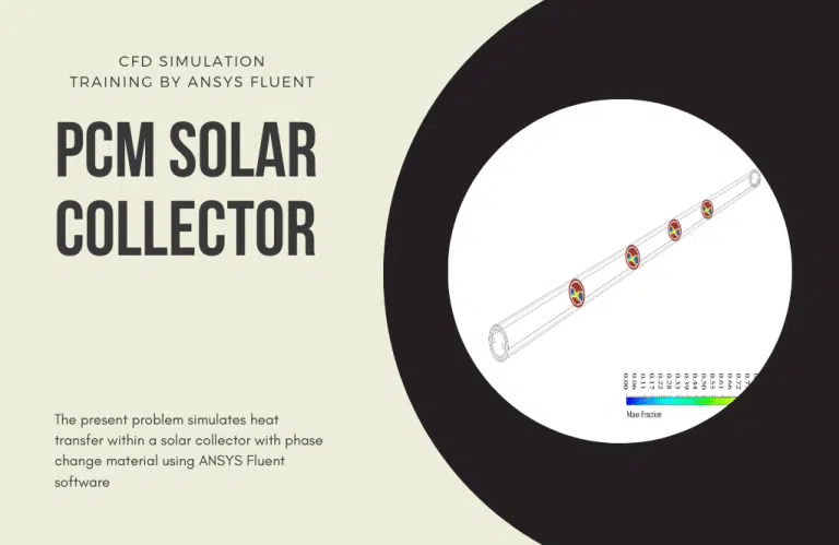
Three concentric layers are arranged in a cylindrical configuration in the vicinity of this region dedicated to phase transition materials. The initial stratum consists of a compact aluminum structure and is characterized as a thermally conductive layer resulting from the absorption of solar light. The subsequent layer is characterized by an interstitial region of air, followed by a layer composed of glass material. This system’s operational principle involves transmitting solar heat through the glass layer, heating the air layer. Heat transmission occurs as it is transmitted to the absorbent layer, subsequently absorbed inside this particular layer.
Heat transfer to space is accomplished by utilizing phase-change materials, resulting in a phase change inside these materials. During daylight hours, when the ambient temperature is elevated, and solar radiation is present, these substances undergo a thermal exchange with the absorber layer, resulting in a portion of the absorbed heat being utilized for the phase transition process, namely the melting phase, inside these materials.
In cold weather conditions, namely at night, phase change materials (PCMs) release the latent heat previously stored in the surrounding environment. This release of heat occurs through the process of phase transition, specifically solidification or freezing. As a result, the water flow inside a U-shaped tube is heated during cold weather conditions.
Upon completion of the solution process, contours representing the pressure, velocity, temperature, and mass fraction of the formed liquid are retrieved from the phase transition material in three-dimensional and two-dimensional forms. The depicted images indicate a phase change in the PCM medium contained within the center cylindrical structure, leading to the generation of liquid in that particular area. The photographs prove that heat is transmitted to the U-shaped tube when comparing the temperatures at its intake and outlet.
Flat Plate Solar Collector, Conjugated Heat Transfer (CHT)
Flat Plate Solar Collectors (FPSC) are extensively employed within the solar sector to convert solar radiation into thermal energy. The effectiveness of floating photovoltaic solar cells (FPSCs) is contingent upon several elements, encompassing the collector’s Design, the materials employed, and the geographical placement of the collector.
This study aims to examine radiation’s impact on the water’s temperature flowing through pipes in a Forward Pointing Solar Collector (FPSC) in Doha. The investigation focuses on three specific time intervals during a day in August. The ANSYS Fluent software is employed for conducting the simulation.
The simulation was performed at three distinct time points on August 10, specifically at 12:00 pm, 3:00 pm, and 5:30 pm. The variation in solar radiation intensity during these periods can be attributed to fluctuations in sun angle and atmospheric conditions.
The findings from the simulation indicate that solar radiation substantially impacts the temperature of water flowing through pipes within a floating photovoltaic solar collector (FPSC) system. At the peak of solar radiation at noon, the temperature of the water contained within pipes can reach a maximum of 301.676 Kelvin. During the time intervals of 3:00 pm and 5:30 pm, it is seen that solar radiation intensity is comparatively lower in comparison to the peak intensity experienced at noon. However, it remains sufficiently substantial to raise the temperature of the water. The water temperature within the pipes was recorded at 300.599 Kelvin and 298.593 Kelvin, respectively.
The simulation further demonstrated the significance of the Rockwool insulator, Aluminum Frame, and Glass cover in mitigating heat loss from the FPSC. The Rockwool insulator effectively mitigates heat loss originating from the lower section of the collector, and the Aluminum Frame and Glass cover minimizes heat loss from the upper and lateral portions of the collector.
It is readily observable that the hydrostatic pressure of a fluid falls as it ascends through a conduit. In summary, this simulation offers significant insights into the impact of solar radiation on the temperature of water flowing through pipes in a Flat Plate Solar Collector (FPSC). Additionally, it underscores the need to employ suitable materials and includes design elements that optimize efficiency and mitigate heat dissipation in floating photovoltaic solar cells (FPSCs).
Thermal Management of Electronic Equipment
MR CFD simulated radiation to comprehend the heat dissipation in electronic devices. This improved the reliability and longevity of the devices by enhancing their thermal management.
Combustion Evaluation
MR CFD utilized radiation simulations to analyze the combustion process in furnaces. The findings provided insights into the heat transfer in the furnace, resulting in a more efficient design.
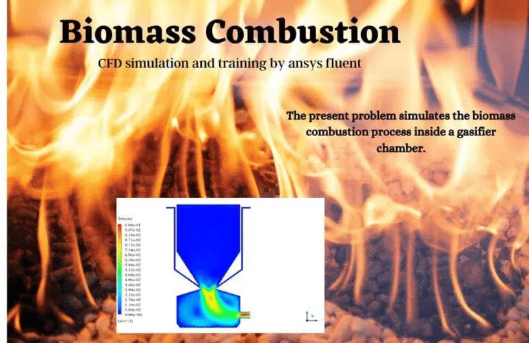
ANSYS Fluent software simulates the biomass combustion process within a gasifier chamber for the current problem. We perform this CFD endeavor and analyze it using CFD simulations. Biomass is the material used for combustion and reacts with the oxidizer. It is a biomass substance derived from wheat straw that reacts with oxygen to produce synthetic gas as a healthful fuel, with multiple gas species serving as reactants or products.
Two discrete inlets in the upper region admit fuel, containing biomass and air, into the chamber. It generates a mass of materials, including ash and semi-combustible lignite, in the chamber’s lower portion. The resultant gas is then expelled from the outlet at the bottom of the chamber to the subsequent stage, entering the furnace to initiate combustion.
In conclusion, we obtain contours relating to pressure, temperature, velocity, and density in two dimensions. We also obtain the mass fraction of species, the mass fraction of water and vapor, and the radiation temperature. The results indicate that, as predicted, combustion is initiated and performed upon the arrival of fuel particles, and the temperature of the combustion chamber rises.
Due to the accumulation of particles on the small inlet surface in the inlet area, the velocity is at its maximal value. The greatest temperature occurred at the opening of the nozzle. The results also reveal carbon accumulation in the geometry’s output region.
This Project uses ANSYS Fluent to investigate the constant combustion of methane and air in a simple extended cubical combustion chamber. We perform this CFD endeavor and analyze it using CFD simulations. Radiation heat transfer must be considered because combustion chamber temperatures are extremely high.
After the solution process, two-dimensional contours relating to the temperature, velocity, species mass fraction, streamlines, velocity vectors, etc., are obtained inside the combustion chamber. The mass flow rate of the mélange at the outlet is 0.004885042 kg/s.
The primary combustion process occurs within the combustion chamber. This is evident in the temperature reaction heat contour, demonstrating that the maximal temperature gradient and maximum reaction heat are observed. Species mass fraction contours also clearly demonstrate the occurrence of the combustion process. For instance, the CO2 mass fraction contour illustrates the abrupt increase in CO2 mass fraction caused by the combustion process.
Radiation Therapy Equipment Design
MR CFD utilized radiation simulations to aid in designing radiation therapy devices in the medical industry. Simulations assisted in ensuring the safety and efficacy of the devices.
Analysis of Building Thermal Comfort
MR CFD conducted radiation simulations to assess the thermal comfort of structures. The findings contributed to the Design of more energy-efficient buildings, which enhanced the well-being of their occupants.
Solar Air Conditioning Training Package
This training package consists of nine distinct CFD simulation projects utilizing the ANSYS Fluent software and relating to solar air conditioning in various locations and conditions. MR-CFD recommends this program to anyone interested in Renewable Energy Engineering, specifically Solar Energy analysis. This package introduces you to various project descriptions, designs, and simulation techniques, considering various related numerical studies.
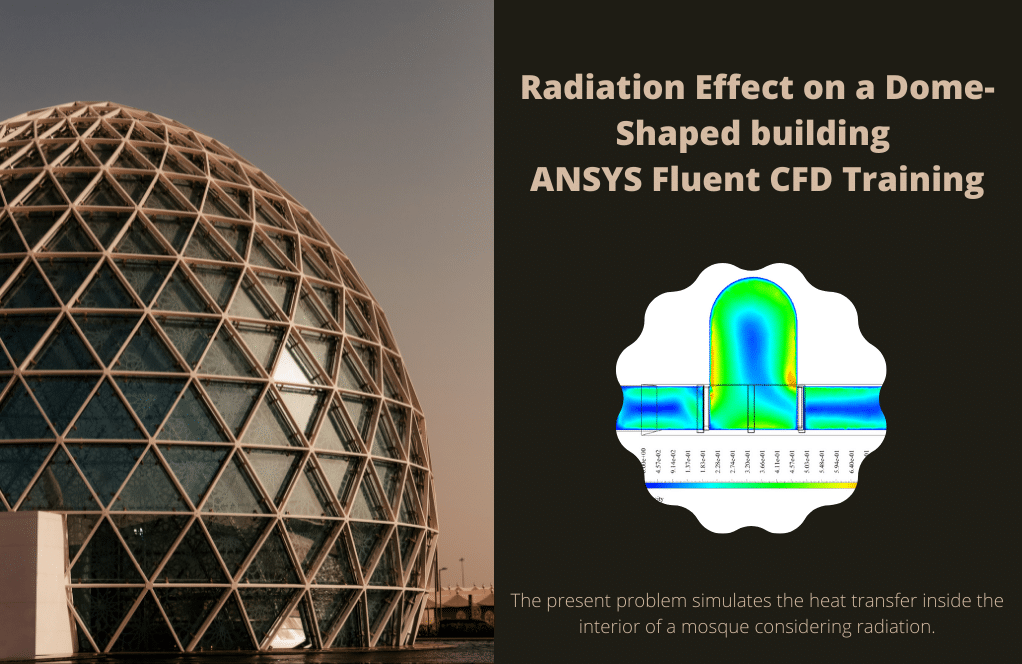
First, begin the training package with a simple project concerning the impact of solar radiation on a home’s HVAC system; then, we will investigate the radiation at various times of the day. Using CFD simulation, we then analyze the effect of shadings, different facade designs, and balconies on the HVAC of a house. Next, we simulate the effect of radiation on workplaces, mosques, and gasoline storage containers. We will then examine a thorough CFD analysis of the Urban Heating Island (UHI).
By studying this fantastic and practical training package, you can claim to be an expert in modeling and analyzing every CFD simulation related to solar radiation and its applications, such as the solar ray tracing model. Then you will be qualified to work as a CFD engineer in the relevant industries.
These projects illustrate MR CFD’s proficiency in radiation simulations and capacity to provide valuable solutions to various engineering and industrial problems. By utilizing sophisticated CFD tools and techniques, we can assist in optimizing system design, enhancing performance, and ensuring safety and efficacy.
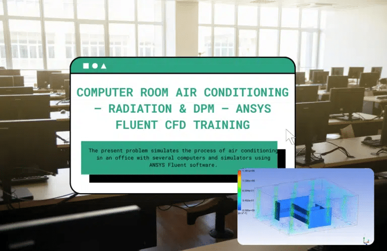
Computer Room Air Conditioning
The current issue is air conditioning simulation in an office environment that includes multiple computers and simulators utilizing the ANSYS Fluent software. The air conditioning system implemented in the present model utilizes a floor heating and ceiling cooling mechanism. Within these systems, buoyancy induces unrestricted heat movement within the confines of the office environment.
The upward movement of hot air and the downward movement of cold air generate a circulating flow, resulting in the air conditioning process due to the difference in density between the two air masses. In this model, the airflow is introduced into the office space through round openings, exhibiting a velocity of 0.6125 m/s and a temperature of 291.1 K. The egress occurs via rectangular apertures located on the roof of the workplace, where the pressure is equivalent to that of the surrounding atmosphere.
Upon completion of the solution procedure, contours representing pressure, velocity, temperature, and three-dimensional velocity vectors are acquired in two-dimensional and three-dimensional formats. Airflow analysis can be conducted by studying these particles’ behavior and displacement characteristics.
Radiation Application in Industrial Companies
Radiation has numerous applications in the industrial sector. It is utilized in several processes, including quality control, safety measures, process optimization, and product development. Here are some prevalent industrial applications of radiation:
Non-Destructive Testing (NDT)
In non-destructive testing methods, such as radiographic testing, radiation is frequently used to inspect the integrity of materials and structures without causing damage. This is typical in aerospace, automobile manufacturing, and construction industries.
Sterilization
Radiation is used in the medical and food industries to sterilize products and equipment. This ensures the products’ safety and quality.
Process Control
Utilizing radiation to monitor and control industrial processes is possible. For example, it can monitor the fill level of containers and measure the thickness of materials on a production line.
Energy Generation
In the energy industry, nuclear reactors utilize nuclear radiation to generate electricity. Nuclear fission generates heat to produce steam, which powers the electricity turbines.
Material Modification
Radiation can alter the properties of materials, such as increasing the heat resistance of polymers or the wear resistance of metals. This occurs frequently in industries such as manufacturing and materials science.
Medical Applications
Radiation is used for various purposes in the medical industry, from diagnosing diseases with imaging techniques to treating diseases with radiation therapy.
These industrial applications demonstrate the versatility of radiation. Radiation can provide valuable solutions to numerous industrial challenges if the proper precautions and regulations are taken.
MR CFD Industrial Experience in the Radiation Field
Some examples of Radiation industrial projects recently simulated and analyzed by MR CFD in cooperation with related companies are as follows:
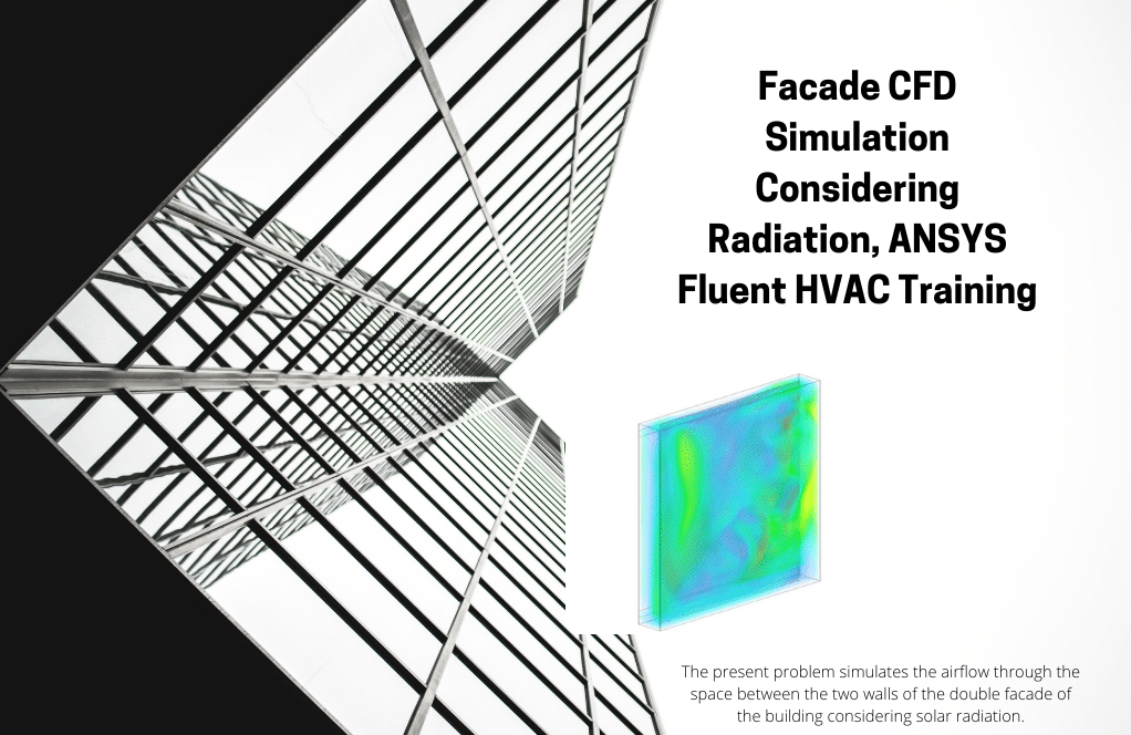
Façade Design Effect on Passive Ventilation of Buildings
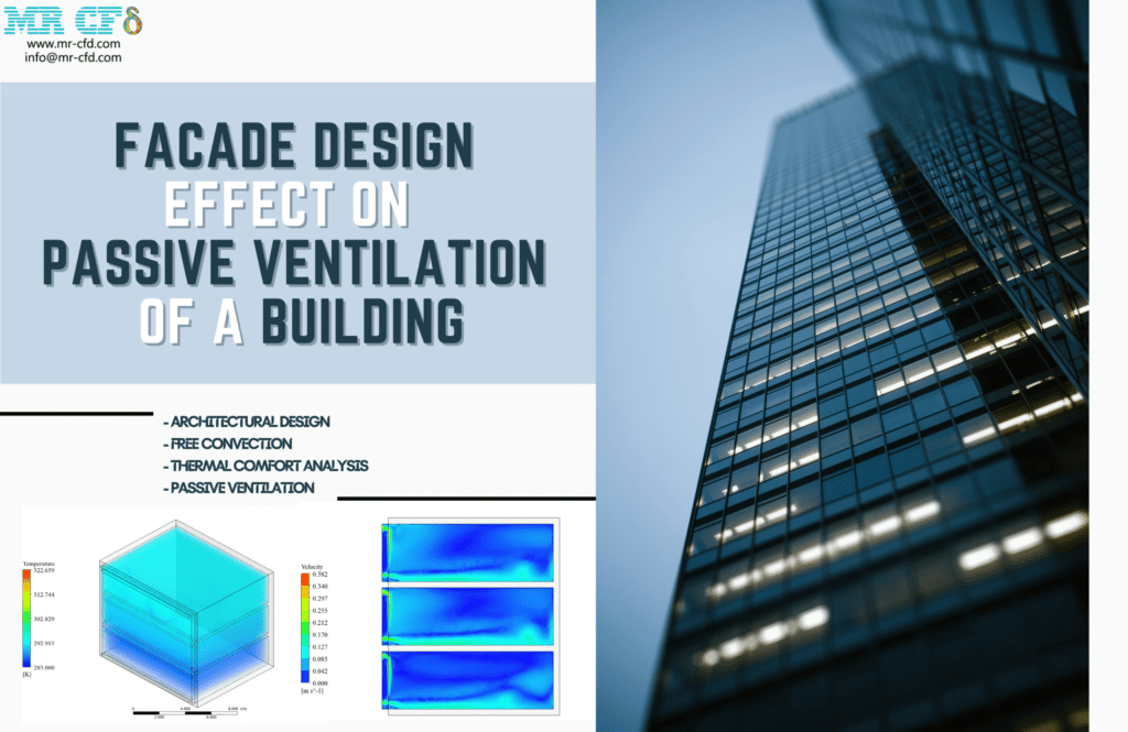
It is one of the building components that allow engineers the freedom to provide a portion of the required energy through Passive ventilation systems. This endeavor simulates a three-story apartment in Sydney, the capital of the Australian state of New South Wales. This study examines various facade conditions to achieve the optimal case, assuring natural ventilation, optimal thermal conditions, and air change per hour (ACH).
In the initial phase, general information is gathered to estimate the geographical and thermal conditions. With coordinates of 151.20 longitude and -33.865 latitude, Sydney has the harshest weather in July and August, with an average temperature of 283K. In addition, the structure had three floors with a cross-sectional area of 80 m2 and a height of 2.8 m.
The client also imposed a limitation by requesting glass facades. As stated, the two primary design objectives are to provide a portion of the building’s energy requirements and natural ventilation as measured by the ACH parameter. Therefore, our specialists devised three distinct facade designs that were predicted to meet the objectives.
Urban Heat Island (UHI) on a Real Zone
Studying Urban Heat Islands (UHI) is one of the world’s most essential and well-liked topics. We examine these issues using CFD modeling. Auckland is a major metropolitan area on New Zealand’s North Island. The country’s most populous urban territory and the fifth-largest city in Oceania.
Auckland is located between the Hauraki Gulf to the east, the Hanau Ranges to the southeast, the Waitakere Ranges to the southwest, and Manuka Harbor to the west. The adjacent hills are forested, and the landscape has 53 volcanic fields. Auckland’s climate is oceanic. Moreover, the National Institute of Water and Atmospheric Research (NIWA) classifies its climate as subtropical. Summers are hot and humid, while winters are moderate and humid.
It is the warmest major New Zealand city. The average daily maximum temperature in February is 23.7 °C (74.7 °F), and in July it is 14.7 °C (58.5 °F). The highest temperature recorded was 34.4 °C (93.9 °F) on February 12, 2009. The lowest temperature, however, was 3.9 °C (25.0 °F).
Occasionally, Auckland experiences air pollution due to fine particle emissions. There are also occasional violations of carbon monoxide guidelines. Even though maritime winds typically disperse pollution relatively rapidly, they can occasionally become visible as smog on calm winter days. The mean high-pressure belt in the New Zealand sector of the Southern Hemisphere is centered near 30° S, causing the country to be dominated by westerly winds.
However, the pressure distribution has a significant deal of daily variation. Occasionally, intense anticyclones and depressions occur in the south and north of the country, respectively. Inverting the normal weather pattern, they induce an easterly flow. These obstructions could be quite persistent. They interrupt the typical westerlies associated with the progression of weather systems to the east.
The objective of this simulation is to examine the effects of maritime winds on Auckland’s urban roads. Consequently, we choose the urban plan of Auckland University of Technology (UHI) to investigate this issue. This study analyzes wind comfort conditions in the region and identifies locations with wind speeds exceeding 3.8 meters per second. For thermal comfort analysis, no location on campus should have a temperature above 295 K.
You may find the Learning Products in the Radiation CFD simulation category in Training Shop. You can also benefit from the Radiation Training Package, which is appropriate for Beginner, Intermediate, and Advanced users of ANSYS Fluent. Also, MR CFD is presenting the most comprehensive Radiation Training Course for all ANSYS Fluent users from Beginner to Experts.
Our services are not limited to the mentioned subjects. The MR CFD is ready to undertake different and challenging projects in the Radiation modeling field ordered by our customers. We even carry out CFD simulations for any abstract or concept Design you have to turn them into reality and even help you reach the best strategy for what you may have imagined. You can benefit from MR CFD expert Consultation for free and then Outsource your Industrial and Academic CFD project to be simulated and trained.
By outsourcing your Project to MR CFD as a CFD simulation consultant, you will not only receive the related Project’s resource files (Geometry, Mesh, Case & Data, …), but also you will be provided with an extensive tutorial video demonstrating how you can create the geometry, mesh, and define the needed settings (preprocessing, processing, and postprocessing) in the ANSYS Fluent software. Additionally, post-technical support is available to clarify issues and ambiguities.


