CFD Project Outsourcing
Outsource your CFD project to the MR CFD simulation engineering team. Our experts are ready to carry out every CFD project in all related engineering fields. Our services include industrial and academic purposes, considering the ANSYS Fluent software's wide range of CFD simulations. By outsourcing your project, you can benefit from MR CFD's primary services, including CFD Consultant, CFD Training, and CFD Simulation.
The project freelancing procedure is as follows:
An official contract will be set based on your project description and details.
As we start your project, you will have access to our Portal to track its progress.
You will receive the project's resource files after you confirm the final report.
Finally, you will receive a comprehensive training video and technical support.
What is Phase Change Material (PCM)?
Phase Change Materials (PCMs) refer to substances that can absorb and release thermal energy due to melting and freezing. When a phase change material (PCM) undergoes freezing, it liberates a significant quantity of energy in latent heat, maintaining a consistent temperature. In contrast, melting a phase change material (PCM) involves absorbing significant heat from the surrounding environment while maintaining a relatively stable temperature.
Fundamental Characteristics of Phase Change Materials (PCMs) Phase Change Materials (PCMs) possess several key features that make them suitable for various applications. These fundamental characteristics contribute to their unique thermal energy storage capabilities and distinguish them from other materials. This
- Energy Storage
Phase Change Materials (PCMs) find extensive utilization in many applications, predominantly for thermal energy storage and retrieval. In a solar heating system, it is possible to store surplus heat within a phase change material (PCM) to be utilized during periods of less solar radiation, such as nighttime or overcast days.
- Thermal Regulation
Due to their capacity to absorb and emit heat consistently, phase change materials (PCMs) are useful in regulating temperature across many domains, including architectural structures, electronic systems, and textile products.
- Diverse Spectrum of Transition Temperatures
Phase change materials (PCMs) exhibit a broad spectrum of transition temperatures, spanning from -100°C to 1000°C, rendering them very versatile for various applications.
- Sustainability
Phase change materials (PCMs) can undergo numerous phase change cycles without experiencing substantial degradation. This characteristic renders them a viable and environmentally friendly option for storing thermal energy.
This section presents examples of phase change materials (PCMs) often used in various applications. These examples illustrate the diverse range of PCMs and corresponding phase change temperatures.
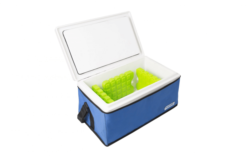
Inorganic phase change materials (PCMs), specifically salt hydrates, are widely employed in various applications. One notable feature of these materials is their elevated heat of fusion and exceptional thermal conductivity; nonetheless, it is important to acknowledge that they may be susceptible to supercooling.
Eutectic phase change materials (PCMs) refer to blends of organic or inorganic compounds strategically designed to possess a melting point lower than that of the individual constituents.
In summary, phase change materials (PCMs) are crucial in industries prioritizing thermal energy storage and temperature control. These systems offer passive and reliable solutions to regulate temperature effectively, enhance energy efficiency, and provide a comfortable environment.
What is Solidification & Melting?
The transition from a solid to a liquid is known as melting. A pure substance begins to melt at a specific, fixed temperature known as the melting point.
A phase transition in materials that produces a solid is known as solidification, commonly called freezing. This typically happens when a liquid’s temperature is dropped below its freezing point. While most materials have a freezing and melting point at the same temperature, not all materials do. Hence, “freezing point” and “melting point” are not always synonymous.
Thermal energy storage in PCM is obtained during the phase change process. During the phase change from solid to liquid, it absorbs heat from the environment and returns heat to the environment during the liquid-to-solid phase change. Therefore, PCMs have various melting (Liquidus) or freezing (solidus) temperatures and are used in cooling and heating systems. Solidification and melting are fundamental phase transition phenomena in various materials.
Solidification
Solidification is a physical process in which a substance transitions from a liquid or gaseous state to a solid state. Solidification, alternatively referred to as freezing, is the phenomenon by which a liquid transitions into a solid state due to a reduction in temperature below its designated freezing point. Essentially, it denotes how a substance changes from liquid to solid.
During solidification, the particles experience a reduction in their kinetic energy. Consequently, the particles exhibit reduced velocity, increasing the magnitude of intermolecular attractive interactions. As a result, these forces attain sufficient strength to compel the particles to assume a stationary arrangement, giving rise to forming a solid state. One instance of solidification can be observed in the process of water freezing, resulting in ice formation.
Melting
The melting process refers to transforming a solid substance into a liquid state due to applying heat. The melting phenomenon involves the transformation of a solid substance into its liquid state, occurring at a well-defined temperature and pressure referred to as the melting point. During the melting process, a substance absorbs heat energy, which is utilized to induce a structural transformation from a highly organized and rigid solid state to a less organized and more fluid liquid state. One instance of melting can be observed in converting solid ice into its liquid form, water.
Solidification and melting are crucial phenomena in various scientific and industrial domains, encompassing metallurgy, manufacturing, food processing, and climate research.
How can Solidification & Melting (PCM) CFD simulation be applied in Engineering and Industries?
Energy Storage
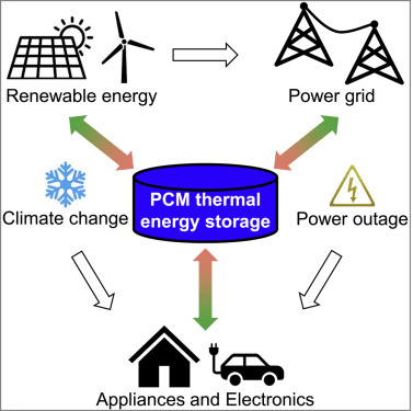
Energy storage is a critical component of modern energy systems. It plays a crucial role in balancing the supply and demand of electricity, especially in the context of intermittent renewable energy sources. Phase change materials (PCMs) are extensively utilized in energy storage systems because they can efficiently store and release significant quantities of thermal energy during the phase transition phenomenon. Computational Fluid Dynamics (CFD) simulations can enhance the optimization of these systems by accurately predicting the melting and solidification behavior of the Phase Change Material (PCM), leading to improved energy efficiency.
Thermal Management in Electronics Systems
The topic of electronics cooling is an essential aspect of thermal management in electronics systems. Efficient cooling techniques are crucial for maintaining optimal operating temperatures and preventing overheating in electronics. PCMs, also known as phase change materials, are employed in electronics to mitigate the issue of component overheating. Computational Fluid Dynamics (CFD) models can accurately represent the melting phenomenon of Phase Change Materials (PCM) when they absorb thermal energy from electrical devices. This capability aids in the development of enhanced cooling systems with improved effectiveness.
The Process of Building and Construction
Phase change materials (PCMs) are employed in the composition of building materials to enhance thermal comfort and mitigate energy consumption associated with heating and cooling processes. Computational Fluid Dynamics (CFD) simulations provide the capability to forecast the performance of these materials across various weather situations.
Food Industry
The food industry is a sector that encompasses many activities related to the production, processing, distribution, and consumption of food products. It plays a crucial role in meeting the nutritional needs of the population and contributes significantly to
Within the realm of the food business, phase change materials (PCMs) find application in refrigeration systems to sustain a consistent temperature. Computational fluid dynamics (CFD) simulations can be utilized to optimize the design of these units, aiming to achieve optimal efficiency.
Metallurgical Processes
Metallurgical processes refer to a set of procedures and techniques used in the field of metallurgy for the extraction, purification, and transformation of metals. Solidification processes are key in metallurgical industries, namely casting and welding. Computational Fluid Dynamics (CFD) simulations can enhance comprehension and regulation of these processes, facilitating product quality enhancement.
In brief, computational fluid dynamics (CFD) simulations utilizing the phase-change method (PCM) offer significant utility for engineers in designing and optimizing diverse systems and processes across many industries.
MR CFD services in the Solidification & Melting (PCM) Simulation for Engineering and Industries
With several years of experience simulating various problems in various CFD fields using ANSYS Fluent software, the MR CFD team is ready to offer extensive modeling, meshing, and simulation services. Simulation Services for Solidification & Melting CFD simulations are categorized as follows:
- Simulation and analysis of PCM application in Tank Storage, Fuel Tank, etc.
- CFD Simulation of PCM inside Various Types of Heat Exchangers.
- Modeling of PCM inside Different Types of Tubes (Finned Tube, Triplex Tube, etc.)
- Simulation of Providing Indoor Locations Thermal Comfort inside
- Analysis of PCM application in solar Heating Devices.
- CFD Simulation of Improving Battery Performance using PCM Materials.
- Analysis of Passive Ventilation using Phase Change Material
- …
MR CFD possesses extensive expertise in Computational Fluid Dynamics (CFD) simulations, specifically focusing on Solidification and Melting (PCM) simulations. The establishment provides a range of services.
Computational Fluid Dynamics (CFD) Simulations Tailored to Specific Requirements
MR CFD can conduct tailored computational fluid dynamics (CFD) simulations to simulate and evaluate your application’s solidification and melting phenomena. This can facilitate comprehension of the system’s behavior and enhance its performance optimization.
Selection and Design of Phase Change Materials (PCM)
This section will discuss selecting and designing phase change materials (PCM). The services provided by MR CFD include assisting in the selection of an appropriate Phase Change Material (PCM) for a given application and designing a system that optimizes its utilization. This entails determining the most favorable dimensions and configuration of the phase change material (PCM) components and their organization within the system.
Analysis of Thermal Properties
The thermal analysis capabilities of MR CFD encompass a comprehensive examination of your system, encompassing heat transport phenomena, temperature distribution patterns, as well as processes involving phase changes. This approach can potentially enhance the system’s thermal efficiency and mitigate issues related to overheating.
Training in Software Development
MR CFD provides training programs encompassing various computational fluid dynamics (CFD) software packages, enabling individuals to conduct simulations independently. The offerings encompass instructional sessions, interactive group sessions, and personalized mentoring.
Provision of Technical Assistance
MR CFD offers continuous technical assistance to ensure the seamless operation of your simulations and achieve precise outcomes. The services encompassed under this scope encompass troubleshooting, software updates, and counseling about simulation methods.
In brief, MR CFD provides an extensive array of services to assist individuals in their solidification and melting (PCM) simulations, hence facilitating the attainment of their engineering and industry objectives.
Solidification and Melting in Fuel Tank
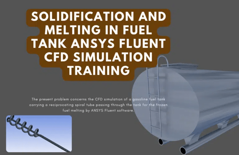
One problem with frozen gasoline fuel is that the temperature drops when it is cold outside or stored in a cold place. When the temperature of the fuel drops, sediments, and glues come off first. Then, as the temperature drops, the heavy hydrocarbon molecules freeze and become mummies. To keep gasoline from freezing, the temperature needs to be raised in the tanks where it is stored. One way to raise the gasoline temperature in the fuel tank is to run hot fluid through pipes. Interestingly, helical tubes can be used when there isn’t enough room because there is more heat transfer in a given area. Most of the ice melts near the spiral pipes. So, as the cooking process goes on, the percentage of liquid mass will increase. This study is done in a short amount of time, and the results are known when the scenario is over.
With ANSYS Fluent, this example is about how bitumen melts inside a bitumen tank. Bitumen is a substance that gets more concentrated when it gets cold. In other words, the asphalt inside the tank slowly freezes because of the cold. So, hot water pipes are put inside these tanks to raise the temperature of the bitumen inside the tanks and keep it from freezing. This project uses a 2D asphalt tank with conditions that change over time.
Several rows of hot water pipes are set up inside the tank. The asphalt material goes into the tank at a low temperature. When it gets heat from the pipe wall, its temperature goes up. A solidification and melting model is used in this scenario to describe phase change materials.
After the math, you get 2D and 3D outlines for temperature, temperature gradient, pressure, speed, liquid fraction, and liquid fraction gradient. The shapes show that the bitumen temperature goes up near the hotlines. When the temperature goes up, the asphalt starts to melt. Because of this, the asphalt doesn’t freeze.
In this project, an ANSYS Fluent simulation was used to study the effects of a Sandwiched PCM CFD Simulation between two concentric cylindrical tubes. We do this CFD job and use CFD analysis to look into it. After the answer, two-dimensional curves show the speed, temperature, and liquid volume fraction. For example, we can see from the liquid volume fraction curve that the PCM material near the hot wall changes from solid to liquid as the temperature rises, creating a liquid layer. The thickness of this layer gets thicker over time.
PCM in Glass-Coated Circular Chamber
In this problem, ANSYS Fluent software is used to model how a PCM works in a glass-coated circular chamber. We do this CFD job and use CFD analysis to look into it. This PCM is spread out evenly in the chamber. PCMs are made of inorganic or organic compounds that can take and store much thermal energy that is not being used.
When these materials change from solid to liquid or liquid to solid, they store heat energy. When they change from solid to liquid, they take heat from the environment, and when they change from liquid to solid, they give heat back to the environment.
The temperatures at which these materials melt, or freeze are different. So, PCM is used in heating and cooling systems. For example, on a hot day, these materials absorb heat from the environment as latent heat and melt. When the air is cooler, they return the heat to the environment at night by changing their phase and solidifying.
A glass coating has been put around the chamber with the phase change material for this modeling. This coating is kept at a steady temperature of 338.15 K and transfers heat to the phase change material. At the end of the solution process, liquid mass fraction and temperature outlines were measured at different times every 40 minutes. You also get a graph that shows how the amount of liquid mass percent changes over time. As time passes, it’s clear that the liquid and solid mass fractions go down.
How to Model Solidification & Melting (PCM) inside ANSYS Fluent
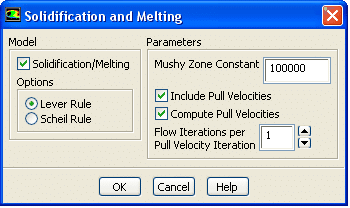
Using Ansys Fluent, fluid flow problems involving solidification and melting can be resolved at a single temperature or over various temperatures. Ansys Fluent employs an enthalpy-porosity formulation rather than tracking the liquid-solid front explicitly. To account for the pressure decrease from solid material, the liquid-solid mushy zone is a porous zone with a porosity equal to the liquid percentage. The turbulence equations also incorporate sinks to account for the reduced porosity in the solid sections.
Ansys Fluent models the solidification/melting process using the enthalpy-porosity method. The melt interface is not specifically tracked in this method. Instead, each cell in the domain has a value known as the liquid fraction, representing the portion of the cell volume in liquid form. At each iteration, the liquid fraction is calculated using an enthalpy balance.
The liquid fraction is found in the region between 0 and 1 in the mushy zone. The “pseudo” porous medium representing the mushy zone has a porosity that falls from 1 to 0 when the substance solidifies. The porosity is zero when the material has entirely solidified in a cell, which causes the velocities likewise to be zero.
Simulating solidification and melting processes of Phase Change Material (PCM) in ANSYS Fluent encompasses multiple procedural stages. Presented below is a comprehensive manual:
Geometric Modeling and Mesh Generation
To begin, it is necessary to generate the geometric representation of the system using computer-aided design (CAD) software. Subsequently, this geometry can be imported into ANSYS, a widely used software for engineering simulations. Next, proceed to generate the mesh for the given geometry. The precision of the simulation is contingent upon the quality of the mesh.
Properties of the Material
In this section, we will discuss the material’s properties under consideration. The material properties of Phase Change Materials (PCMs) encompass a range of characteristics that define their behavior and performance. These qualities include thermal conductivity, specific heat capacity, latent heat of fusion, density, viscosity, and thermal stability. This encompasses the properties of specific heat, thermal conductivity, and latent heat of fusion. These properties must exhibit a temperature dependence to simulate the phase change process effectively.
Selection of the Model In this step
The process of selecting the appropriate model for the given problem is discussed. Please choose the appropriate energy equation and viscous model. To select the solidification/melting model, please opt for the “Solidification and Melting” alternative.
Boundary Conditions
In this step, we will discuss the boundary conditions that must be considered in our analysis. Boundary conditions are the constraints or limitations imposed on a system or problem. They define the values or behaviors at the boundaries or Please describe the boundary conditions utilized in your simulation. This encompasses the initial temperature of the phase change material (PCM) and the heat transfer conditions at the system’s boundaries.
Solution Approaches and Experimental Controls
Select suitable methodologies and measures for resolving the issue at hand. This encompasses the discretization schemes employed for the equations and the under-relaxation factors utilized.
Initialization and calculation processes
Commence the computation by initializing the solution based on the predefined initial circumstances. The residuals should be monitored to assess the solution’s convergence.
Post-Processing
In this step, post-processing is conducted to refine and enhance the output of the previous steps. Once the computation is completed, the obtained results should be analyzed using the available post-processing tools. The factors above encompass the spatial variation of temperature, the proportions of solid and liquid phases inside the phase change material (PCM), and the speeds at which heat is transferred.
It should be noted that these instructions serve as a general reference and may be subject to variation based on the exact application and version of ANSYS Fluent being utilized.
Solidification & Melting (PCM) MR CFD Projects
Mr. CFD possesses an extensive repertoire of projects encompassing solidification and melting process simulations, specifically about phase change materials (PCMs). The following examples are provided:
Solar Energy Storage
The utilization of phase change materials (PCMs) in a solar energy storage system was simulated by MR CFD. The project encompassed the development of a computational model to simulate the diurnal melting and nocturnal solidification of the phase change material (PCM) as it underwent heat absorption from solar radiation and subsequent heat release.
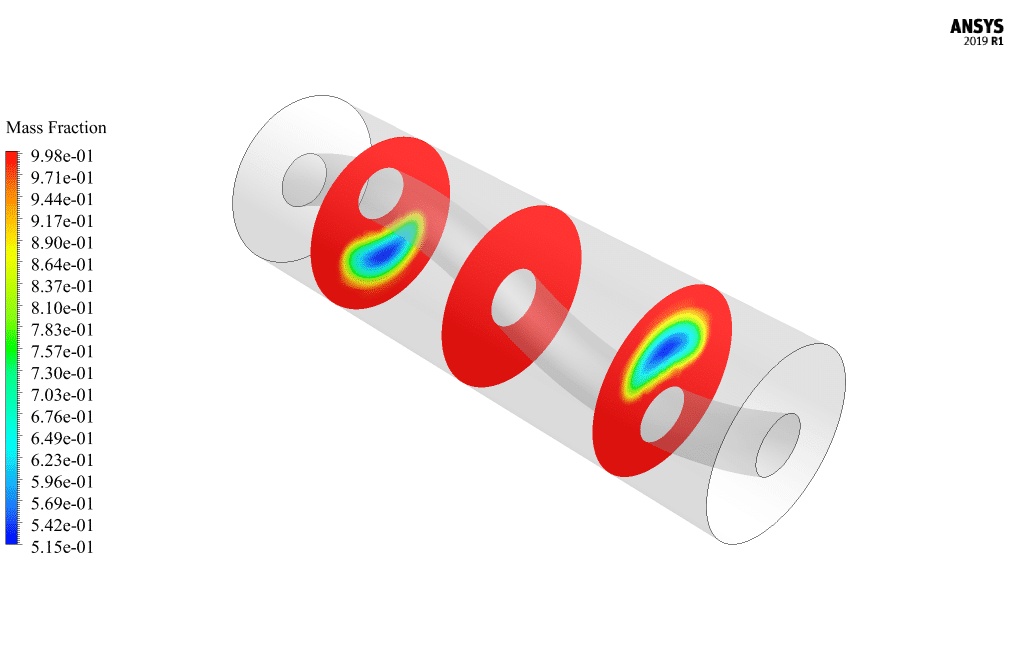
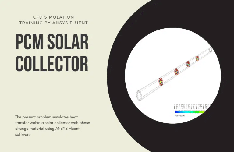
ANSYS Fluent software models how heat moves through a PCM solar collector. We do this CFD job and use CFD analysis to look into it. The latest model is tube-shaped, like a U that moves water. A cylinder-shaped space of phase change material (PCM) is used around this U-shaped tube.
Three layers are put in a cylinder shape around this space for phase change materials. Its first layer is a solid body made of metal. This layer is called a solar radiation heat-absorbing layer. The next layer is an air gap, and then there is a layer of glass. This method works because the heat from the sun goes through the glass layer and heats the air layer. This heat is sent to the absorbing layer, which soaks up the heat.
With phase change materials, this heat is sent into space to change the state of these materials. During the day, when the air is warm, and there is sunshine, these materials get some of the sun’s heat through the absorber layer. Part of this heat is used for these materials’ phase change or melting process.
Then, during cold weather (at night), these PCMs return the latent heat stored in the environment to the nearby environment by changing the phase, i.e., the freezing (solidification) process, which heats the water flow inside the U-shaped tube. At the end of the solution process, outlines in three dimensions and two dimensions are made from the phase change material that shows the pressure, velocity, temperature, and mass fraction of the liquid made.
The pictures show that the PCM medium inside the center cylinder has changed phase, causing the liquid to form in that area. When the temperatures at the tube’s entrance and exit are compared, it is also clear that heat is moved to the U-shaped tube.
Solar Heater of Water Tank with PCM
This example looks at how ANSYS Fluent software affects the solar heater of a water tank and how PCM works. We do this CFD job and use CFD analysis to look into it. Phase-change materials can change from solid to liquid and back over various temperatures, almost always the same. When these materials change phase, they generally exchange much energy, called latent phase change heat.
This large amount of heat is exchanged in a way that is in sync with nature and works naturally and smartly as the temperature around it changes. These materials are now used in sun heaters and other places to store energy uniquely. The need for energy is growing, and fossil fuels, which are limited and pollute the environment, can’t keep up. This makes it more important than ever to find new energy sources. Solar energy is one of the most commonly used types of energy.
PCMs with much latent heat can store thermal energy, especially solar energy, which has become very common in recent years. The use of phase-change materials in the water tank of solar water heaters is a new idea now being thought about. In this project, PCM encased in a solar water heater has been looked at from different angles, such as the effect of PCM material melting and freezing temperatures, PCM material volume, and a comparison with no PCM material.
The inner wall of the PCM space is a wall with a thickness of 0.0015 m and a temperature of 603.3 K. The wall boundary condition with the Adiabatic condition is used for the outer wall of this area. After running a simulation, the temperature, speed, pressure, and liquid volume fraction outlines are found. The findings prove that the temperature and the amount of liquid are the same every time.
As the inner wall’s thermal boundary state raises the temperature of the PCM, the amount of liquid in the PCM also goes down. Because as the temperature goes down, the phase change from liquid to solid happens, and the liquid turns into a solid.
Building Insulation
The modeling of a building insulation system utilizing Phase Change Material (PCM) was conducted by MR CFD. The objective was to enhance the structure’s thermal efficiency by regulating the phase change material’s phase transition mechanism (PCM).
This project uses the ANSYS Fluent program to simulate PCM for passive ventilation. We do this CFD job and use CFD analysis to look into it. Phase-change materials can store energy and then release it when it’s needed. So, PCMs can cool or heat the surroundings and store heat by changing between solid and liquid states.
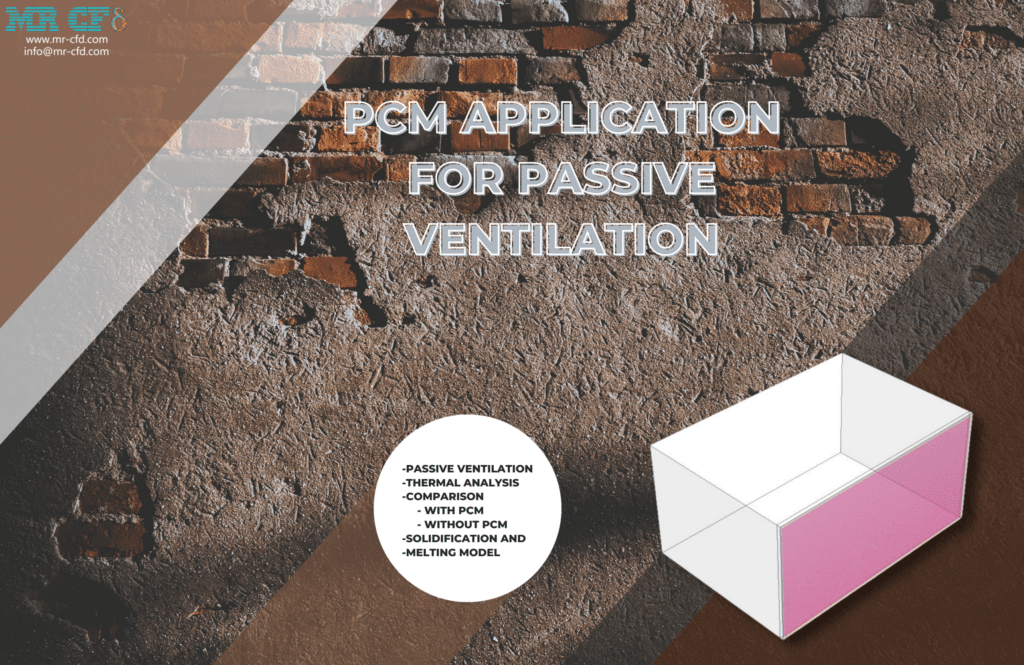
So PCMs move heat without using any mechanical device. So, these devices are part of the group of passive ventilation. The buoyancy effect is the key to how this passive air system works. Changes in temperature cause differences in density, which leads to spontaneous convection.
We made a passive airflow system model as part of this project. This job was done in two steps. In the first step, we only looked at how heat moved through a room because of natural circulation. We thought that one of the walls was always giving off heat. This heat comes from the warm air around it and the sun’s rays.
In the second step, we used a PCM panel to heat the same wall. Our goal was to find out how PCMs affect how heat moves. After running the program, we plotted the room’s average temperature over time. This plot shows the difference between two modes: with PCM and without PCM.
Also, we got velocity vectors and temperature outlines in both 2D and 3D. We want to determine what happens when PCM is used in passive airflow. In the first simulation, the data show that the temperature increases as time passes. The temperature increases because the wall gives off heat, which moves around the room. In the second example, the temperature goes up with the least amount of slope. Even though there is a heat flow, the PCM layer between the heat flux and the room space makes a difference. So, these things that change phase get heat from latent heat. Because of this, there isn’t much heat in the room.
Thermal Management by PCM in a Room Wall
A Phase Change Material gives off or takes in enough energy when it melts or freezes. Because they melt and harden at certain temperatures, they can be used to control the temperature. When PCM melts, it can take in a lot of heat energy, which it gives back when it hardens. PCMs are used in many places where storing energy and keeping temperatures fixed are important. It has heating pads, cooling for telephone switch boxes, and fabrics for beds and clothes.
In this project, a square room with a wall made of three layers of different materials was built. From the outside to the inside, the layers of the wall are Brick, Trimethylolethane/water (PCM), and Concrete. The outside of the Brick is exposed to a heat flux of 100 w/m2. Brick, Trimethylolpropane/water, and concrete all have low thermal transfer so that the room temperature won’t change quickly. The fourth lesson of the ANSYS Fluent General Training Course is this CFD project.
At the end of finding an answer, two-dimensional contours and vectors show the water’s pressure, temperature, turbulence kinetic energy, and speed. It would take about six days for the volume fraction to reach 1. It means that all of the Trimethylolethane/water Phase Change Material melts. It shows how long the object needs to store the energy it gets from radiation.
Also, the temperature inside the house rises very slowly because the materials that make up the walls (brick, Trimethylolethane/water, and concrete) don’t let much heat through. This program proves that the PCM can store energy and then use it at the right time. This means that less energy and power are used.
ANSYS Fluent software is used to simulate air conditioning with PCM. In general, phase change materials are made of organic compounds that can take and store a lot of heat energy that is not being used. Thermal energy is stored in these materials when they change from solid to liquid or liquid to solid. When they change from solid to liquid, they take heat from the room (which cools the room during hot hours) and give heat back to the room when they change from liquid to solid (which warms the room during cold hours).
At the end of the solution process, the liquid’s pressure, speed, temperature, and mass fraction are shown on two-dimensional outlines. Since the way a phase change material works depends on time, the transient solver is used, and the results are taken at different points in the modeling process to get the results over time. Based on the liquid’s temperature and mass ratio, we can say that the number of liquids produced increases over time. The pictures also show that pressure and speed level out over time and simultaneously have the same values.
Electronic Cooling
The utilization of Phase Change Materials (PCMs) in electronic cooling systems has gained significant attention in recent years. During the phase transition, PCMs can absorb and release large amounts of thermal energy. The MR CFD project focused on applying phase change materials (PCM) for cooling electrical devices. The simulation replicated the phase change material’s phase transition phenomenon (PCM) as it absorbed thermal energy from the electronic components, mitigating the risk of excessive heat accumulation.
Battery Cooling (Thermal Management) by PCM
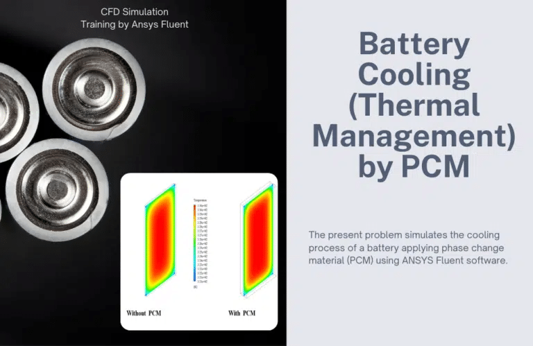
This work aims to find out how well phase-change materials work to cool down the battery. We get two-dimensional and three-dimensional temperature maps after finding an answer. At the end of the simulation, we compare the temperature contours in both steps.
Also, we get a picture that shows how the battery’s average temperature changes over time for the two states with and without phase change material. In an hour, we’ll show this chart. The data show that coating the battery’s body with a phase change material will cool the battery and slow the rate at which its temperature rises. In the second stage of the simulation, two-dimensional and three-dimensional outlines of the volume fraction of liquid in the phase change material are made to show how it affects heat transfer with the battery body.
Food Preservation
In food preservation, the utilization of Phase Change Materials (PCM) has garnered significant attention. The modeling of a food preservation system utilizing Phase Change Material (PCM) was conducted by MR CFD. The project entailed utilizing a model to simulate the phase change material’s phase transition phenomenon (PCM) to regulate the temperature within a specified range, guaranteeing the preservation of food freshness.
PCM Components in Hot Water Tank Thermal Analysis (Load & Discharge)
A Phase Change Material (PCM) is a material that gives off or absorbs enough energy when its state changes to heat or cool something. Most of the time, the change will happen from one of the first two basic states of matter—solid or liquid—to another.
The phase shift can also happen between non-classical states of matter, like when a material changes from conforming to one crystalline structure to conforming to another, which could be a higher or lower energy state. PCMs can store and release much more energy than reasonable heat storage because they can melt and solidify at the Phase Change Temperature (PCT).
Heat is taken or released when a material changes from solid to liquid or liquid to solid or when its internal structure changes. This is why PCMs are called Latent Heat Storage (LHS) materials. The system is made up of 16 PCM capsules that are put in the water tank. Hot water flows through the domain at 0.5 m/s and 335 k. When the PCMs are fully liquid, cold water comes into the system and cools down the PCMs. As the PCMs cool down, they start to solidify.
In the first case, the graph of the average temperature of the environment and PCMs shows that adding hot water raises the temperature of the environment, which raises the average temperature of the PCMs and starts the melting process in 343 seconds.
It gives. After 1500 seconds, all PCMs have melted, and cold water flows into the domain. These results can be seen in the average temperature diagram, and the average temperature of the domain goes down. PCMs slowly give off the heat they have stored, so their normal temperature drops more slowly. The PCMs start to solidify after 500 seconds in the cold water, and after 4500 seconds, they are fully solid.
ANSYS Fluent software simulates how phase change materials (PCM) work in a storage tank for this situation. We do this CFD job and use CFD analysis to look into it. These PCMs comprise a group of spherical shapes inside a tall cylindrical storage tank. These PCMs aim to ensure that water from the inlet pipe at the top of the tank flows into the room inside the tank at 0.1 m/s and 343 K.
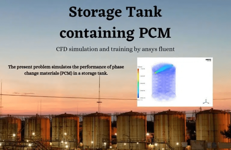
This simulation has been done in several different ways. For example, two types of PCM of paraffin and sat-g have been done in circles with a 4 cm and 5 cm radius and at two different melting temperatures of 333.15 K and 332 K, respectively. This study aimed to look into the fluid and thermal behavior of PCMs and change the ratio of the liquid mass fraction based on the size of the PCMs (the diameters of the spheres), the temperature at which they melt, and the material.
We get two-dimensional and three-dimensional outlines of pressure, temperature, velocity, and liquid and solid mass. These lines have something to do with the last second of the process. During the exercise, we also get a graph that shows how the mass fraction of the PCM has changed over time. The picture shows that the more PCM material melts, the longer it takes to dissolve. Up to this point, some PCM has melted, which has caused the temperature of the tank to rise. The air pressure is lower in places where the temperature is higher.
Heat Exchangers
Phase Change Materials (PCMs) have gained significant attention in the field of heat exchangers due to their unique thermal properties. PCMs are substances that may undergo a phase transition, such as solid-to-liquid or liquid to The project undertaken by MR CFD focused on the utilization of phase change materials (PCM) inside a heat exchanger system. The objective of the simulation was to improve the heat transfer efficiency of the exchanger by optimizing the phase change process of the phase change material (PCM). Each of the projects above showcases MR CFD’s proficiency in conducting simulations related to Solidification and Melting (PCM) and their aptitude in using this technology across various applications.
ANSYS Fluent software models a phase change material solidifying and melting inside a shell and tube heat exchanger. Based on the reference article [Experimental and computational development of a shell and tube heat exchanger as a PCM thermal storage system], numerical simulations have been done, and the results have been compared to the results in the paper and found to be accurate.
The article’s findings come from both experiments and computer simulations. In general, phase change materials are made of organic compounds that can take and store a lot of heat energy that is not being used. When these materials change from solid to liquid or liquid to solid, they store thermal energy. When they change from solid to liquid, they take heat from the environment (which cools the environment); when they change from liquid to solid, they give heat back to the environment (which warms the environment).
In this experiment, the phase change material is RT50-type paraffin. This means that it has a density of 820 kg/m3, a specific heat capacity of 2000 j/kg.K, and a thermal conductivity of 0.2 W/m.K. Also, the viscosity of a phase-change material varies on the temperature and is described by a UDF function that is a temperature-dependent exponential function.
A copper shell-and-tube heat exchanger is filled with water at a mass flow rate of 0.008318 kg/s and a temperature of 343.15 K. The water runs into the inner tube of the heat exchanger, and the phase change material is put inside the shell part of the heat exchanger.
At the end of the solution process, a graph shows how the temperature of the part of the shell containing the phase change material changed over time. This graph is based on the time it took for the material to melt completely. The diagram in Figure 8 of the reference piece is compared to this one, showing how temperatures change to ensure they are the same. The article’s graph shows the results of both actual work and CFD simulations.
Comparing the results of the current numerical modeling to the results of the numerical and experimental work in the article shows that the results are accurate enough. Also, pressure, temperature, and liquid mass fraction-related two-dimensional and three-dimensional outlines have been found.
ANSYS Fluent software models heat transfer in a triplex tube heat exchanger with phase change material (PCM). This simulation is based on an article called “Internal and external fin heat transfer enhancement technique for latent heat thermal energy storage in triplex tube heat exchangers,” Its results are compared to the results in the piece to ensure they are correct. The triplex tube heat exchanger is made up of two tubes that are aligned with each other. These tubes split the cross-section of the heat exchanger into three sections, or tubes.
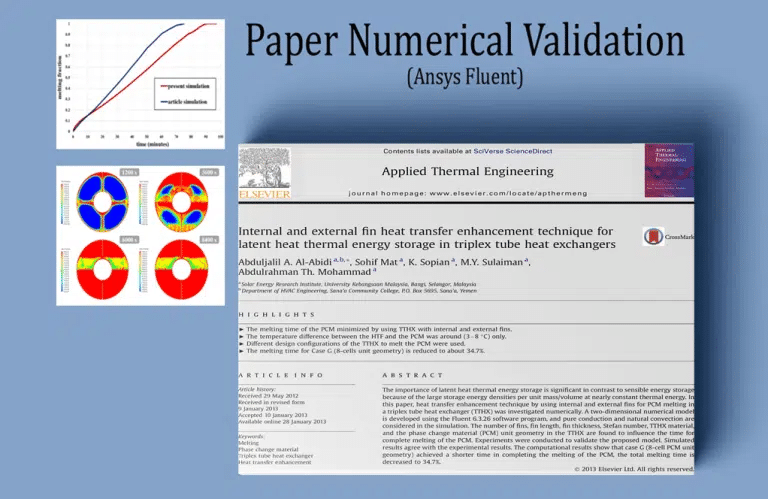
The current validation is based on the diagram in Figure 14 of the paper. This picture shows how the freezing fraction has changed over time. This image shows different geometric shapes based on how the fins of a heat exchanger are set up. In this simulation, cases A and B from Figure 2 of the paper examine two case studies. Based on the pictures that were made, we can say that after a certain amount of time, almost all of the PCM material turns into a liquid phase.
At the end of the solution process, both models (the one with fins and the one without) have two-dimensional outlines that show the temperature and the amount of liquid. As the phase-change material’s temperature goes up, the amount of liquid volume fraction goes up.
Enhance heat transfer for PCM melting in a triplex tube with internal-external fins.
ANSYS Fluent software simulates melting PCM in a triplex tube with an internal-external fin. The data from the reference article [Enhance heat transfer for PCM melting in a triplex tube with internal-external fins] was used for the simulation. The results are checked against the data in the paper to ensure they are correct.
This simulation is only done in two dimensions, so only a small piece of the pipe with a hole in it is modeled. The pipe has four rows of fins on the outside connected to the inner diameter wall and four on the inside connected to the outer diameter wall. Both the inner and outer walls of the pipe, as well as their fins, are made of copper.
The RT-82 inside the tube is a phase-changing material. At the end of the exercise, the results of this work are compared to the results in the paper to ensure they are the same. The graphs in Figure 7 and Figure 13 of the paper are used for this. Figure 7 shows how the average temperature of phase-change materials changes over time, and Figure 13 shows how the liquid mass fraction changes over time due to the melting process.
This work is about the state of the paper in which the inner and outer fins affect the phase change materials at the same time. Also, two-dimensional contours based on pressure, temperature, and the melting process’s liquid mass fraction are acquired after the solution process. Because the simulation process changes over time, the results of the present work are taken from different points in the simulation output.
PCM in Shell and Tube Finned Heat Exchanger
ANSYS Fluent software models how a Phase Change Material (PCM) works inside a shell and tube-finned heat exchanger. We do this CFD job and use CFD analysis to look into it. PCM can store thermal energy during the phase change (from solid to liquid or vice versa). When the phase changes from solid to liquid, it takes heat from the environment, and when it changes from liquid to solid, it gives heat back to the environment.
The temperatures at which these phase-change materials melt, or freeze are different and used in cooling and heating devices. For example, on a hot day, these materials absorb heat from the environment as latent heat and melt. This heat was returned to the environment when the phase changed, and the materials froze.
The shell looks like a cylinder tank with phase change materials (PCMs) spread out evenly inside the tank. Since the PCMs of this model are based on the change between the liquid and solid phases, the solidification and melting model was used for this exercise.
Because the modeling process takes time, it is done in 880 s intervals with a time step of 1200 s. At the end of the solution process, the temperature and mass fraction of the liquid are shown as two-dimensional curves. These edges are found during the last second of the modeling process, the 1200s. The outlines show that as time has passed and the PCM material has melted, the heat has been transferred well, and the temperature in the middle of the tubes has gone up.
Solidification and Melting of PCM on a Corrugated Tube
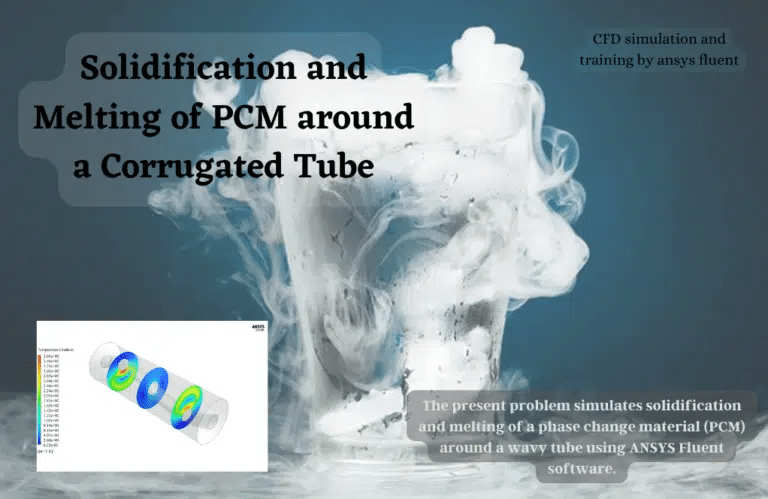
When these materials change from solid to liquid or liquid to solid, they store thermal energy. When they change from solid to liquid, they absorb heat from their surroundings, which cools the space around them, and when they change from liquid to solid, they return heat to their surroundings, which warms the space around them.
In this example, paraffin is the phase-change material that is looked at. After simulating, the temperature, the temperature difference, the pressure, and the amount of liquid are all plotted. Since the simulation is not done steadily, the current results come from the 7000s of the exercise.
The results show that PCM acts the same way regardless of its temperature. The heat from the inner tube raises the temperature of the PCM. As a result, the PCM goes through a phase change by releasing its latent heat. When the temperature increases, PCM turns from a solid to a liquid.
Phase Change Material (PCM) in a Finned Tube
This issue is about using ANSYS Fluent software to simulate PCM. We do this CFD job and use CFD analysis to look into it. During the phase change process, PCM stores thermal energy. When it goes from solid to liquid, it takes heat from the environment; when it goes from liquid to solid, it gives heat back to the environment.
PCMs have a wide range of melting (Liquidus) or freezing (solidus) temperatures, so they are used in cooling and heating systems. These materials receive solar energy as latent heat and melt on warm days. Then, they return the heat to the environment when it gets cold at night by changing the phase, solidification, and melting process.
PCMs are built into a three-layer tube heat exchanger as a latent heat storage tank. The inner tube body and ends are made of copper, which has good thermal conductivity. The fluid in the inner tube is liquid silicone, and the PCM is Erythritol. For CFD modeling, a Solidification and Melting module is used. This is because the PCMs of this model are based on the change in phase between the solid and liquid phases. The process of simulating is done over 12,000 seconds.
This study looks into the fluid and temperature behavior of phase-change materials and the amount of fluid in a solid-liquid mixture based on the fins’ size and shape and the fluid’s features inside the tube. The flow of liquids coming in has a speed of 1 m/s and a temperature of 343.15 kelvin. The software thinks of outer walls as having a heat flow of 0 and inner walls as coupled walls.
At the end of the solution process, the temperature and mass fraction of the liquid are shown as two-dimensional curves. The 1200s, the last second of the simulation process, is used to get these outlines. The outlines show that, as time has passed and the PCM material has melted, heat has been transferred well, and the temperature in the middle of the tubes has gone up.
PCM Industrial Companies
Several companies globally specialize in Phase Change Material (PCM) technology. These companies supply PCM products for various applications, including energy storage, building insulation, and thermal management. Here are a few examples:
Phase Change Energy Solutions
This company is a global leader in developing and deploying innovative energy efficiency and thermal storage solutions that harness the power of phase change materials.
Pure Temp
PureTemp is a leading manufacturer of PCM solutions. They offer various biodegradable PCM products with different phase change temperatures.
Climate Sweden AB
Climator Sweden AB is a pioneer in PCM technology. They have developed a range of PCM-based products for thermal energy storage, including Climator’s patented ThermoDeck for building climate control.
PCM Products
PCM Products is a UK-based company that develops and applies phase change materials for heating and cooling applications.
Rubitherm Technologies GmbH
Rubitherm Technologies GmbH is a German company offering various organic and inorganic PCM products for various applications.
These companies are at the forefront of PCM technology, providing innovative solutions for various industrial applications.
MR CFD Industrial Experience in the Solidification & Melting (PCM) Field
Some examples of Solidification & Melting industrial projects recently simulated and analyzed by MR CFD in cooperation with related companies are visible via the MR CFD website.
You may find the Learning Products in the Solidification & Melting CFD simulation category in Training Shop. You can also benefit from the Solidification & Melting Training Package, which is appropriate for Beginner, Intermediate, and Advanced users of ANSYS Fluent. Also, MR CFD is presenting the most comprehensive Solidification & Melting Training Course for all ANSYS Fluent users from Beginner to Experts.
Our services are not limited to the mentioned subjects. The MR CFD is ready to undertake different and challenging projects in the Solidification & Melting modeling field ordered by our customers. We even carry out CFD simulations for any abstract or concept Design you have to turn them into reality and even help you reach the best strategy for what you may have imagined. You can benefit from MR CFD expert Consultation for free and then Outsource your Industrial and Academic CFD project to be simulated and trained.
By outsourcing your Project to MR CFD as a CFD simulation consultant, you will not only receive the related Project’s resource files (Geometry, Mesh, Case & Data, …), but you will also be provided with an extensive tutorial video demonstrating how you can create the geometry, mesh, and define the needed settings (preprocessing, processing, and postprocessing) in the ANSYS Fluent software. Additionally, post-technical support is available to clarify issues and ambiguities.
