Aerospike CFD Simulation Considering Shock Wave
$100.00 $50.00 Student Discount
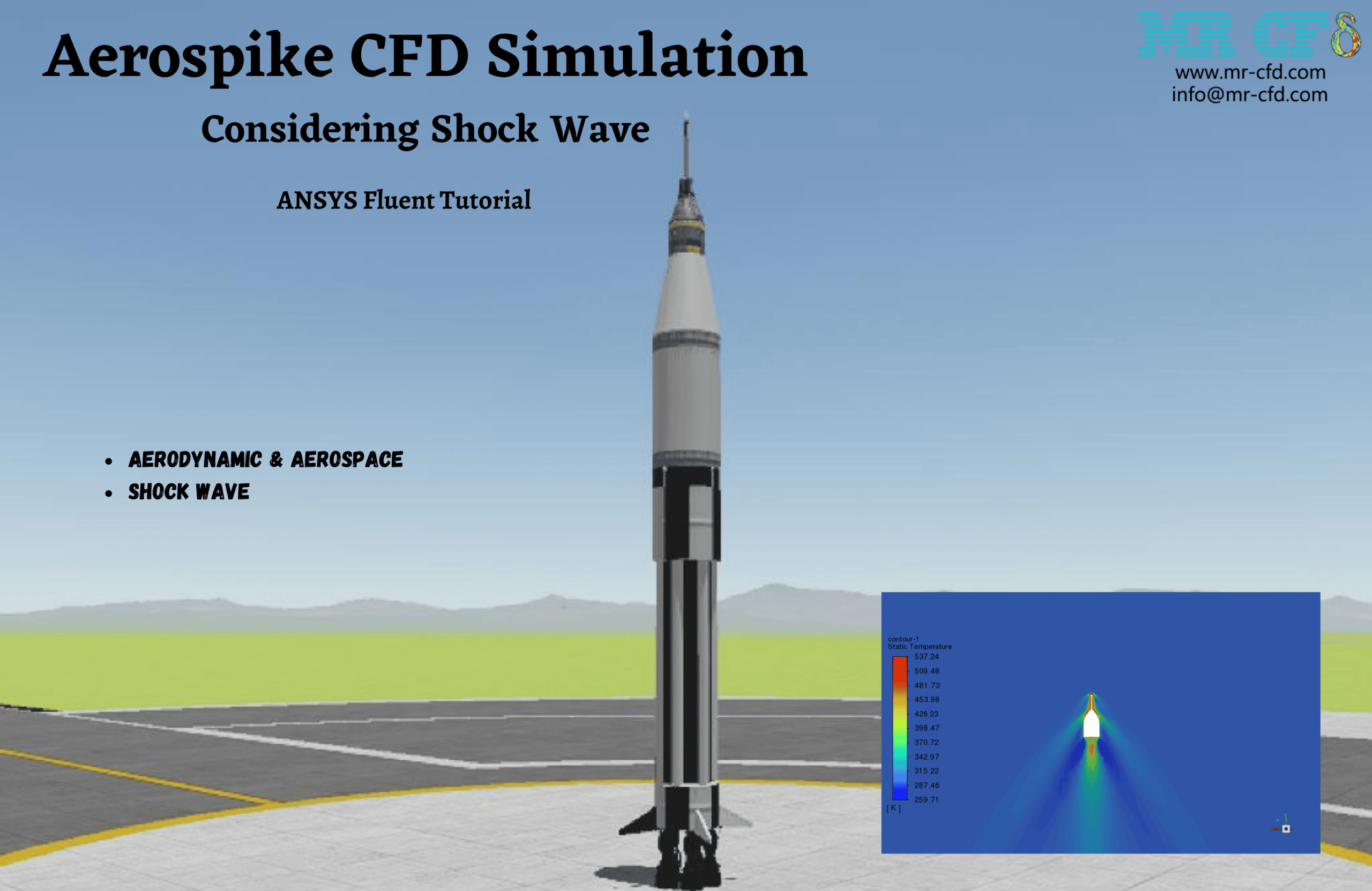
- The problem numerically simulates an Aerospike Considering Shock Wave using ANSYS Fluent software.
- We design the 3-D model by the Design Modeler software.
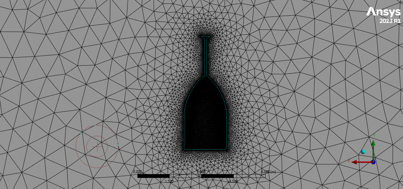
- Mesh grid is generated using ANSYS Meshing, and the element number equals 153,987.
- k-Omega SST turbulence model is used to capture the shock wave.
To Order Your Project or benefit from a CFD consultation, contact our experts via email (info@mr-cfd.com), online support tab, or WhatsApp at +44 7443 197273.
There are some Free Products to check our service quality.
If you want the training video in another language instead of English, ask it via info@mr-cfd.com after you buy the product.
Description
Project Description
In this project, we simulated an aerospike using ANSYS Fluent software. This simulation aims to model a cone with an aerospike antenna to how the aerospike antenna will affect shaping shock waves in distance from the nose cone and reducing drag.
A drag-reducing aerospike is a device used to reduce the forebody pressure aerodynamic drag of blunt bodies at supersonic speeds. The aerospike creates a detached shock ahead of the body. A zone of recirculating flow occurs between the shock and the forebody, Which acts like a more streamlined forebody profile, reducing the drag.
The geometry is designed in ANSYS Design Modeler software. The meshing of this present model has been generated by ANSYS Meshing software. The mesh grid is unstructured, and the total cell number is 153,987. the figure below shows an overview of the performed mesh.
Methodology: Aerospike CFD Simulation Considering Shock Wave
k-omega SST model with the speed of 2.5 Mach has been considered for this simulation.
Results
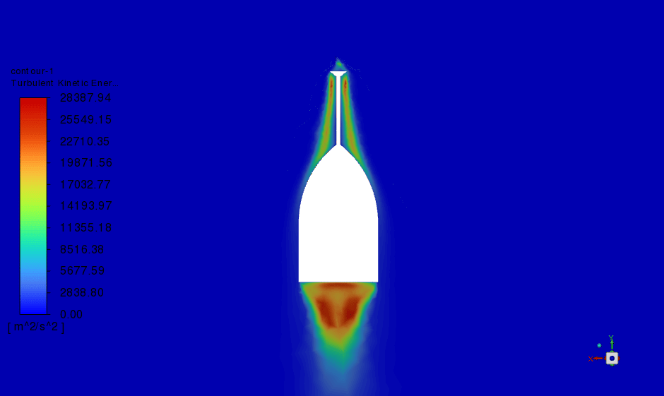
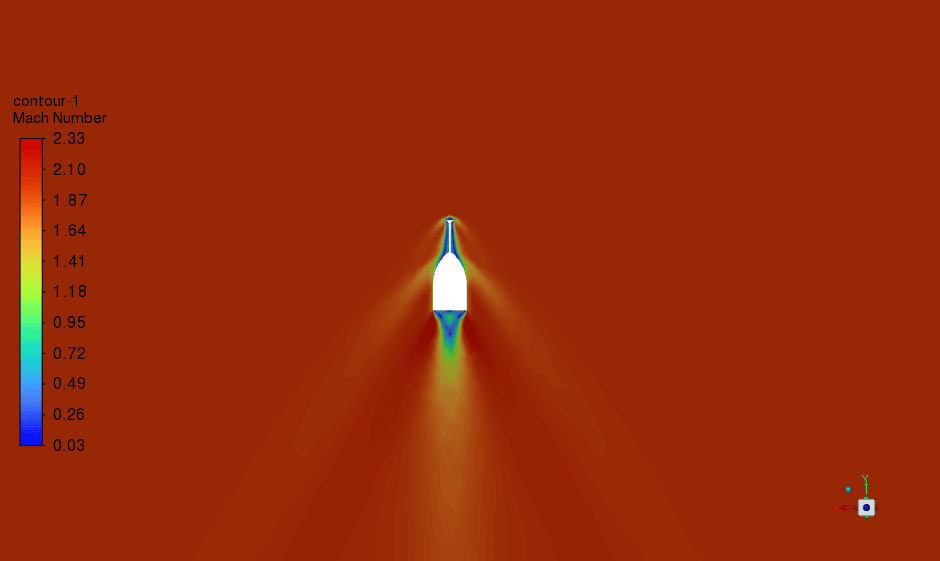
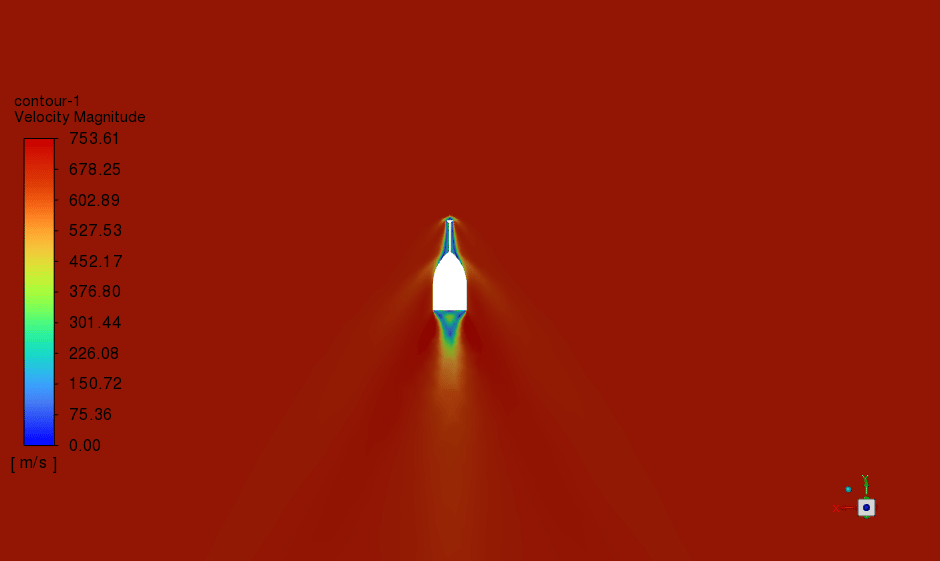
At the end of the solution process, two-dimensional velocity and animation are obtained. The result is showing aerospike resulted from much thinner and weaker Oblique Shock and far from the cone.
This affects drag reduction because the primary shock wave pressure gradient is far from the body. Also, a small separation wave takes place on the cone itself. Also, reattachment of separate waves and oblique shock happens at a distance from the main body and reduces aerothermodynamics’ efficiency.



Percy Wisozk –
I found the explanation on how the aerospike influences shock wave behavior and drag reduction fascinating. The use of the k-omega SST model seems ideal for such high-speed aerodynamics. Can you clarify if the reattachment of separate waves leads to any potential stability issues or other complexities during the simulation?
MR CFD Support –
In the high-speed aerodynamics simulation of the aerospike, the reattachment of separated waves can introduce complexities. However, these instances are accounted for in the simulation setup to accurately reflect their influence on the aerospike’s performance. The simulation ensures that despite these complexities, the aerospike functions as intended, reducing drag and altering shockwave characteristics without leading to significant stability issues. The results are designed to provide insights into the aerodynamic behavior of the aerospike, with a focus on efficiency and the minimization of potential stability problems.
Pamela Mayert –
I’m astounded by the detailed modeling of the aersopike and how the shock waves form around it. The engineering implications are fascinating and pivotal for advancements in aerodynamics. The CFD simulation results must be impressive to inspect,
MR CFD Support –
Thank you so much for your kind words! We’re thrilled that you found the Aerospike CFD simulation and its results both astounding and beneficial for aerodynamic research. It’s always rewarding to hear positive feedback from our customers on the intricate work involved in these simulations. If you ever have any questions or need further assistance, we’re here to help!
Mr. Skylar Bernhard DDS –
Very pleased with the aerospike simulation results! It’s quite fascinating to see how the shock wave is shaped and the drag is reduced effectively. The visualization of thin oblique shocks in the final result clearly reflects the technical sophistication of your CFD model.
MR CFD Support –
Thank you for your kind words! We are delighted to hear that you are satisfied with the simulation results and that the visualizations met your expectations. Our team strives to provide accurate and technical CFD models that offer insightful views into complex aerodynamics phenomena. We appreciate your feedback!
Miss Maxie Pfannerstill –
The detail on drag reduction via the aerospike was fascinating. Could you share how the separated waves are visualized in the simulation results?
MR CFD Support –
In the simulation results, the separated waves, also known as separation bubbles, are typically visualized using pressure contour maps or flow visualization techniques such as streamlines or pathlines. These methods allow you to see the recirculating flow between the shock wave and the forebody, highlighting where the flow separation and reattachment occur, indicating the presence of separate waves.
Neil Lynch II –
The report is very intriguing! Could you detail the drag reduction experienced with the aerospike compared to a traditional cone without an aerospike?
MR CFD Support –
The aerospike design helps to modify the shockwave patterns and usually reduces drag significantly compared to a blunt cone body. By creating a series of weaker, detached shocks, it decreases the high-pressure area in front of the cone, leading to reduced aerodynamic resistance. Exact drag reduction values depend on the specific design and simulation parameters, but the thinner and weaker oblique shocks created by the aerospike contribute to efficiency enhancements in supersonic flight conditions.
Dr. Gilberto Kemmer –
I was blown away by the results shown in the Aerospike CFD Simulation. The visuals were really clear for understanding the shock wave interactions. Impressive work!
MR CFD Support –
Thank you for your kind words! We’re thrilled to hear you found the simulation results and visuals clear and understandable. If you have any further questions or need more details, feel free to ask. We’re here to help!
Prof. Cornell Gottlieb –
Does the simulation cover how different velocities or Mach numbers might affect the efficacy of the aerospike?
MR CFD Support –
In this specific simulation, the aerospike was modeled at a supersonic speed of 2.5 Mach using the k-omega SST model. However, additional simulations at varying velocities and Mach numbers would be necessary to more comprehensively understand the effect of speed on the aerospike’s performance and drag reduction capabilities.
Magdalena Cummerata –
I am impressed by the simulation’s ability to create a more realistic forecast by considering the shock wave impact on aerodynamics. Can you share how the use of the k-omega SST model has influenced the accuracy of the simulation?
MR CFD Support –
Thank you for your kind words! The k-omega SST model is specifically designed to capture the effects of turbulence with high accuracy in boundary layers, which is essential in supersonic flow regimes. It helps to accurately predict the onset and the strength of shock waves and their interaction with the boundary layer. This, in turn, leads to precise calculations of drag forces acting on the aerospike-equipped nose cone and enables the simulation to effectively predict the drag reduction benefits.
Dejah Shanahan II –
I’m curious about how the aerospike impacts the overall efficiency of a vehicle traveling at supersonic speeds. Could you provide more insights about the improvements in aerodynamics or fuel efficiency that could result from this design?
MR CFD Support –
Absolutely! The aerospike design significantly impacts the efficiency of supersonic vehicles by reshaping the shock wave. The detached worry creates by the aerospike results in a reduced drag coefficient when compared to traditional blunt body designs. This leads to lower aerodynamic resistance, which means the vehicle requires less thrust and fuel consumption to maintain supersonic speeds. The reduction in aerodynamic heating due to a weaker shock wave also contributes to the material integrity and overall safety of the design. It is a more streamlined way to manage high-speed flows, enhancing both aerodynamics and fuel efficiency.
Tate Morar –
I’m really impressed with how the aerospike antenna can affect the shaping of shock waves and reduce drag. Can I see videos of these simulations and results?
MR CFD Support –
Thank you for your interest and appreciation of our CFD simulation on an aerospike! You can definitely view the simulation results and animated visualizations. They showcase the formation of oblique shock waves and their interaction with the aerospike and cone. For access, you may check our website or the platform where you purchased the product. If you have any difficulty finding the animations or need further clarification, don’t hesitate to reach out to our support team for assistance.
Samson Williamson I –
The results of the aerospike simulation were super helpful for understanding shock waves. The animations made the concept much clearer. Great job on presenting complex data in an easy-to-digest format!
MR CFD Support –
Thank you for your kind words! We’re thrilled to hear that our aerospike simulation was able to clarify the concept of shock waves for you. Putting complex data into an understandable format is one of our key goals. We appreciate your feedback!
Kale Nienow –
The aerospike simulation looks remarkably effective for drag reduction at supersonic speeds. The visuals of the shock wave interactions are compelling and illustrate the concepts clearly.
MR CFD Support –
We appreciate your positive feedback on the aerospike CFD simulation! It’s great to hear that the results were clear and demonstrated the effectiveness of the aerospike design for reducing aerodynamic drag. Thanks for taking the time to review our product!