Arc Welding CFD Simulation, ANSYS Fluent
$180.00 $90.00 Student Discount
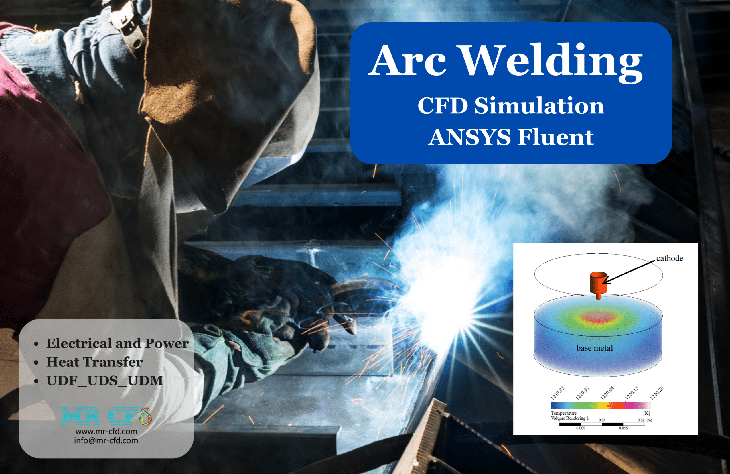
- In this project, an Arc Welding is modeled using ANSYS Fluent.
- A User-Defined Scalar (UDS) is added for calculating the electrical properties, and a User-Defined Function (UDF) is used for the computation of heat release from the electric field, which is added to the energy equation as a source term.
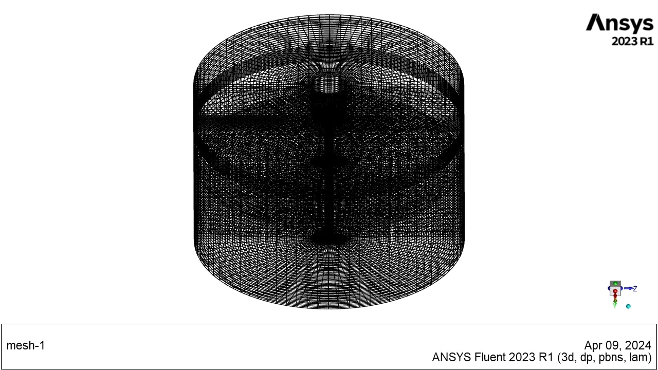
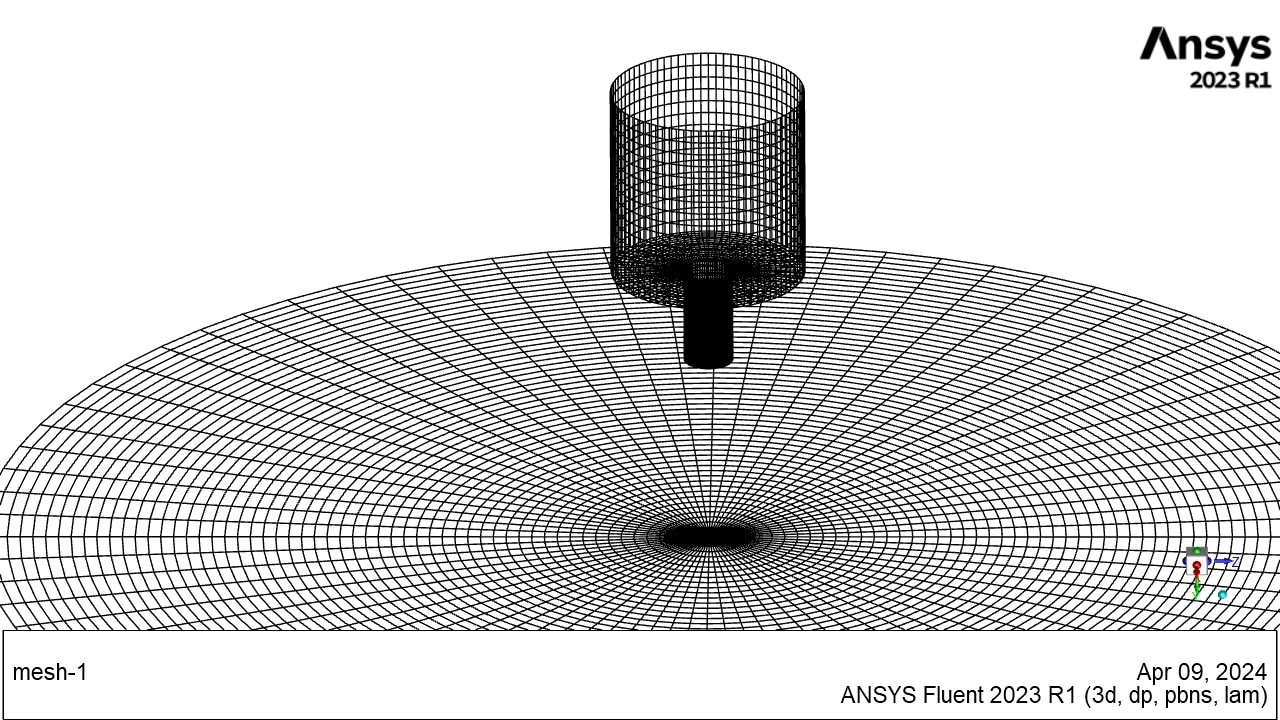
- The geometry was created in SpaceClaim, and a mesh consisting of 335,560 elements was generated using ANSYS Meshing.
To Order Your Project or benefit from a CFD consultation, contact our experts via email (info@mr-cfd.com), online support tab, or WhatsApp at +44 7443 197273.
There are some Free Products to check our service quality.
If you want the training video in another language instead of English, ask it via info@mr-cfd.com after you buy the product.
Description
Description
Arc welding is a welding process that utilizes electricity to generate sufficient heat to melt and fuse metal together. Examining this process in detail reveals that the high voltage between the electrode (cathode) and the base metal causes the air or surrounding medium to become ionized, establishing an electric current. This working electricity significantly increases the air temperature, which further ionizes the air. The ionized air facilitates the electric current flow between the electrode and base metal, leading to heat generation. This cycle creates a stable process that maintains a high-temperature region for metal melting.
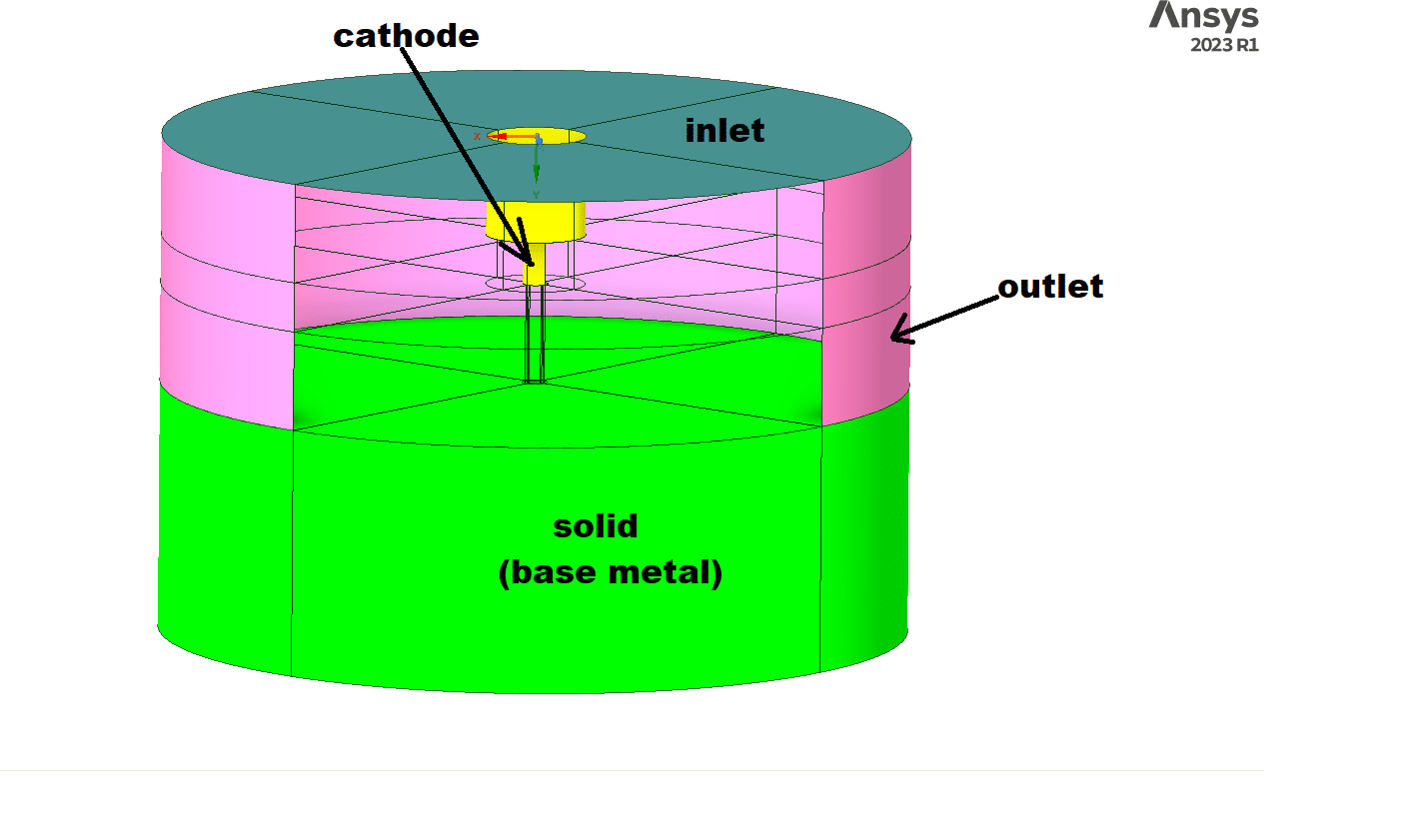
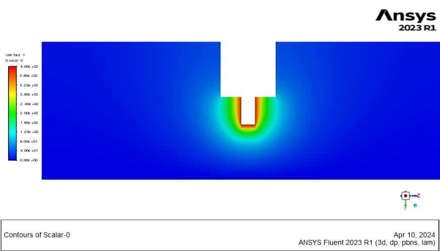
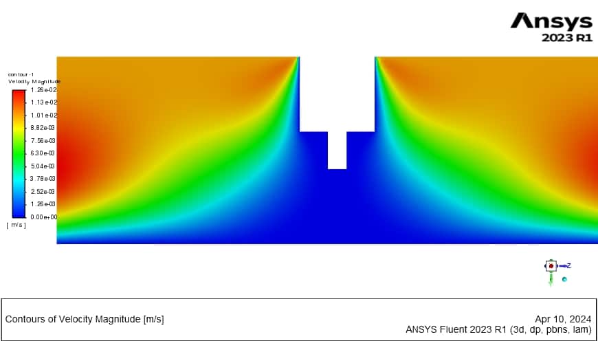
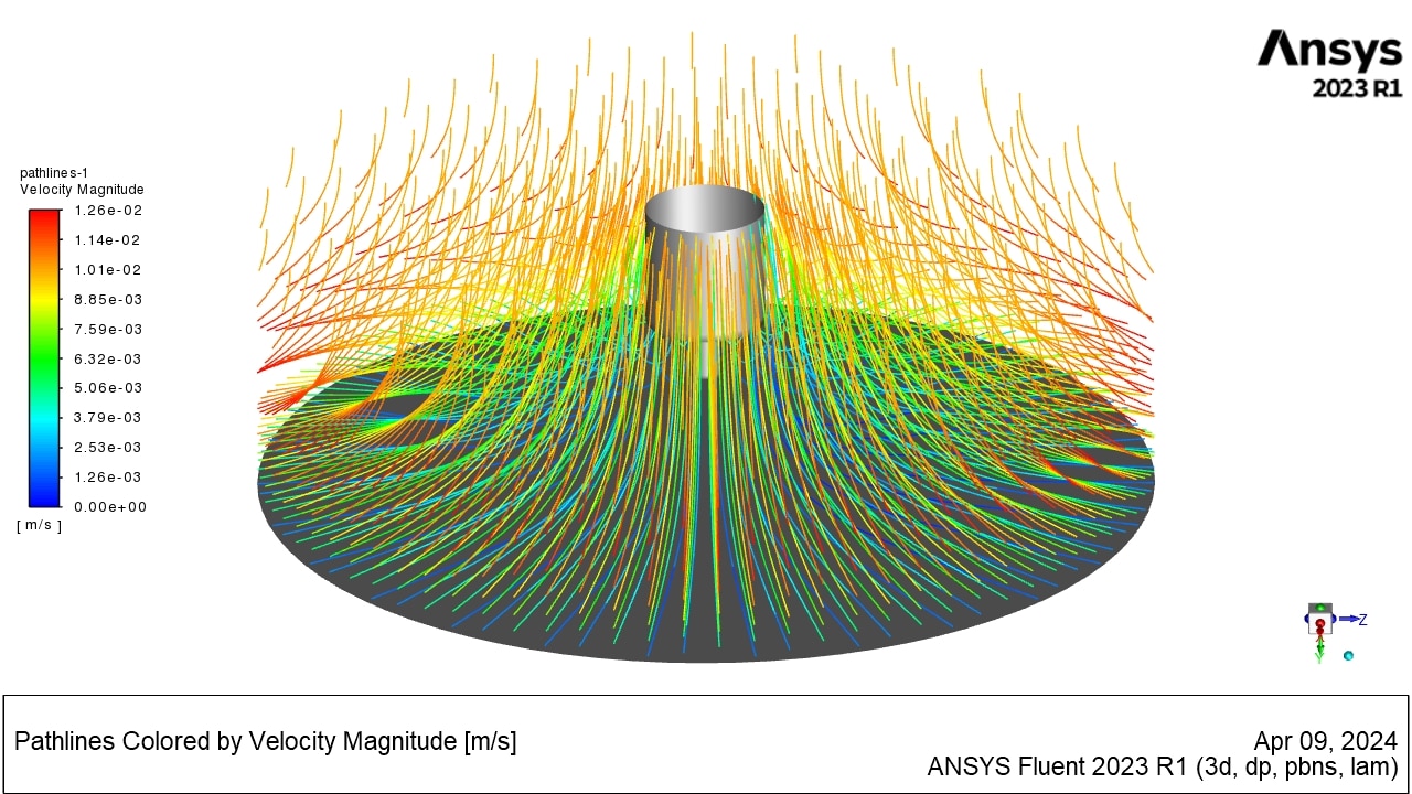
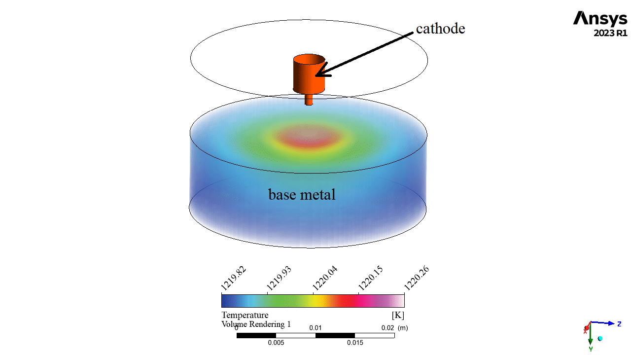
In this simulation, the cathode is positioned 4 mm away from the base metal. The cathode voltage is set to 400 V, while the base metal is at 0 V, serving as the ground electrical potential. The inlet air enters from the top boundary at a velocity of 0.01 m/s and a temperature of 1000 K. The temperature of the cathode wall is maintained at 2000 K. Also ionized air electrical diffusion coefficient is considered to be 0.005.
The geometry is designed in SpaceClaim® and meshed using ANSYS Meshing®. The Mesh type is structured with the element count being 335,560.
Methodology
In this simulation, the velocity is too low and the length scale is very small, so the problem is simulated as Laminar, and the energy equation is activated. To simulate electricity, we add a User-Defined Scalar (UDS). In this problem, the scalar represents voltage or electrical potential (V), and as we know, it does not have a mass flow flux. The steady-state transport equation of the scalar (V) with no source term and electrical potential flux formulation is presented below:
In this relation, k is the electrical diffusion coefficient of ionized air. The current flow density can be computed with the following formula:
In this formula, J represents the vector of current density. To couple with the energy equation, a source term is added to the energy equation as follows:
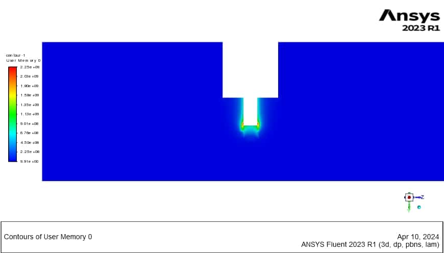
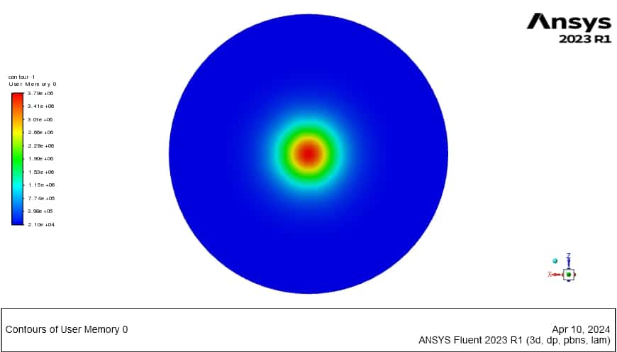
A User-Defined Function (UDF) is written and interpreted in Fluent based on the above formulation. We also use User-Defined Memory (UDM) to obtain the electrical heat release and current vector directly from the UDF code, which can be analyzed in the post-processing step.
Results
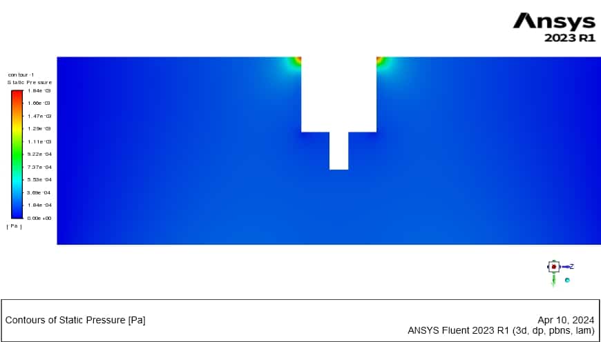
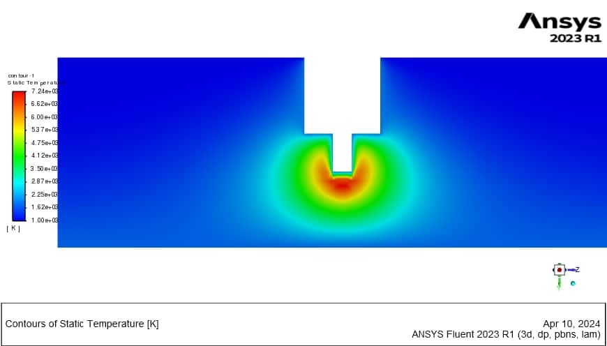
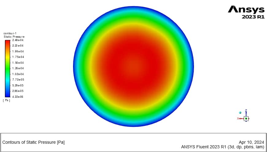
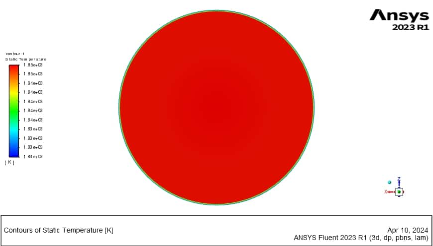
Contours of velocity and pressure around the cathode are presented in the axial plane. The temperature on the base metal surface indicates that the temperature can reach 1220 K, which is sufficient for metal melting; additionally, the maximum temperature in the domain is 7036 K, which is extremely high.
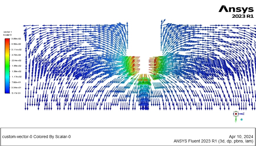
The electrical heat generation contour reveals that the maximum heat generation occurs around the cathode, as expected, due to the highest electrical potential gradient being in this area. The current vectors have also been extracted and are visible in the results. The current initiates at the cathode and moves toward the area with a lower electric potential (V).
Related products
-
HAWT (Horizontal Axis Wind Turbine) ANSYS Fluent CFD Simulation Training
Rated 4.00 out of 5$140.00$70.00 Student Discount


Reviews
There are no reviews yet.