Biomass Waste Incinerator CFD Simulation
$140.00 $70.00 Student Discount
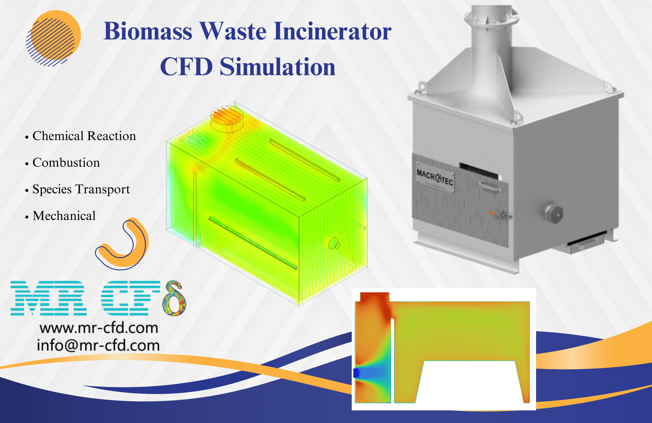
- This study uses ANSYS Fluent to simulate the combustion process of biomass waste in an industrial incinerator using Computational Fluid Dynamics (CFD).
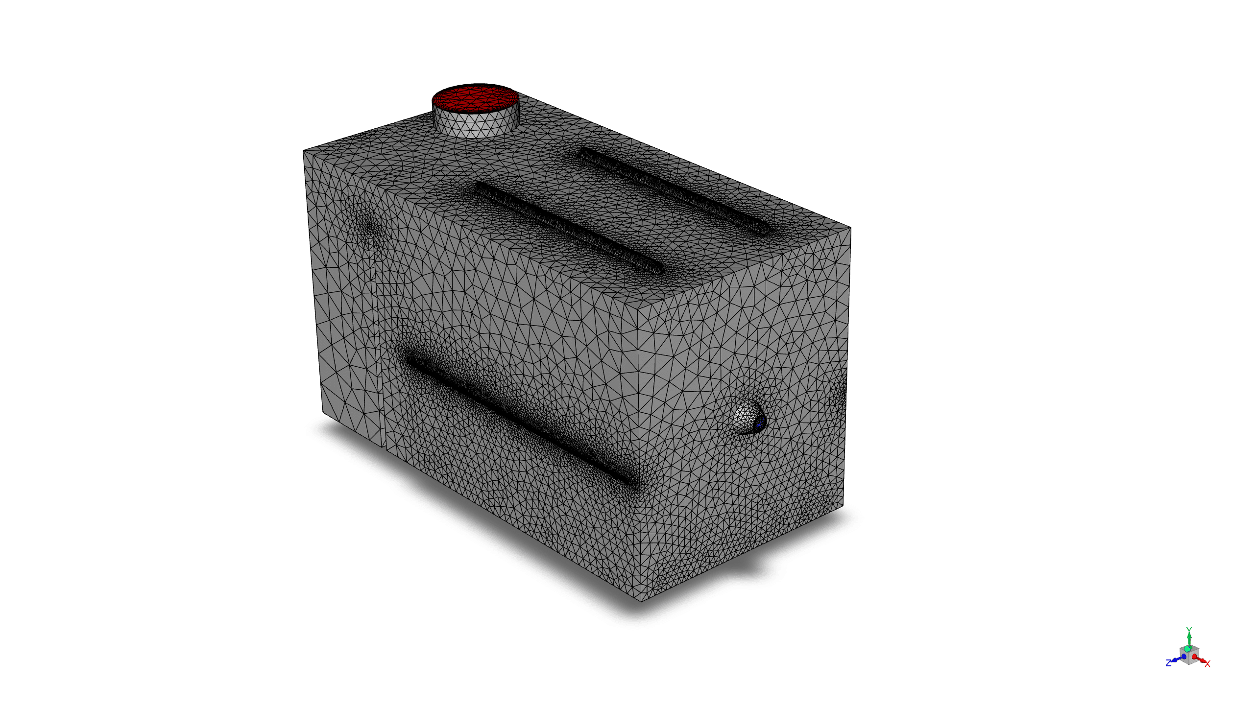
- The 3-D geometry is designed in ANSYS Design Modeler, and then is meshed using ANSYS Mesh, with the total 6,893,518 element number.
- The RNG k-ε model with standard wall functions is utilized for turbulence modeling.
- The energy equation is enabled to accurately model heat transfer within the system.
- The species transport model is employed to simulate the combustion process, with two primary reactions defined.
- The eddy-dissipation model is activated for turbulence-chemistry interaction.
To Order Your Project or benefit from a CFD consultation, contact our experts via email (info@mr-cfd.com), online support tab, or WhatsApp at +44 7443 197273.
There are some Free Products to check our service quality.
If you want the training video in another language instead of English, ask it via info@mr-cfd.com after you buy the product.
Description
Biomass Waste Incinerator CFD Simulation, ANSYS Fluent Tutorial
Introduction
This study investigates the combustion process of biomass waste in an industrial incinerator using Computational Fluid Dynamics (CFD) analysis. The simulation aims to understand the complex fluid dynamics, heat transfer, and chemical reactions within the incinerator, focusing on achieving uniform combustion on the rubbish surface. By employing advanced models for turbulence, species transport, and combustion, this research provides valuable insights into optimizing waste-to-energy processes and improving the efficiency of biomass incineration systems.
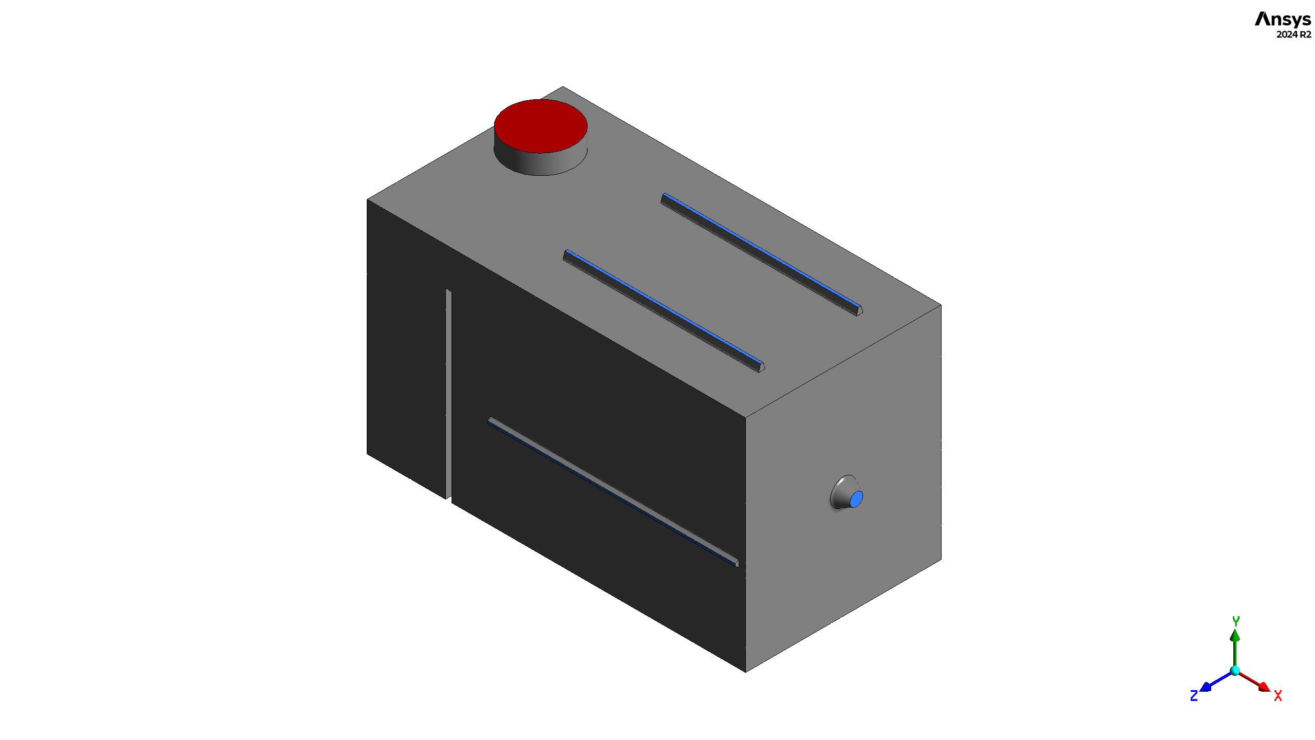
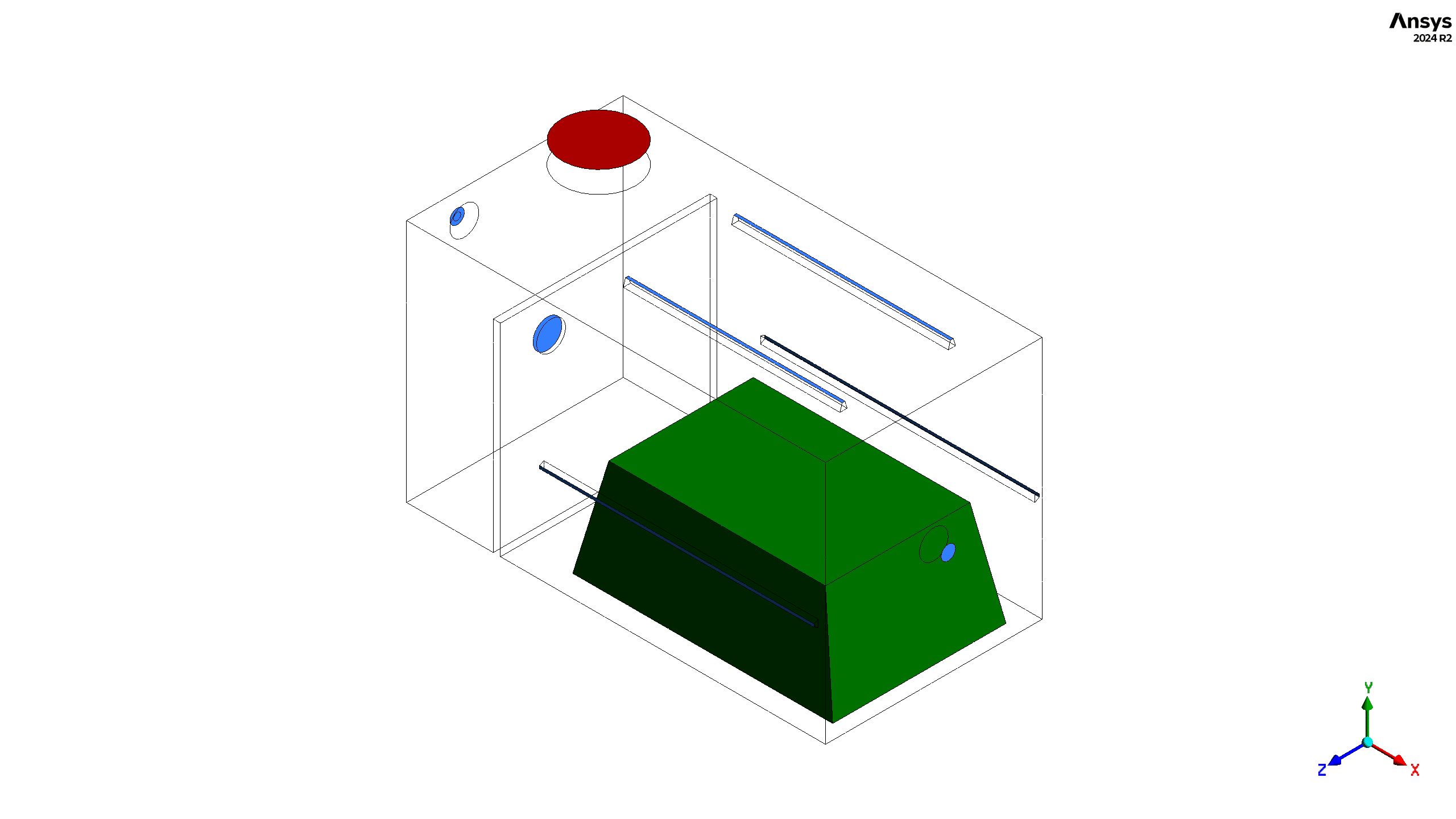
The CFD simulations were conducted using ANSYS Fluent software. The geometry designed in ANSYS Design Modeler represents an industrial incinerator with multiple air and fuel inlets and two exhaust gas outlets. The computational domain includes a trapezoidal waste pile, air inlets, fuel inlets, and a cooling system. Then the geometry is meshed using ANSYS Meshing software, while the total number of elements are 513233.
Methodology
The simulation was set up as a steady-state analysis using a pressure-based solver. The Realizable k-ε model with standard wall functions was utilized for turbulence modeling, accounting for the complex flow patterns within the incinerator.
The energy equation was enabled to accurately model heat transfer within the system, which is crucial for capturing the thermal behavior of the combustion process and its impact on the incinerator’s performance.
A species transport model was employed to simulate the combustion process, with two primary reactions defined: CH4 + O2 and H2 + O2. The eddy-dissipation model was activated for turbulence-chemistry interaction, simulating the fast chemistry regime typical in industrial combustion processes.
To represent the continuous generation of combustible gases from the waste, fixed source terms for CO and H2 mass fractions were applied at the rubbish surface boundary condition.
Results
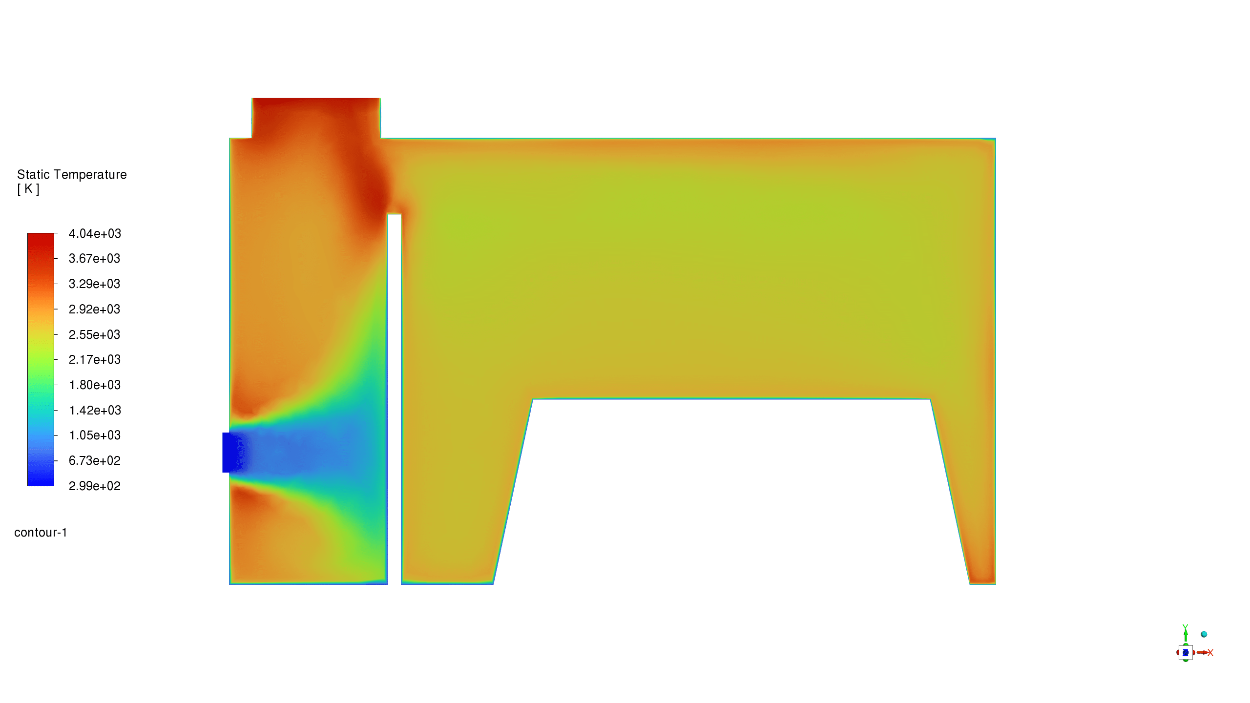
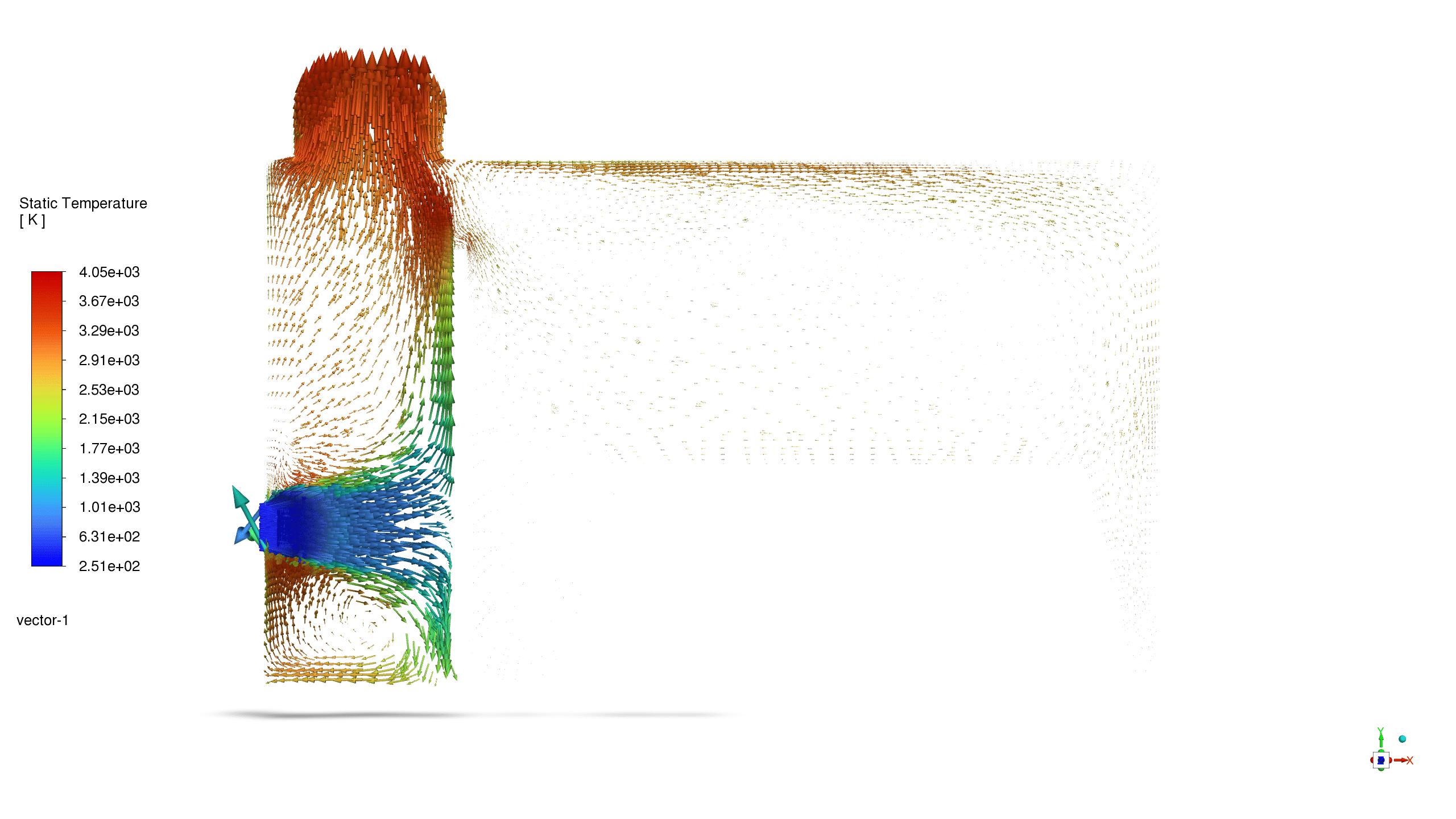
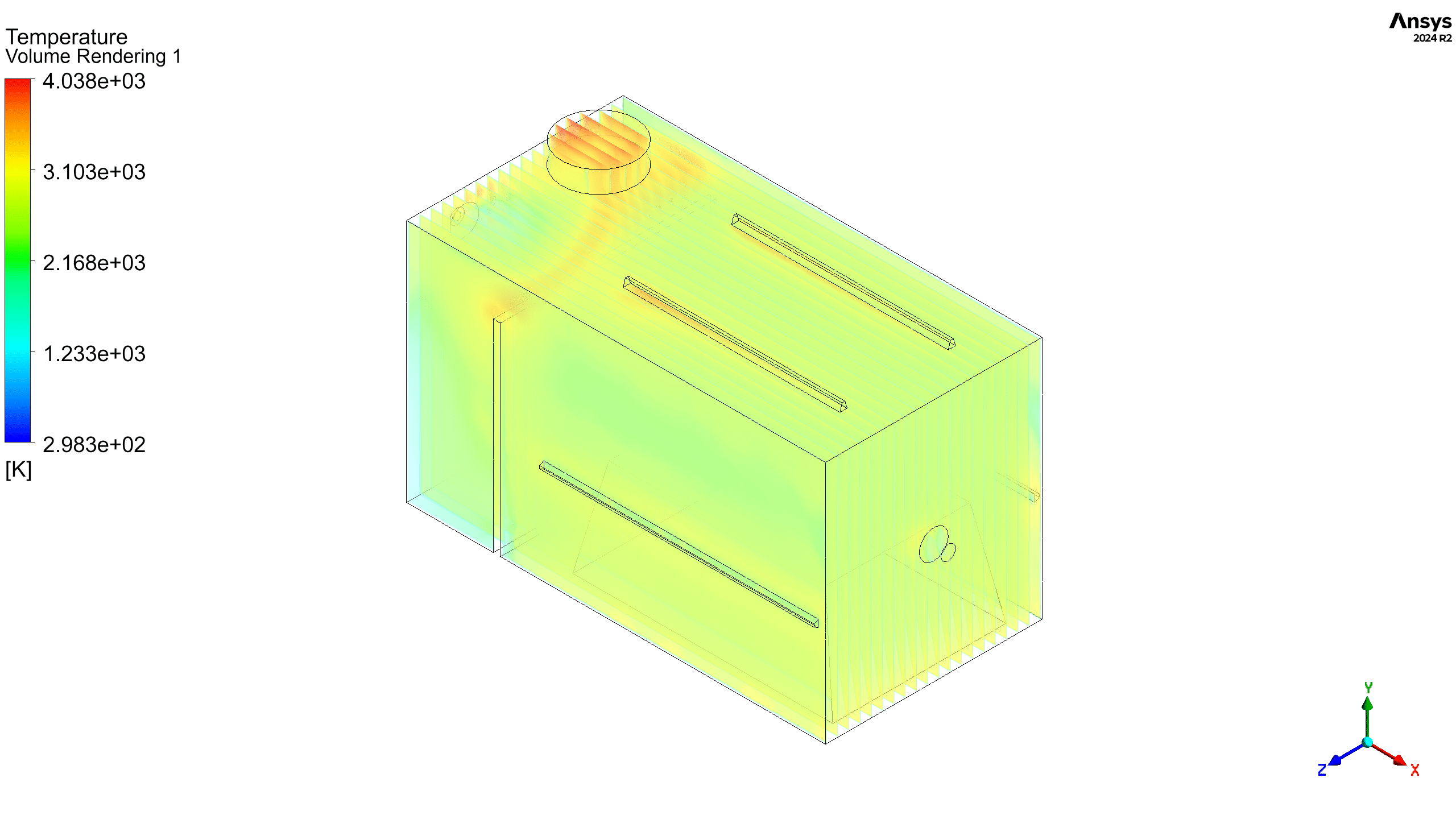
The simulation results show a significant temperature gradient within the incinerator. The outlet chamber temperature (4042.636 K) is considerably higher than the inlet temperature (300 K), indicating effective heat generation and transfer in the main combustion zone. The average temperature inside the incinerator zone is equal to 2619.4 K.
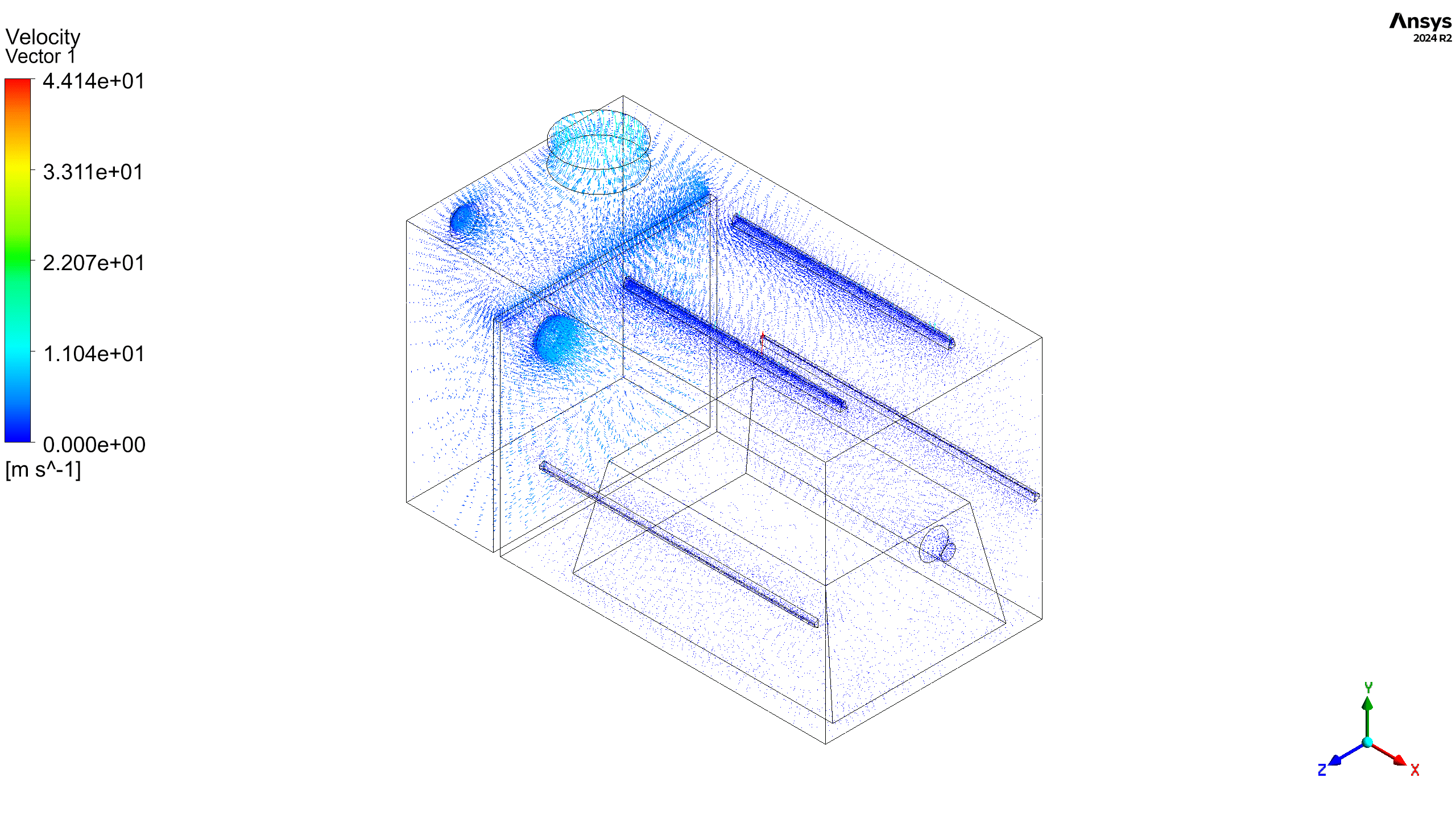
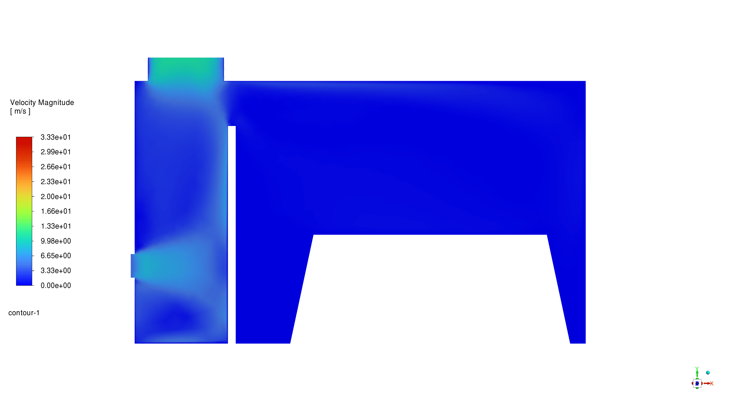
The velocity magnitude contours reveal complex flow patterns within the incinerator, with maximum velocities reaching 33.25 m/s. These flow patterns play a crucial role in mixing air and fuel, as well as distributing heat throughout the chamber.
The static temperature contours show peak temperatures exceeding 4000 K in the main combustion zone, indicating intense reactions. The temperature distribution on the waste surface varies, with higher temperatures observed near the fuel inlets and in regions of good air-fuel mixing.
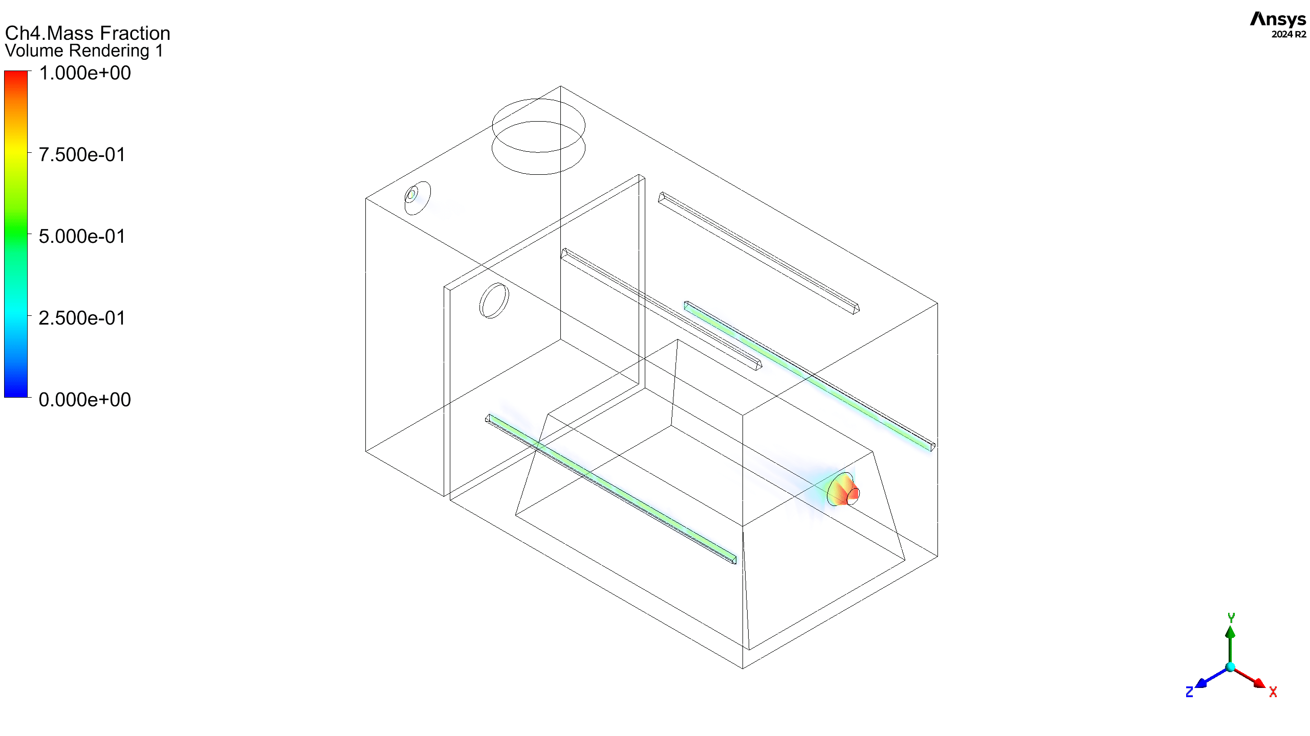
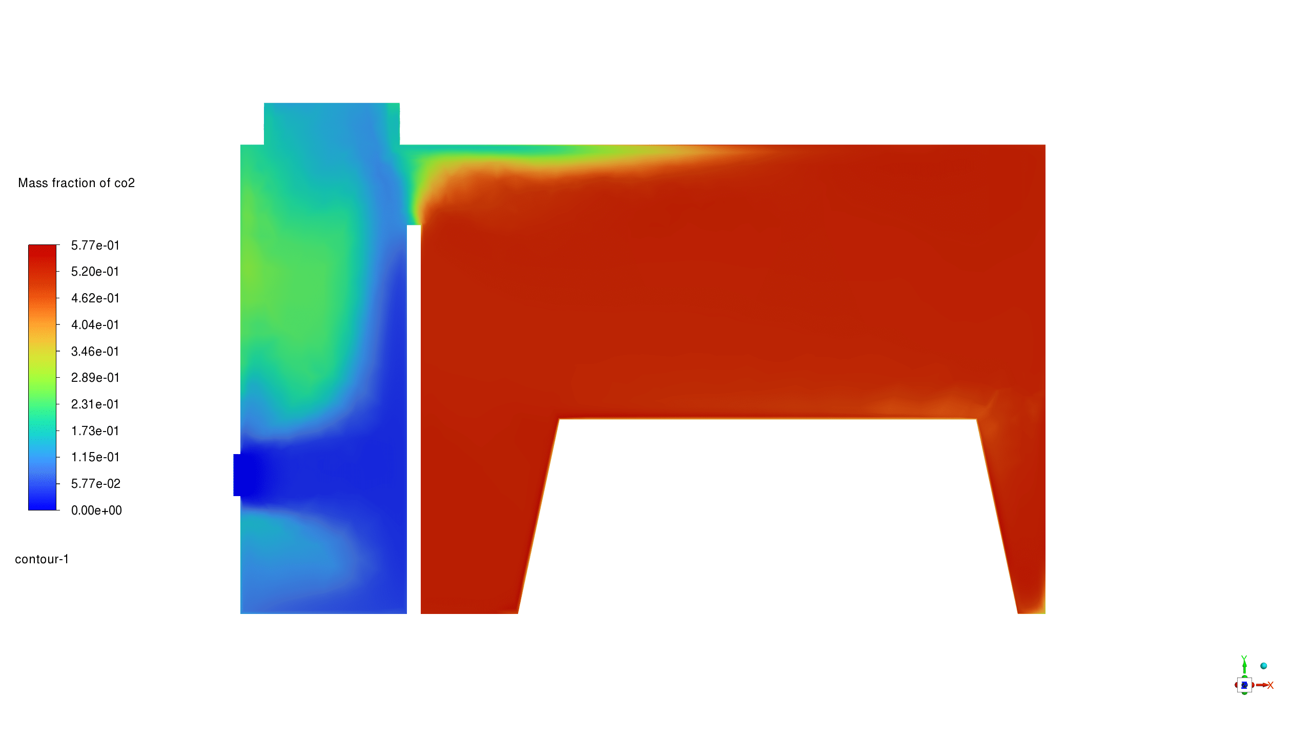
The mass fraction contours for CH4 and CO2 provide insights into the combustion process. High concentrations of CH4 are observed near the fuel inlets, while CO2 concentrations increase in the post-combustion zones, indicating the progress of the reaction.
The temperature-colored pathlines illustrate the complex three-dimensional flow within the incinerator. They show how the air and fuel streams interact, mix, and combust, creating recirculation zones that enhance mixing and promote more complete combustion.
The simulation results demonstrate the complex interplay between fluid flow, heat transfer, and chemical reactions in the biomass waste incinerator. The temperature gradients and species distributions highlight areas of efficient combustion as well as potential zones for optimization. The flow patterns revealed by velocity contours and pathlines suggest that careful design of inlet positions and flow rates is crucial for achieving uniform combustion on the rubbish surface.
While the current design shows good overall performance, there is potential for further optimization. Adjusting the positions and flow rates of air and fuel inlets could lead to more uniform temperature distribution on the waste surface, potentially improving combustion efficiency and reducing emissions.



Reviews
There are no reviews yet.