Blade Film Cooling CFD Simulation, ANSYS Fluent Training
$100.00 $50.00 Student Discount
- The problem numerically simulates the Blade Film Cooling using ANSYS Fluent software.
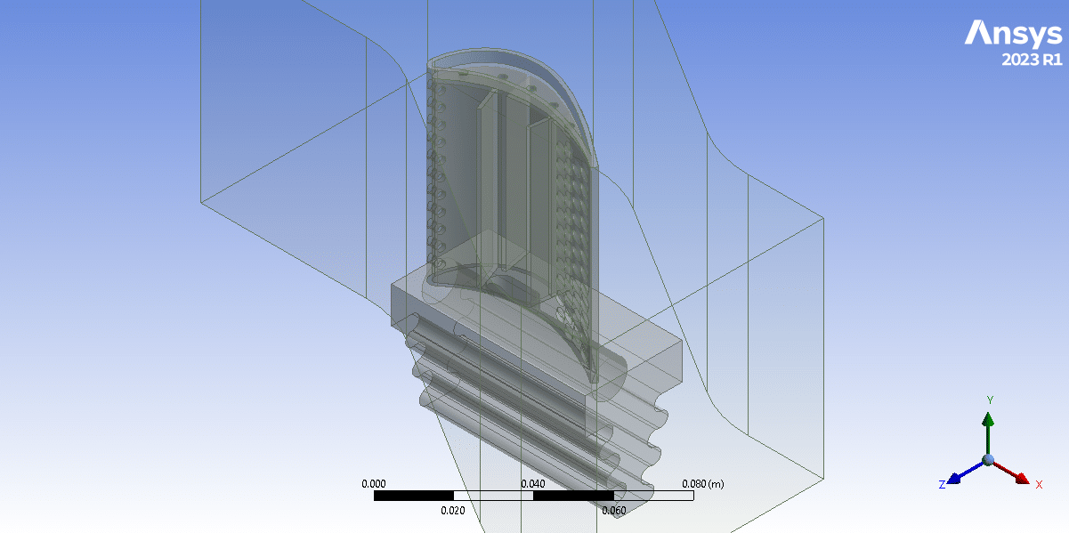
- The 3-D geometry is designed in Design Modeler software.
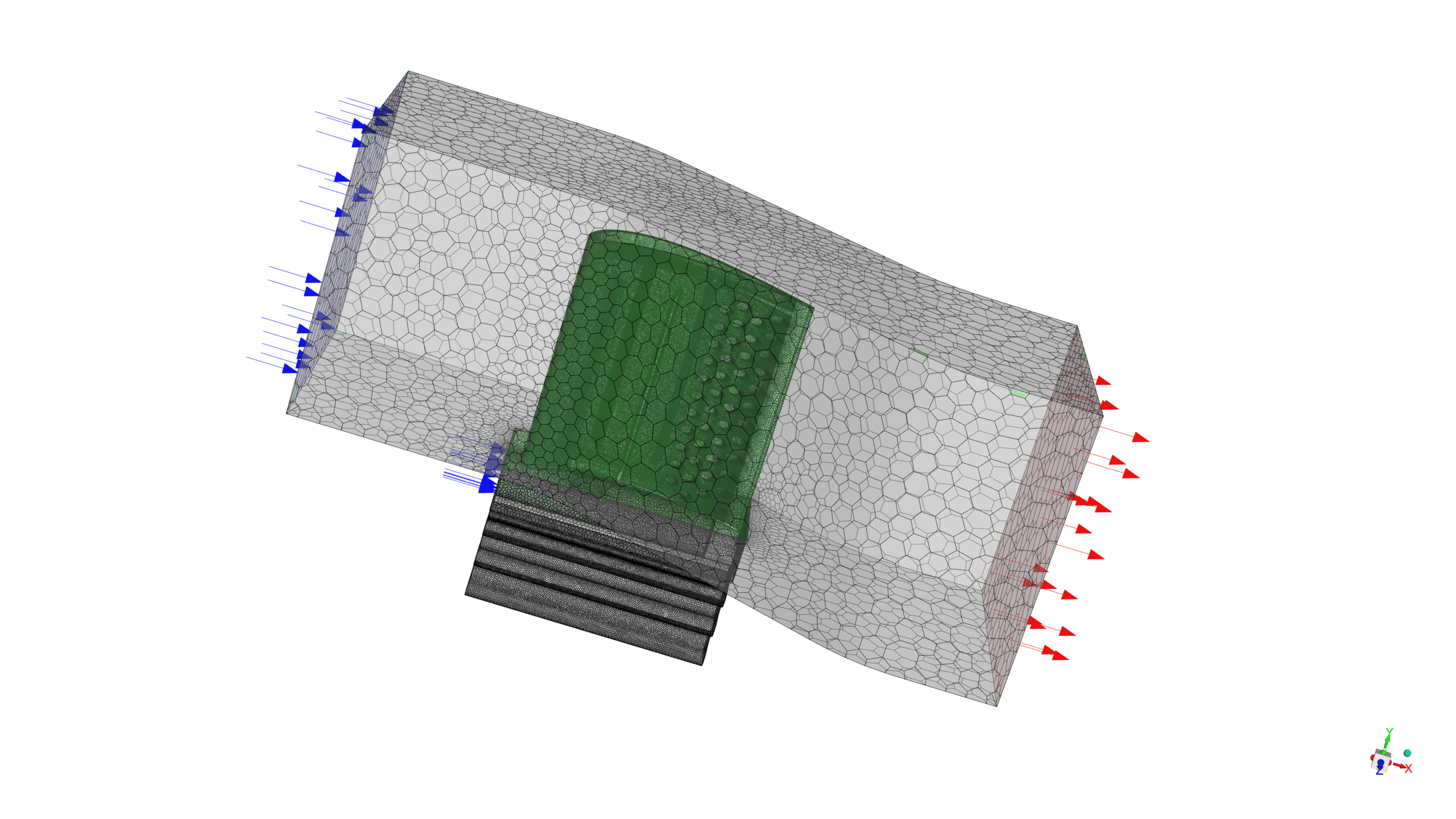
- We used polyhedra mesh type in ANSYS Fluent , with 2,697,514 elements.
- We use the K-Omega SST model to simulate turbulence.
To Order Your Project or benefit from a CFD consultation, contact our experts via email (info@mr-cfd.com), online support tab, or WhatsApp at +44 7443 197273.
There are some Free Products to check our service quality.
If you want the training video in another language instead of English, ask it via info@mr-cfd.com after you buy the product.
Description
Introduction
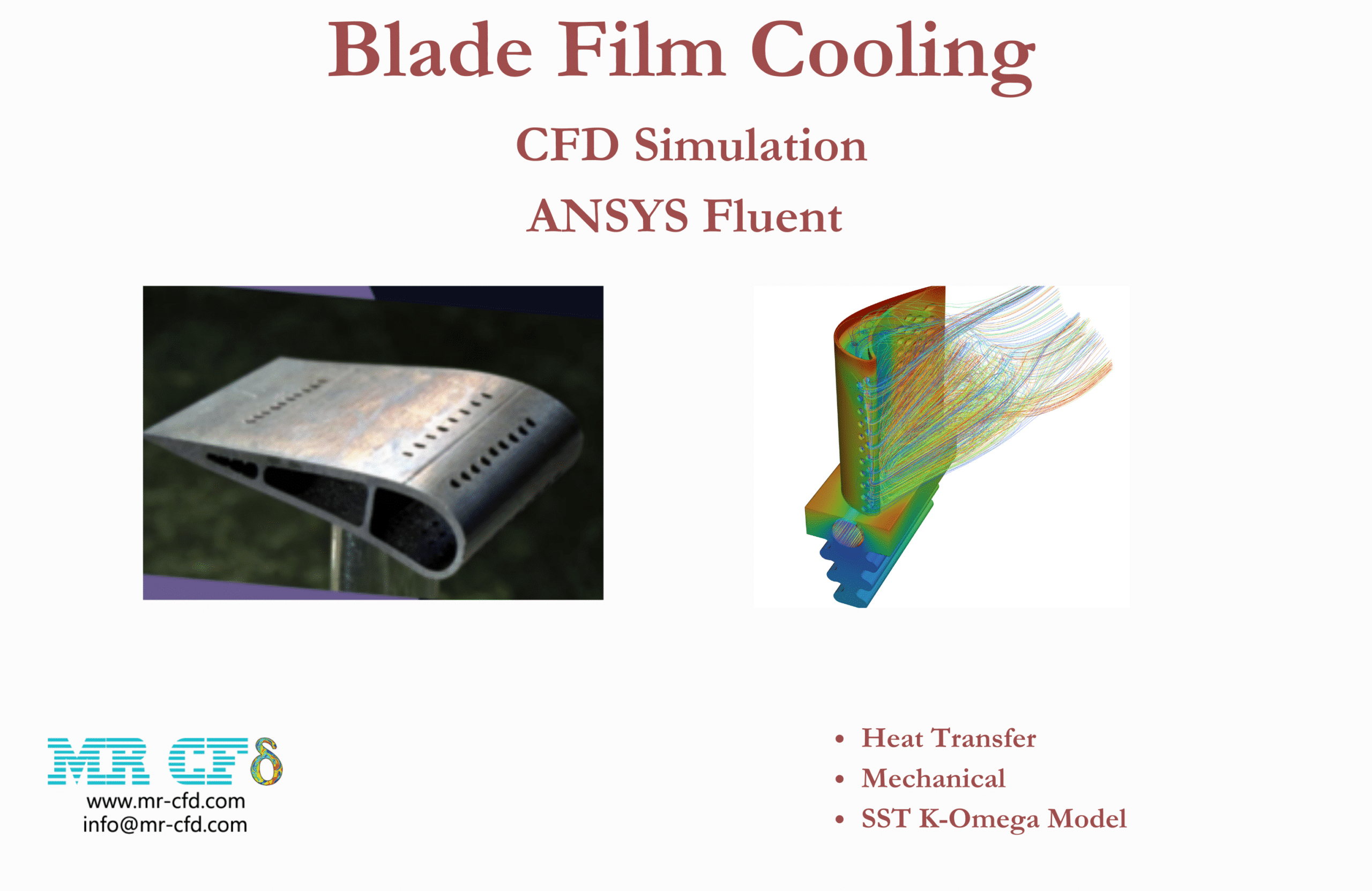
Blade film cooling is used in gas turbines to protect them from the high temperature generated after the combustion chamber. This method involves an injection of a layer of cool air film around the blade and establishes a thermal cover; this cool air usually supplies from the compressor section.
This cool air is directed with small tubes and holes on the compressor stage to the surface of the blades in the turbine stage via small holes and slats.
Several blade film techniques are used in gas turbines; the most common types are transpiration, impingement, and effusion. Transpiration cooling involves injecting cool air through small holes in the blade surface, which then flows through the porous material of the blade to the hot side.
Impingement cooling involves directing cool air onto the blade surface, impinges on the surface, and creates a cooling effect. Effusion cooling involves injecting cool air through a series of small holes or slots in the blade surface, forming a thin film over the blade surface.
One of the main challenges is the design of the cooling holes. The holes’ size, shape, and orientation can significantly affect the cooling effectiveness of the film cooling technique. Also, the distance between the cooling holes, the number of holes, and the angle of the holes affect the cooling effect. Another challenge is the interaction between the cooling air and the hot gases.
The hot gases can entrust the cooling air, which reduces the cooling effectiveness of the cooling film technique. The hot gases’ turbulence can also affect the cooling effect. It disrupts the excellent air layer and reduces the cooling effectiveness.
Blade Film Cooling CFD Simulation Methodology
We used a turbine blade geometry with film cooling holes and investigated the cooling effect on the blade solid geometry. We created the geometry in Design Modeler and meshed it in ANSYS Meshing software. Then we converted the mesh into polyhedra type in ANSYS Fluent , with 2,697,514 elements. The fluid and solid structure wall is coupled, and the flow is solved with the k-omega SST model.”
Conclusion
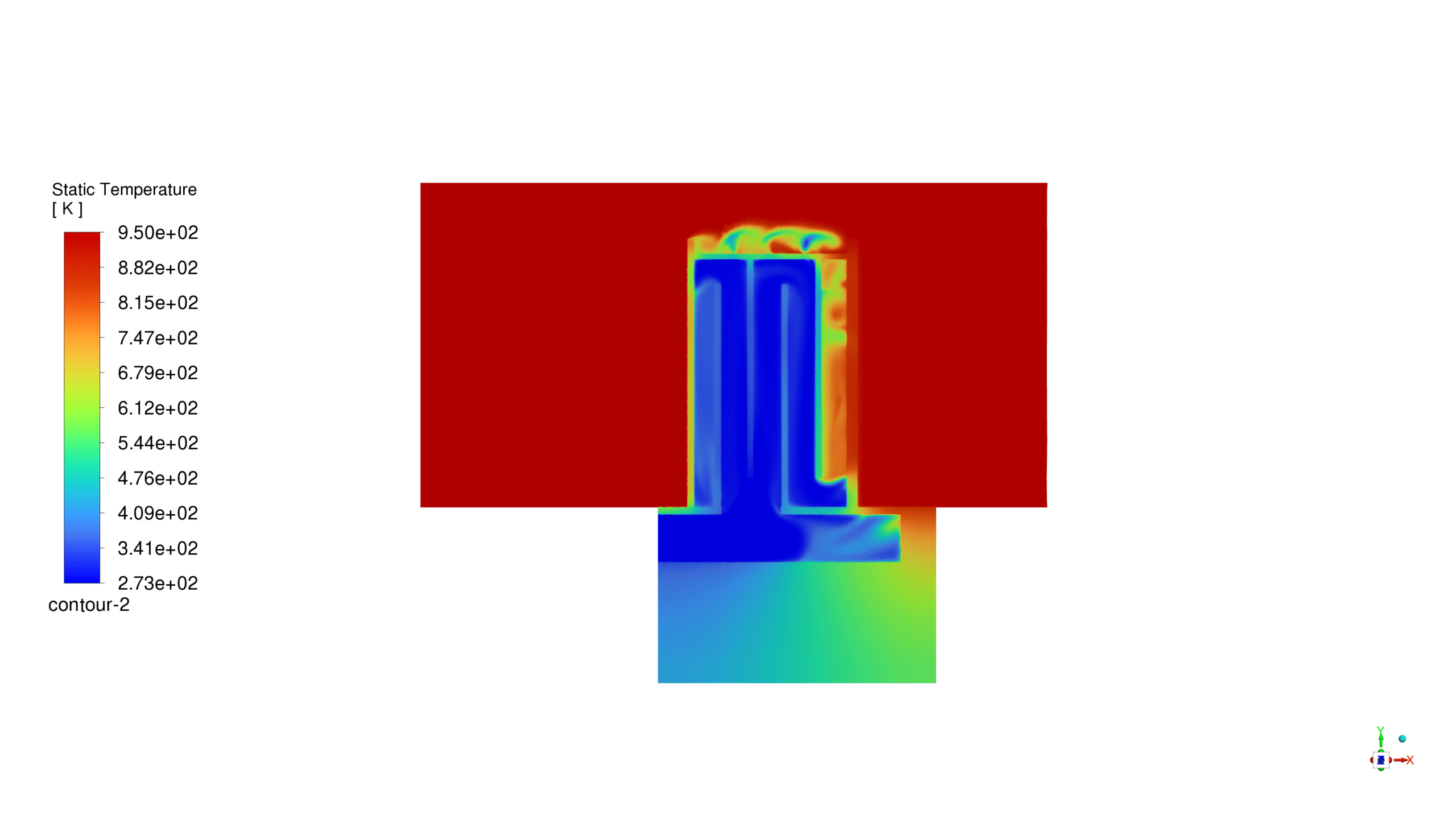
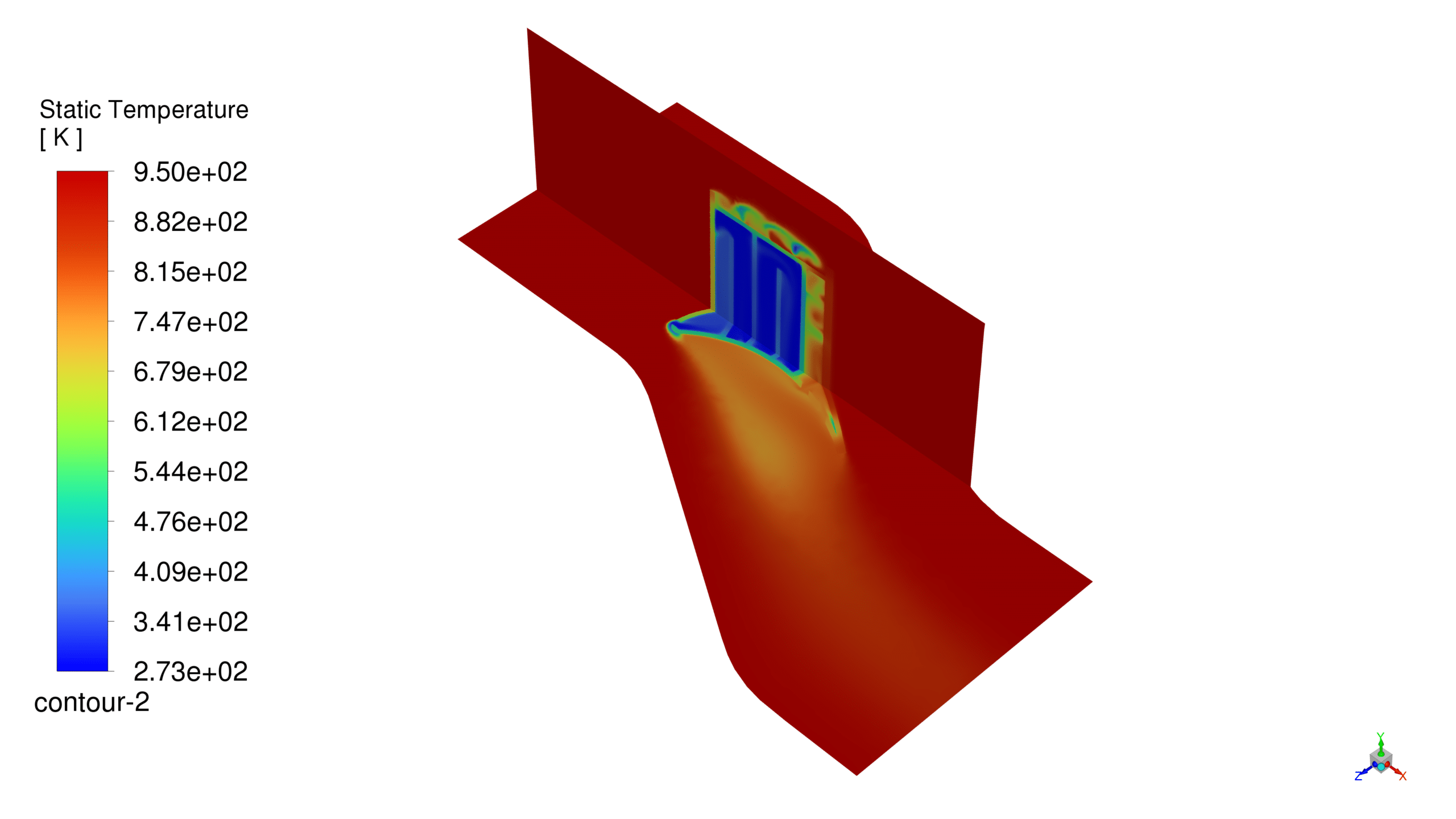
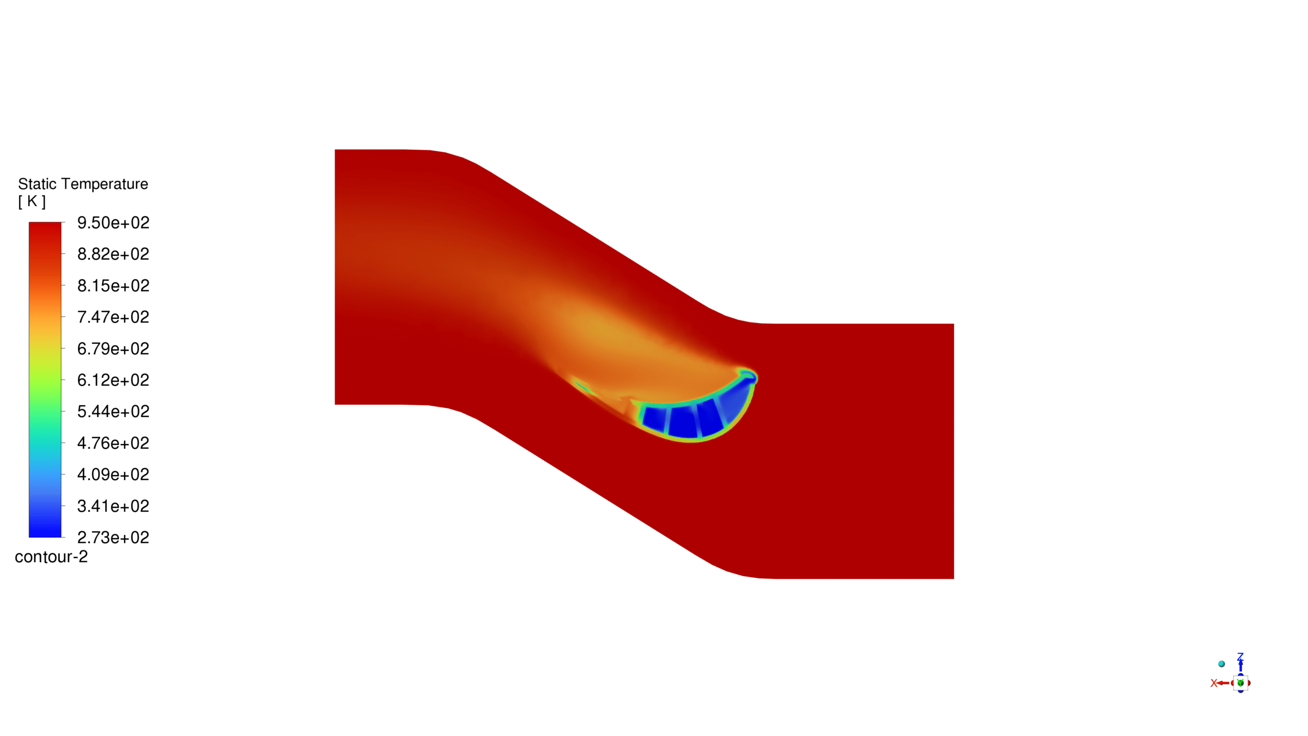
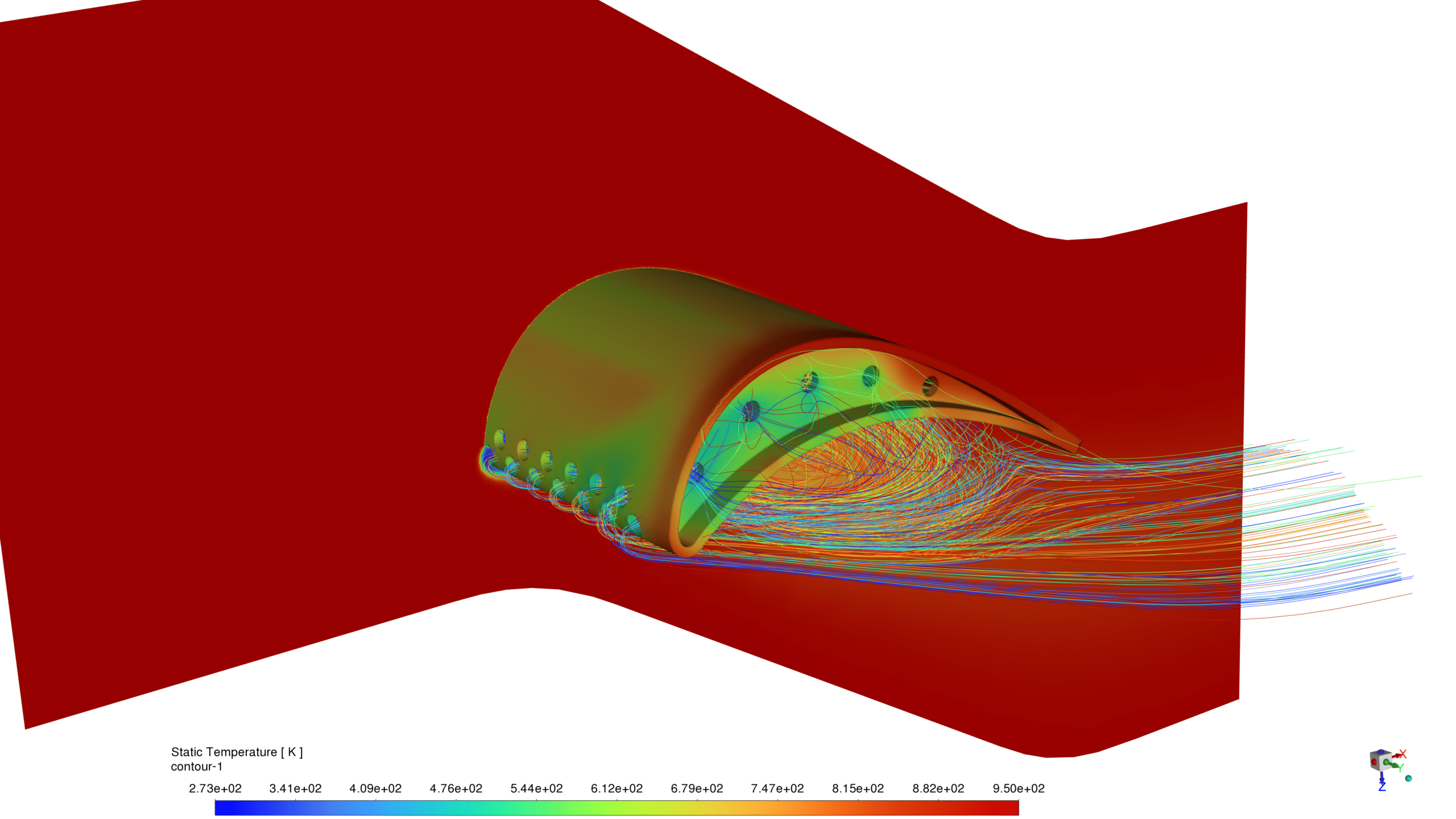
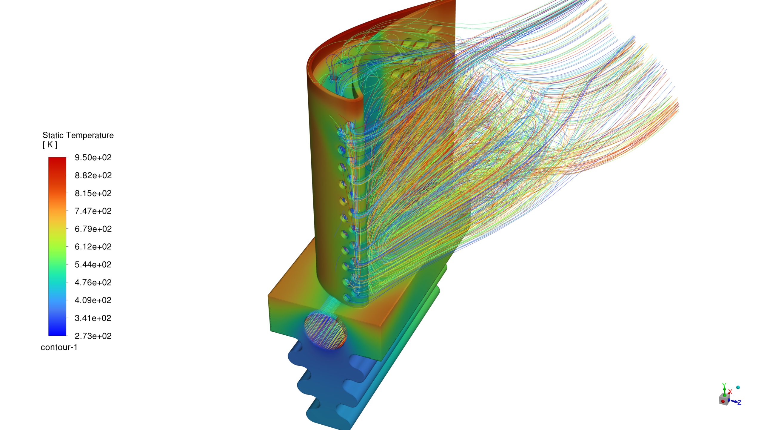
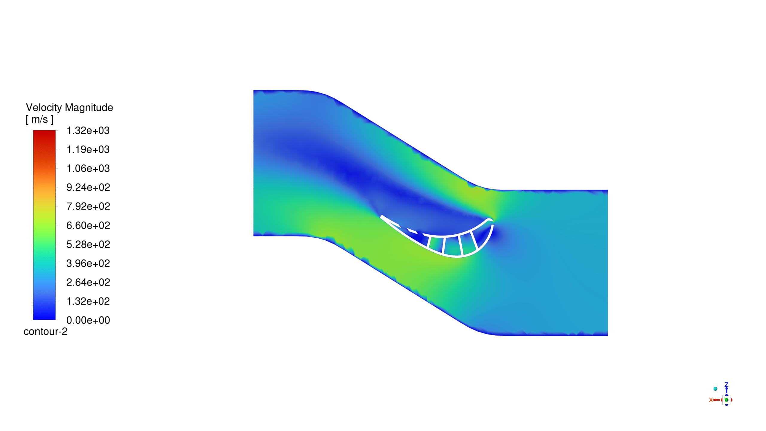
The simulation results showed the path lines of the cool air as it traveled inside the inner channels of the blade and exchanged heat with the hot gases flowing outside.
The path lines showed that the cool air effectively cooled the blade’s surface by forming a thin film around it. This thin film of cool air acted as a thermal barrier, reducing the heat transfer from the hot gases to the blade.
The simulation results also showed that the cooling air film generated around the blade’s surface effectively reduced the heat transfer from the hot gases to the blade. The thickness of the cooling air film varied along the blade’s surface, with thicker films observed at the film cooling holes. The cooling air film was also turbulent, indicating that the flow was mixing with the hot gases and reducing the heat transfer.




Reviews
There are no reviews yet.