Catalytic Reactor CFD Simulation by Eulerian Multiphase Flow, ANSYS Fluent Tutorial
$120.00 $60.00 Student Discount
- The problem numerically simulates the Catalytic Reactor using ANSYS Fluent software.
- We design the 3-D model by the Design Modeler software.
- We Mesh the model by ANSYS Meshing software, and the element number equals 430586.
- We use the Eulerian Multi-Phase model to define three phases, including air, fuel and catalyst material.
To Order Your Project or benefit from a CFD consultation, contact our experts via email (info@mr-cfd.com), online support tab, or WhatsApp at +44 7443 197273.
There are some Free Products to check our service quality.
If you want the training video in another language instead of English, ask it via info@mr-cfd.com after you buy the product.
Description
Description
The present problem simulates the flow inside a Catalytic Reactor using ANSYS Fluent software. We perform this CFD project and investigate it by CFD analysis.
The present model is designed in three dimensions using Design Modeler software. The present model is a cylindrical reactor designed vertically. The middle part of the model has four inlets for fuel injection and one inlet for the catalytic material.
The meshing of this project has been done with ANSYS Meshing software. The element number is 430586.
Catalytic Reactor Methodology
The present problem simulates the flow inside a catalytic reactor using ANSYS Fluent software. In the internal structure of this reactor, compressed air is mixed with the fuel spray into the reactor and the catalyst material to cause the reaction.
Therefore, in simulating this model, Eulerian multiphase flow is used. This multiphase model can solve momentum and conservation equations for each phase separately.
For this multiphase flow, three materials are defined; air with a density of 1.225 kg/m3 is introduced as the primary phase, fuel with a density of 10 kg/m3 and catalytic material with a density of 700 kg/m3 is introduced as secondary phases.
Airflow enters the reactor from the special air inlet in the lower part of the reactor with a mass flow of 4.095 kg/s, and catalytic flow with a mass flow of 409.49 kg/s enters from the middle pipe of the reactor.
Fuel enters through four reactor injectors with a flow rate of 81,898 kg/s through the middle of the reactor. Moreover, the standard k-epsilon model is enabled to solve turbulent fluid equations.
Catalytic Reactor Conclusion
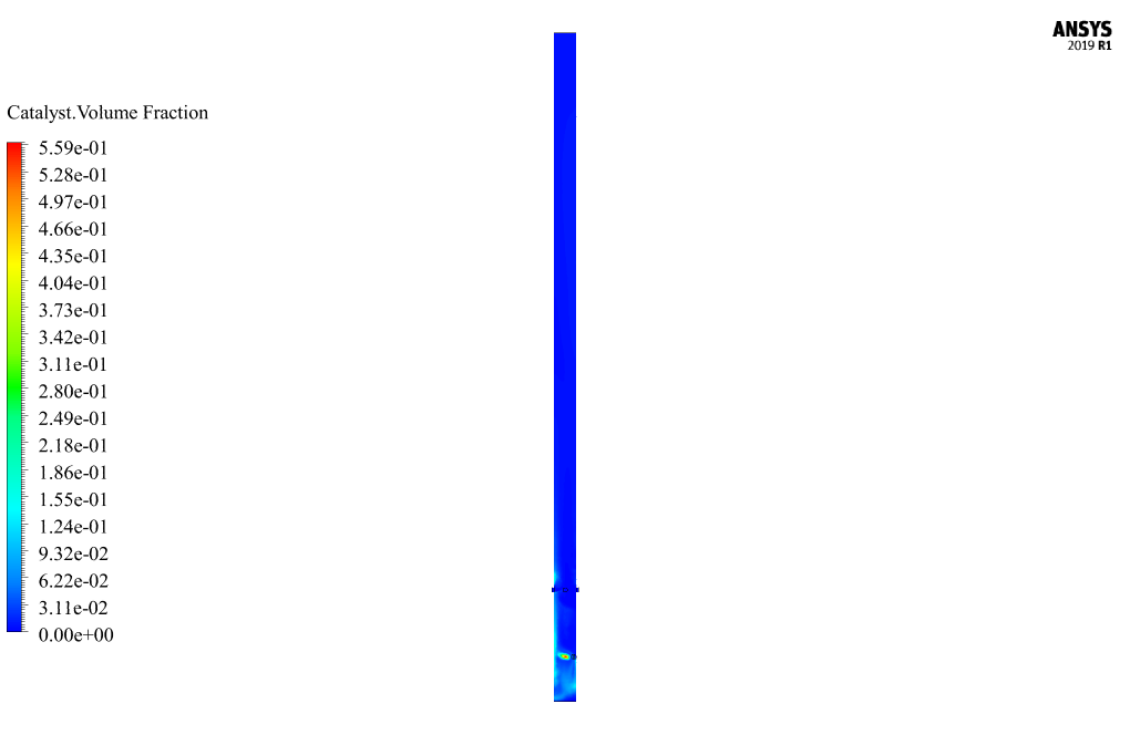
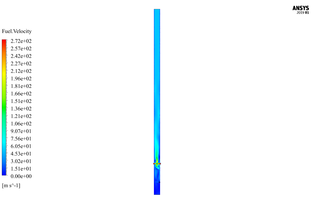
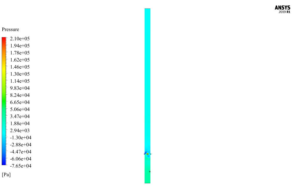
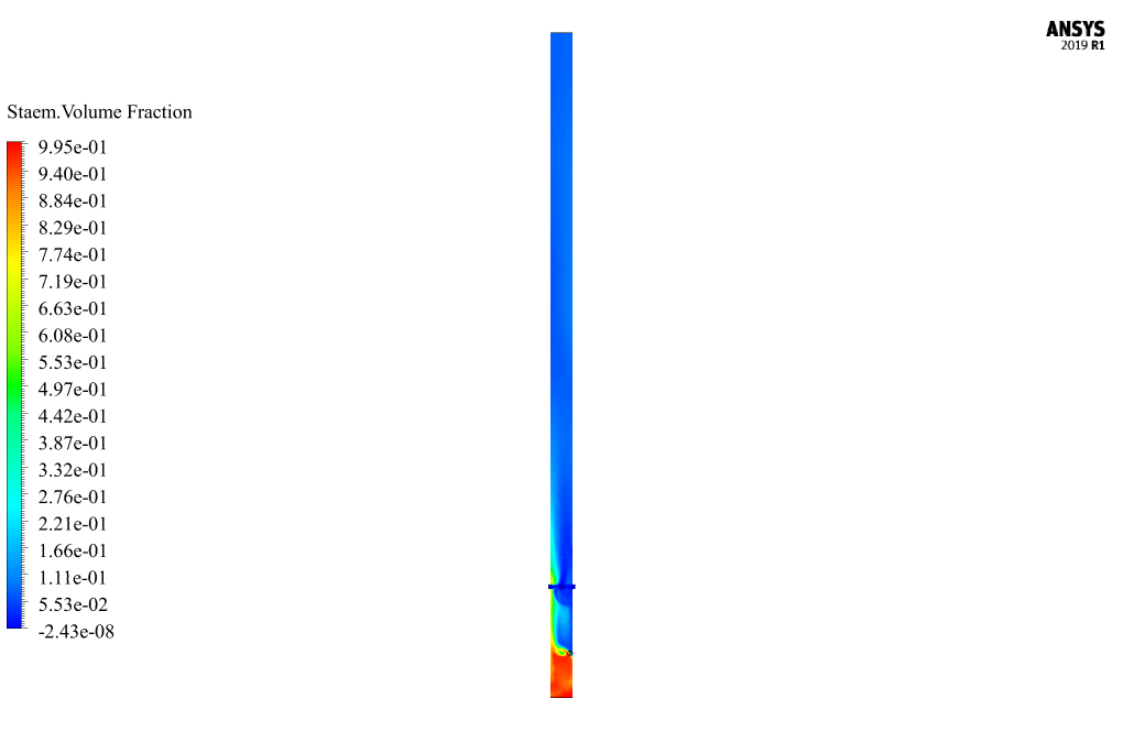
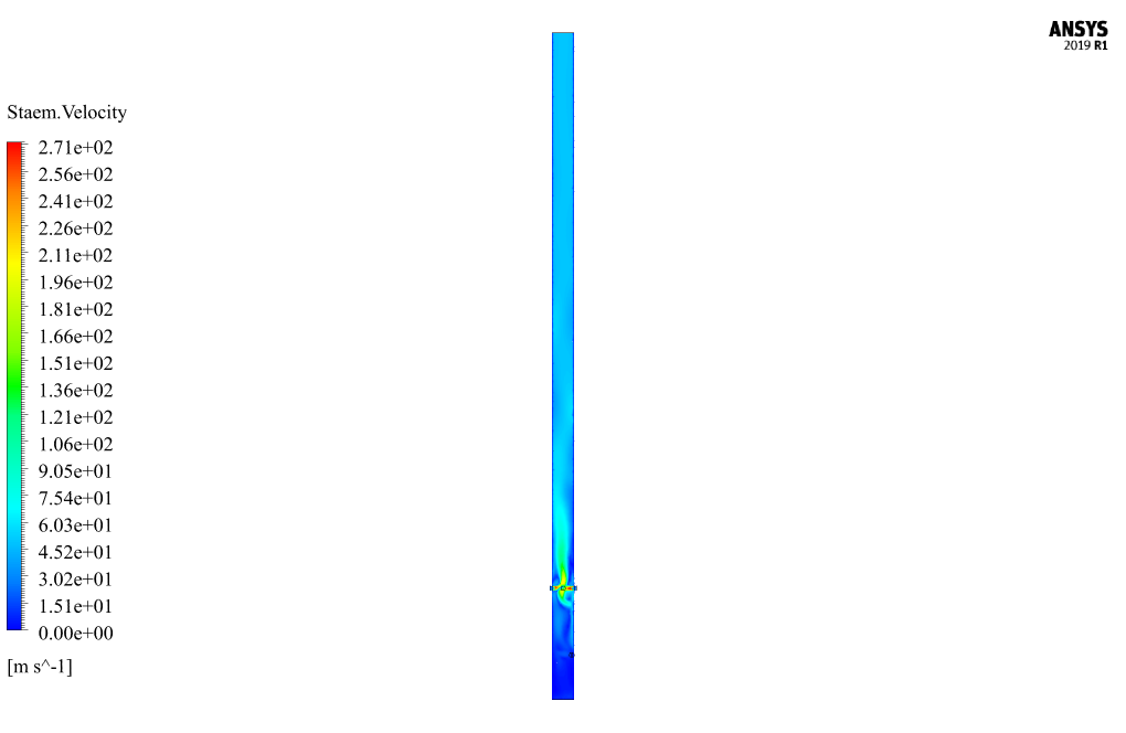
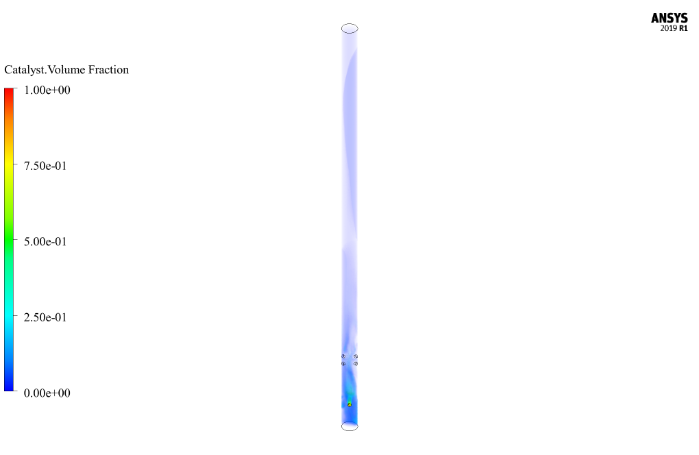
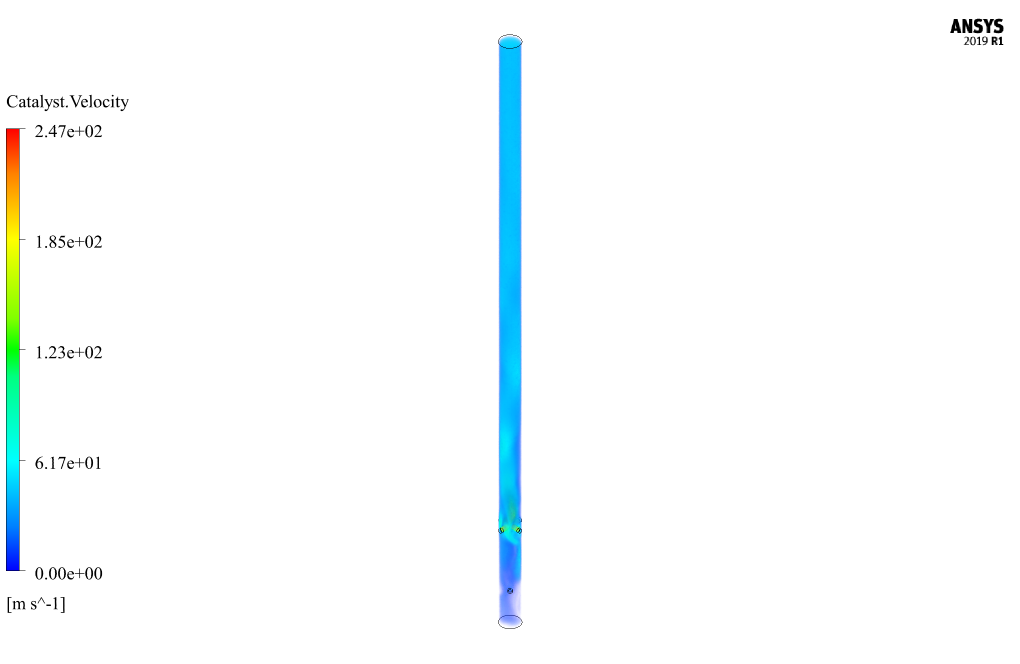
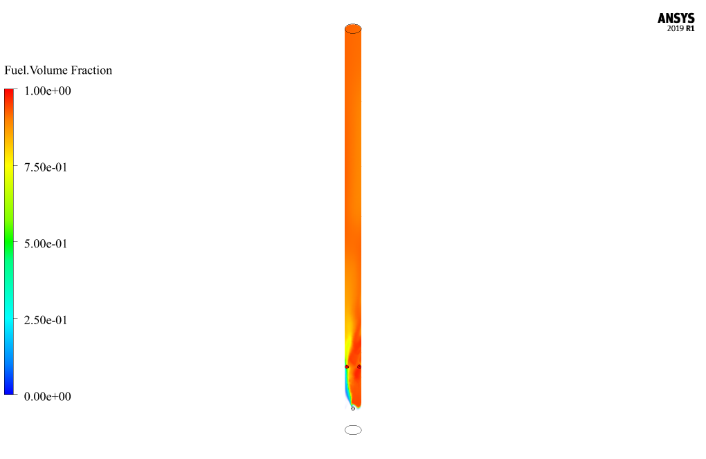
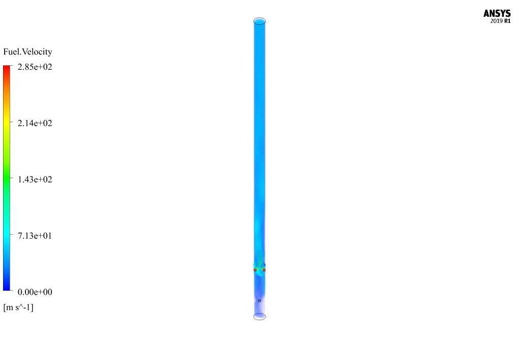
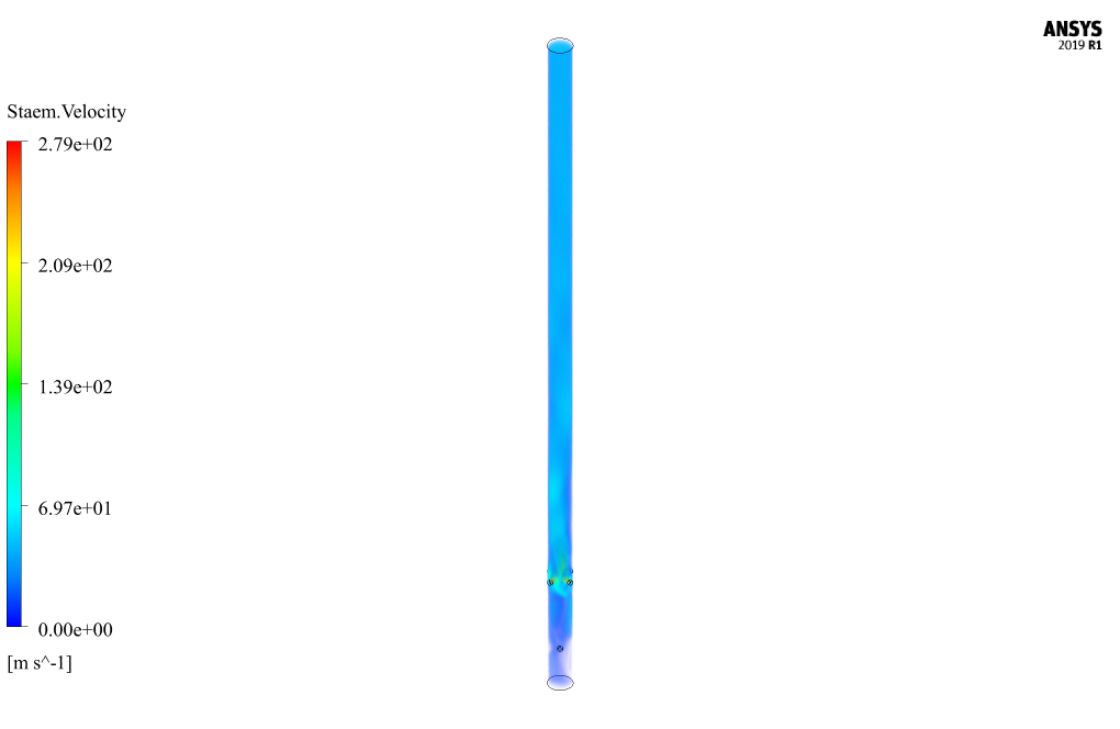
At the end of the solution process, two-dimensional and three-dimensional contours related to pressure, the velocity of each model phase (air, fuel, and catalytic material), and the volume fraction of each model phase (air, fuel, and catalytic material) are obtained.
As seen from the pictures, airflow enters from the bottom of the reactor and mixes with the fuel flows and the flow of catalytic material entering from the middle of the reactor.



Tomas Dach –
Can this simulation model the chemical reactions occurring in the catalytic reactor?
MR CFD Support –
Yes, the simulation includes a detailed reaction mechanism to model the chemical reactions occurring in the catalytic reactor. This allows it to accurately predict the conversion efficiency and product distribution.
Ernestine Gutkowski –
How does the Eulerian multiphase model handle the interaction between the gas and solid phases in this simulation?
MR CFD Support –
The Eulerian multiphase model treats each phase as a separate, interpenetrating continuum. This allows it to accurately capture the interaction between the gas and solid phases in the catalytic reactor, including the exchange of mass, momentum, and energy.
Electa Turner –
I watched the tutorial and it was really engaging. The visualization of the catalytic process made the concepts much clearer.
MR CFD Support –
Thank you so much for your kind words! We’re delighted to hear that the tutorial was engaging and helpful in visualizing the catalytic process. Our goal is always to provide clear and practical applications of CFD techniques through ANSYS Fluent tutorials. Your feedback is greatly appreciated and motivates us to continue creating quality educational content.
Mr. Ephraim Gorczany –
Is it possible to simulate different types of reactions occurring within the catalytic reactor, or is the simulation limited to specific reactions?
MR CFD Support –
In ANSYS Fluent, different types of reactions can be simulated within the catalytic reactor. The software allows for setting up various species and reactions within the reactor environment. These include surface reactions on the catalyst and homogeneous reactions in the fluid phases. The comprehensive reaction engineering capabilities in the software provide flexibility in defining reaction kinetics and mechanisms to match the specific needs of your project.
Gavin Schroeder –
I’m impressed with the complex flow simulation in this Catalytic Reactor tutorial. The multidisciplinary approach seems well-explained. Will I also learn how to interpret post-simulation data and optimize reactor performance based on the CFD results through this tutorial?
MR CFD Support –
Yes, the tutorial not only guides you on conducting the simulation but also covers the aspects of interpreting the results. You’ll learn to analyze the pressure, velocity, and volume fraction data for the various materials simulated. Furthermore, you will learn to use this data for optimization and performance enhancement of the reactor.
Raoul Wilkinson –
How does the simulation handle the heat transfer in the catalytic reactor?
MR CFD Support –
The simulation solves the energy equation to predict the temperature distribution in the catalytic reactor. This includes both conduction and convection heat transfer, as well as the heat generated by the chemical reactions.
Prof. Valentin Schuppe IV –
The tutorial was detailed and instructive. The step-by-step guidance through the setup and application of Eulerian multiphase flow in the catalytic reactor simulation was spot-on. I particularly appreciated the clarity around each material phase input. Visual representations in the form of two-dimensional and three-dimensional contours made understanding the flow and the process within the reactor straightforward. Excellent resource for anyone looking to understand the dynamics of catalytic reactors in-depth.
MR CFD Support –
Thank you very much for your kind words and positive review! We’re delighted to hear that the ANSYS Fluent tutorial for simulating catalytic reactors has been so helpful to you. It’s great that the visuals and the detailed explanation enhanced your understanding. If there’s anything else you’re curious about or if you need further assistance in your learning journey, feel free to reach out! 고맙습니다!
Mittie Jacobs –
What specific reactions take place within the catalytic reactor in this simulation, and how are they modeled?
MR CFD Support –
Admin response not found, please provide the data required to answer the question.
Lee Weissnat –
The review mentioned fuel injectors and a catalytic material inlet; what determines their placement within the reactor?
MR CFD Support –
In this simulation, the placement of fuel injectors and the catalytic material inlet is based on the need to optimize the mixing and reaction process inside the reactor. Their specific positions aim to facilitate efficient mixing of air with the fuel and effective contact with the catalytic material to ensure that the desired reactions occur efficiently within the CFD model.