Cavitation in a Cross-Flow Turbine CFD Simulation
$260.00 $130.00 Student Discount
In this project, Cavitation in a Cross-Flow Turbine With&Without Airfoil in the Entrance has been simulated and the results of this simulation have been investigated.
Click on Add To Cart and obtain the Geometry file, Mesh file, and a Comprehensive ANSYS Fluent Training Video.To Order Your Project or benefit from a CFD consultation, contact our experts via email (info@mr-cfd.com), online support tab, or WhatsApp at +44 7443 197273.
There are some Free Products to check our service quality.
If you want the training video in another language instead of English, ask it via info@mr-cfd.com after you buy the product.
Description
Cavitation in a Cross-Flow Turbine, Airfoil mode effect in the Entrance (3 models), CFD Simulation Training by Ansys Fluent
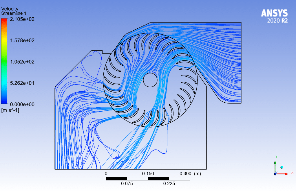
In this project, which has been done by the CFD numerical simulation method by Ansys Fluent software, cavitation has been simulated in a cross-flow turbine. Unlike most turbines where the flow is axial or radial, the fluid flows crosswise. This type of turbine has a low speed and is used for places where low head and high flow are required.
This project has been done in three main parts. In the first case, which is without an airfoil, but in the second case, to prevent cavitation, an airfoil is placed at the entrance, and in the third case, the angle of the airfoil compared to the second case is 15 degrees in a clockwise direction.
Geometry & Mesh
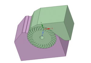
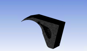
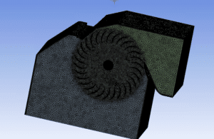
The three-dimensional geometry of this project is designed with SpaceClaim software. The length of the computational area is 664 mm, and width is 524 mm, and height is 280 mm.
Ansys Mashing produces the grid of the computational area, and the number of elements is 4915982 in case 1, 5544372 in case 2, and 5884179 in case 3, which is made of relatively small grid elements. And the meshing of the wall areas is also done correctly.
Cavitation CFD Simulation
To simulate the cavitation in a cross-flow turbine, we consider several assumptions:
- Due to the incompressibility of the flow, the pressure-based solver method has been selected.
- The simulation is steady.
Here is a summary of the steps for defining the problem and its solution in the following table:
| Viscous | k-epsilon | |
| k-epsilon model | RNG | |
| near-wall treatment | standard wall functions | |
| Multiphase Model | VOF | |
| number of Eulerian phases | 2 (water & vapor) | |
| formulation | implicit | |
| interface modeling | dispersed | |
| Boundary conditions | ||
| Inflow | velocity Inlet | |
| Velocity | 10 m/s | |
| volume fraction for liquid | 1 | |
| volume fraction for vapor | 0 | |
| Outflow | Pressure outlet | |
| gauge pressure | 101325 pascal | |
| volume fraction for liquid | 1 | |
| volume fraction for vapor | 0 | |
| Frame motion | On | |
| Fluid | Rotational velocity | 300rpm |
| Methods | ||
| Pressure-Velocity Coupling | Coupled | |
| Pressure | PRESTO | |
| momentum | second-order upwind | |
| volume fraction | second-order upwind | |
| turbulent kinetic energy | first-order upwind | |
| turbulent dissipation rate | first-order upwind | |
| Initialization | ||
| Initialization methods | Hybrid | |
Cavitation Results
Case 1
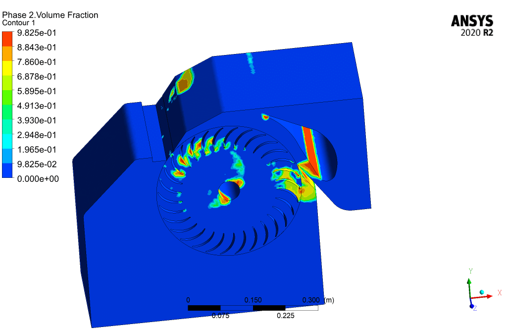
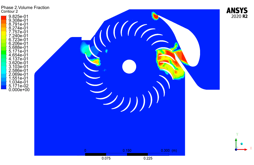
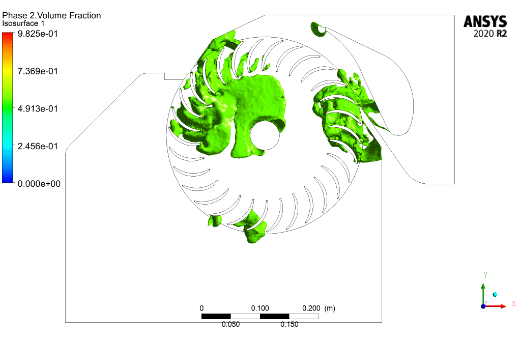
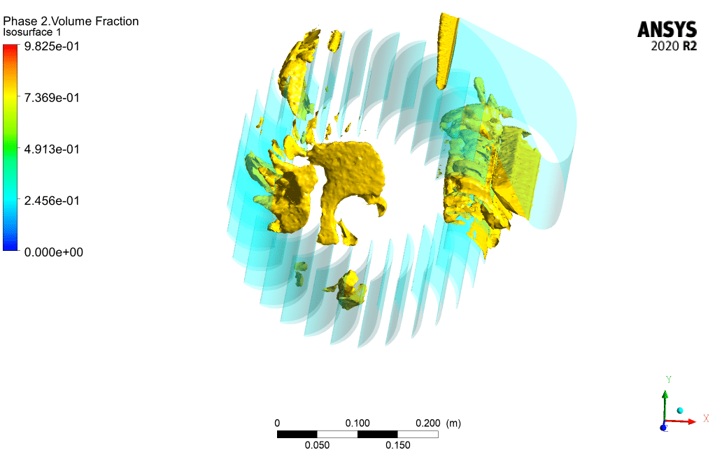
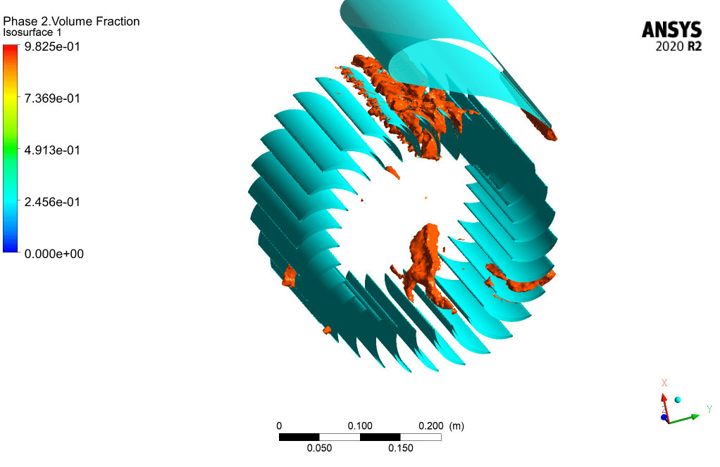
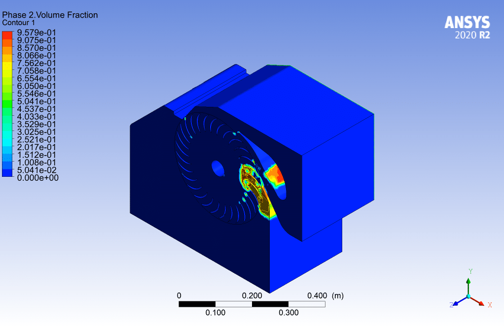
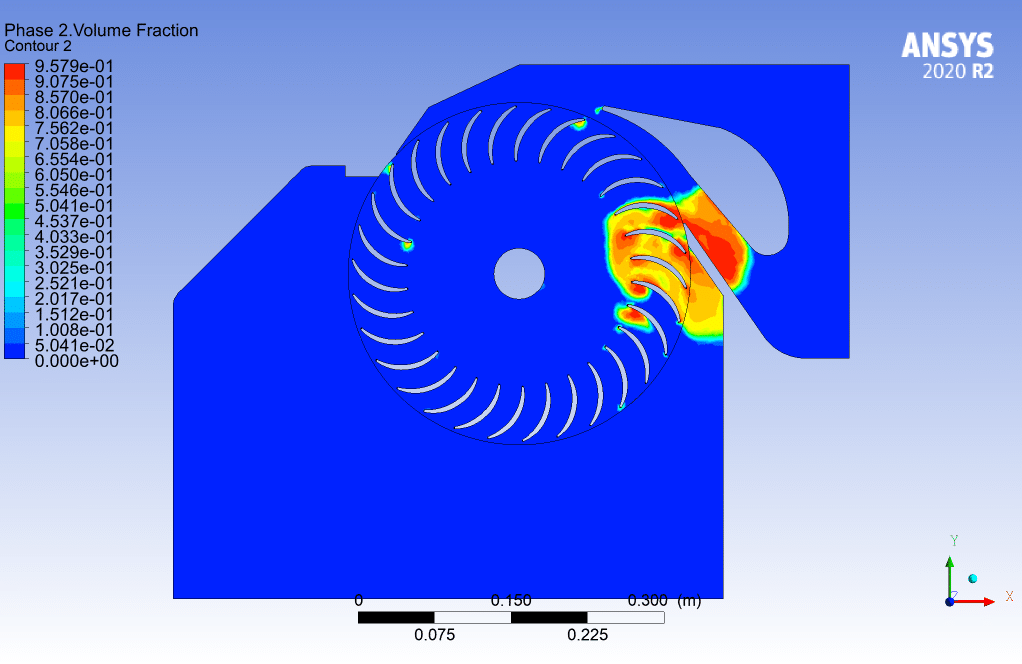
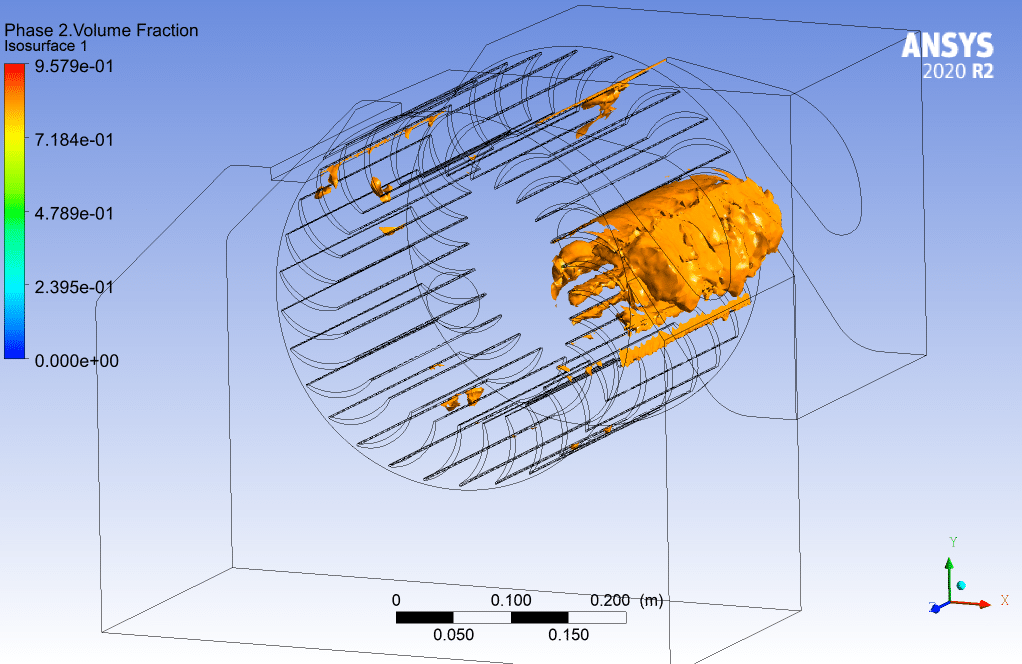
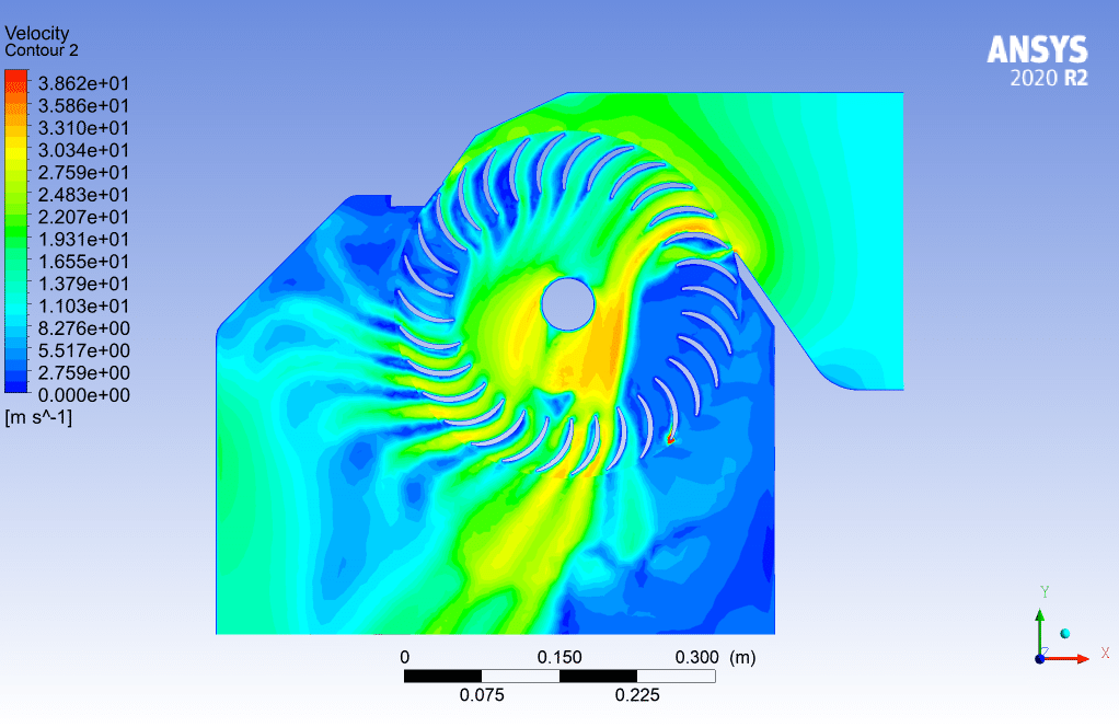
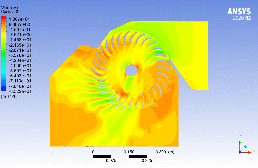
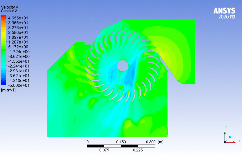
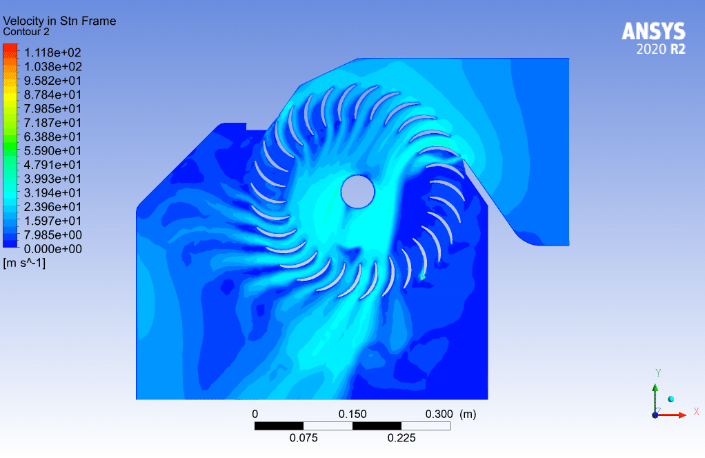
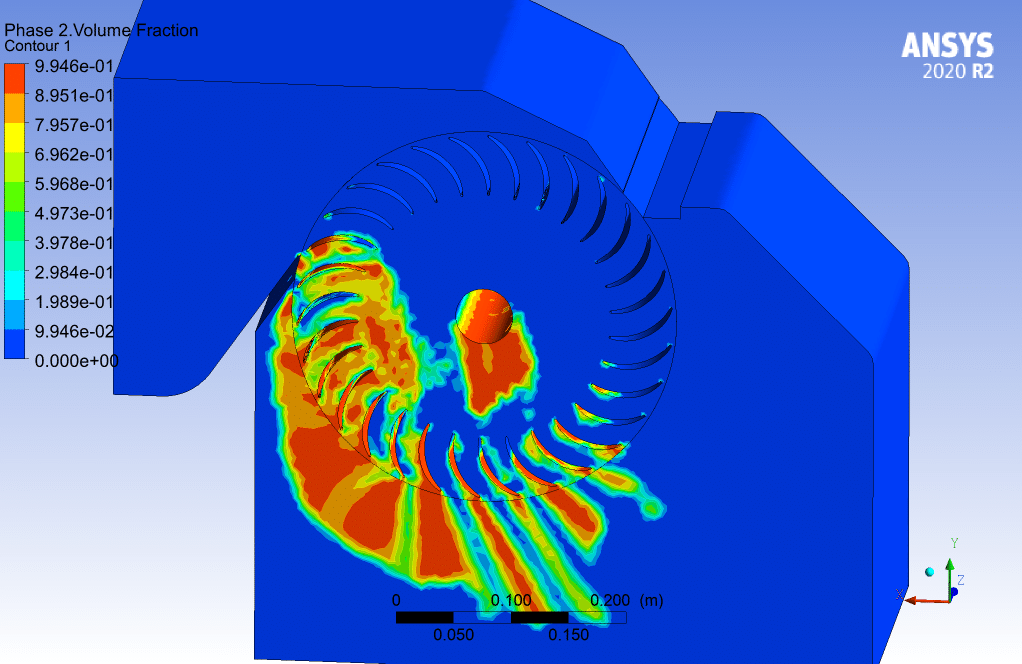
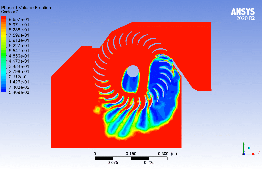
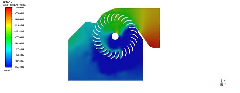
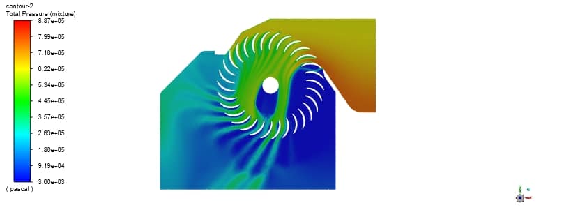
The cavitation phenomenon is a phenomenon that occurs in turbo cars and rotating blades. This phenomenon causes corrosion on the surfaces of the edges and is very destructive. In this simulation, according to the pressure contour, it is clear that in the right part of the blades. The pressure is shallow and less than the vapor pressure at that temperature, so the cavitation phenomenon occurs, and the phase change occurs. In other words, on the right side of the blade, this pressure drop is due to the suction made by the edges from the bottom to the top.
Case 2
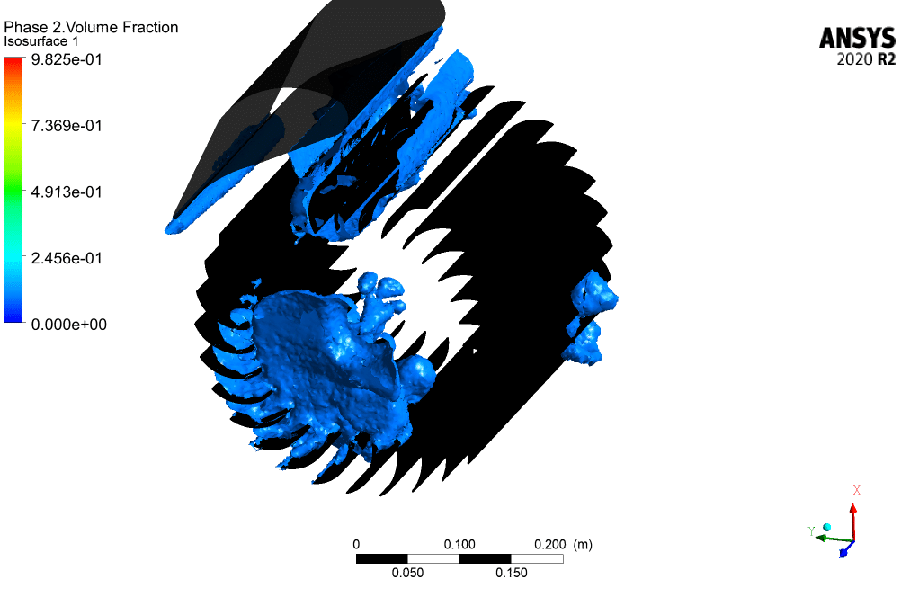
According to the previous case, an airfoil has been placed in the inlet of the turbine to prevent cavitation. It is formed on the airfoil itself, which can play a protective role, so this type of design can prevent cavitation.
Case 3
According to the previous case, an airfoil is placed at the inlet of the turbine to prevent cavitation, and the airfoil angle is rotated 15 degrees clockwise compared to the last case. The purpose of this step is to investigate the effect of changing the airfoil angle on intensity Cavitation
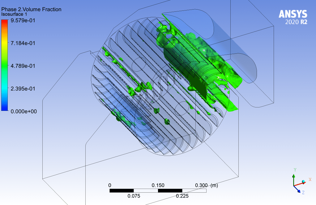
According to the contours taken from the volume fraction of the second phase, the amount of cavitation is slightly less than in the previous case, and it can be said that the rotation of the airfoil clock has been helpful for us.



Reviews
There are no reviews yet.