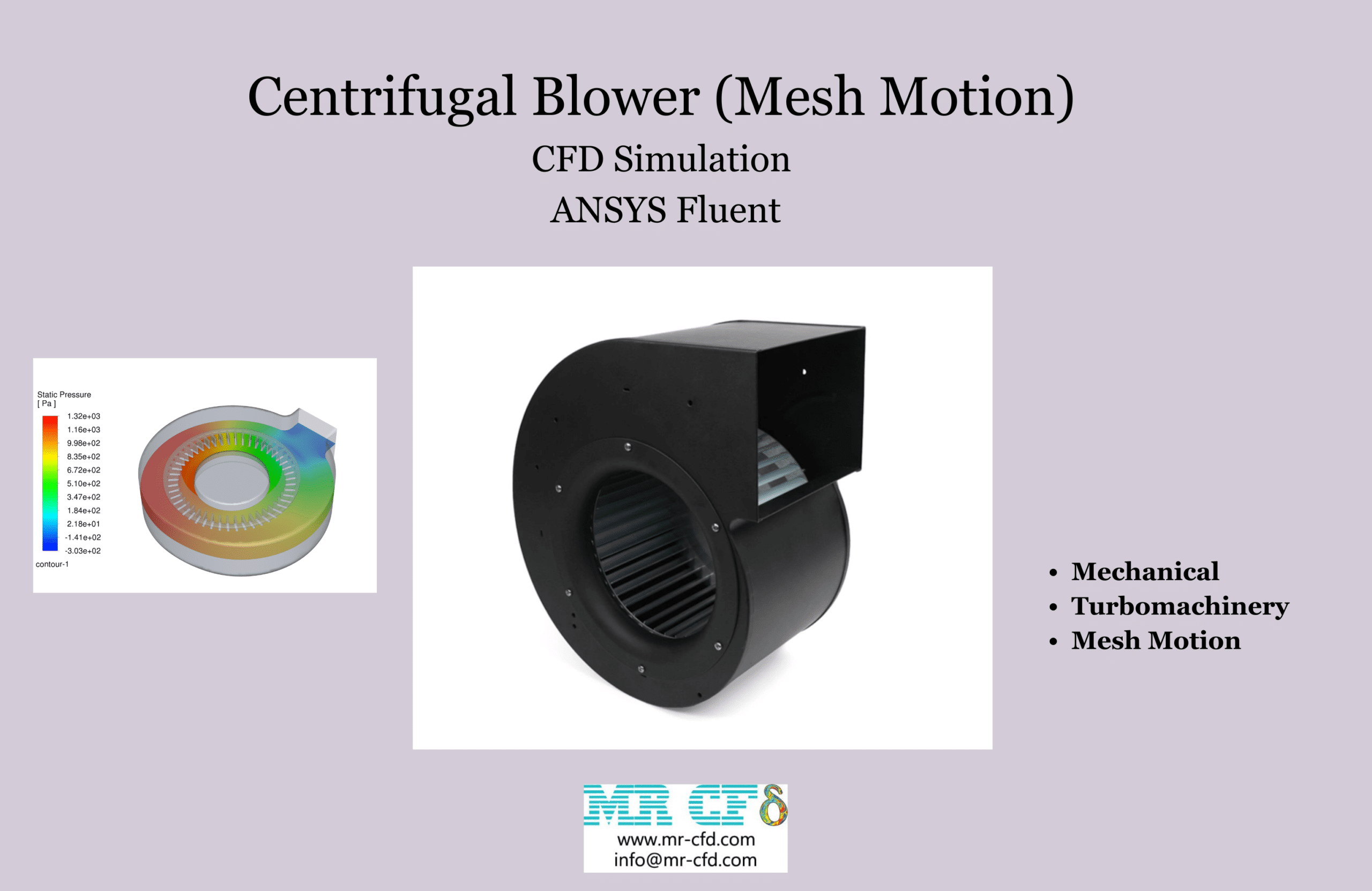
Centrifugal Blower (Mesh Motion) CFD Simulation, ANSYS Fluent
$100.00 $50.00 Student Discount
- The problem numerically simulates Centrifugal Blower using ANSYS Fluent software.
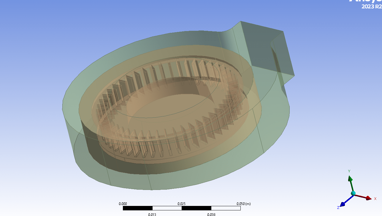
- We design the 3-D model by the Design Modeler software.
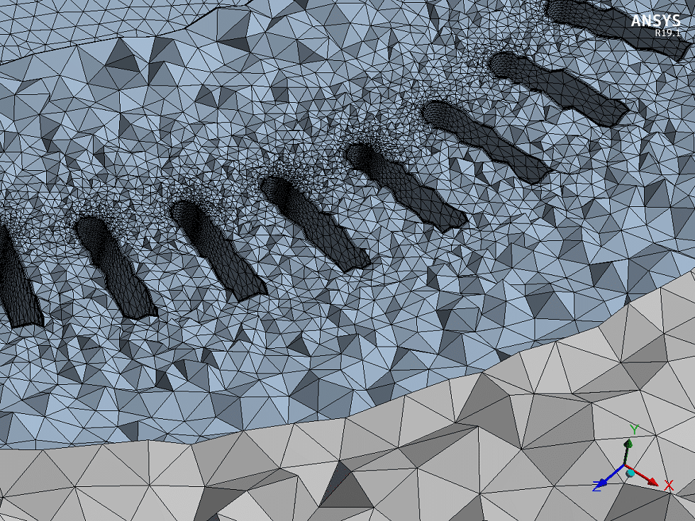
- We Mesh the model by ANSYS Meshing software, and the element number equals 5,479,874 .
- We use the Mesh Motion method to define rotational motion in cell zone conditions.
To Order Your Project or benefit from a CFD consultation, contact our experts via email (info@mr-cfd.com), online support tab, or WhatsApp at +44 7443 197273.
There are some Free Products to check our service quality.
If you want the training video in another language instead of English, ask it via info@mr-cfd.com after you buy the product.
Description
Description
This project simulates a Centrifugal Blower Considering Mesh Motion in ANSYS Fluent software. A centrifugal blower, also known as a centrifugal fan, is a type of industrial blower that uses the kinetic energy of a wheel to move air or gases. The wheel of a centrifugal blower is called an impeller, and it consists of a number of blades that are arranged around a central hub. The basic working principle of a centrifugal blower is as follows:
Air Inlet: Air enters the blower through the center of the impeller.
Rotation: As the impeller rotates, it imparts kinetic energy to the air.
Centrifugal Force: This kinetic energy is increased by the centrifugal force generated by the circular motion, which causes the air to move radially outwards.
Air Outlet: The air is then pushed out of the blower housing through a duct or outlet, which is typically a tangential or scroll-shaped discharge.
Centrifugal blowers are used in a wide range of applications, including :HVAC system for air conditioning, heating, and ventilating, industrial processes such as pneumatic conveying, combustion air supply, and exhaust systems, cooling systems for cooling electronic equipment or parts of machinery, and dust control in environments where dust needs to be collected or filtered out.
The 3-D geometry of the model is designed in Design Modeler software then meshed in ANSYS Meshing with 5,479,874 unstructured cells.
Methodology
In this simulation a rotating zone around the blades is considered in which the air flow rotates with 1500 [rpm] angular velocity. What we aimed to do in this simulation is to consider rotation of the blades with Mesh Motion. Mesh motion involves physically rotating or moving the mesh in the computational domain. This method is used when capturing the exact motion of the boundary and its interaction with the fluid is important. It’s typically used for unsteady simulations, like this simulation, where the motion of the mesh is an integral part of the physical phenomena being studied. Also the turbulence of the air flow is simulated via RNG k-e model.
Results
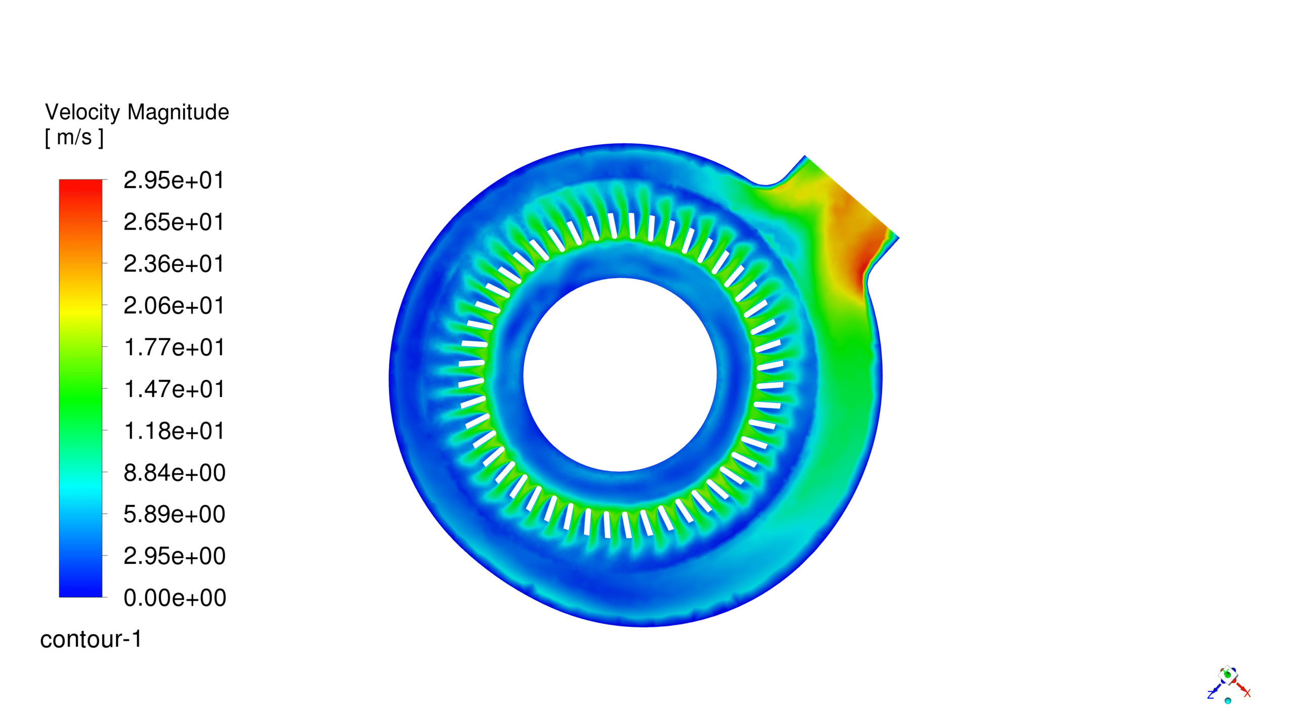
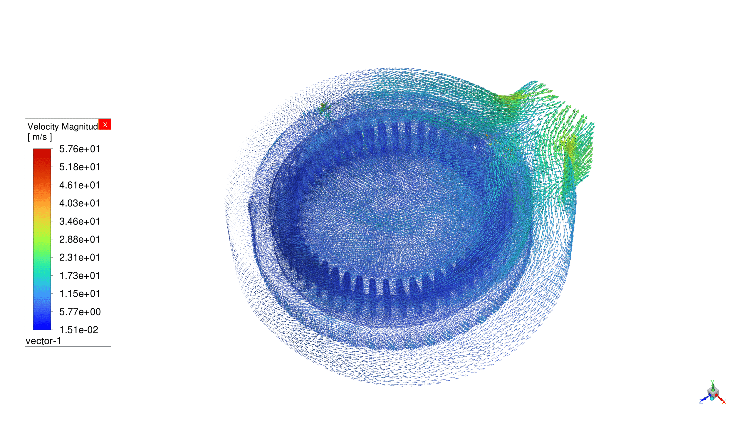
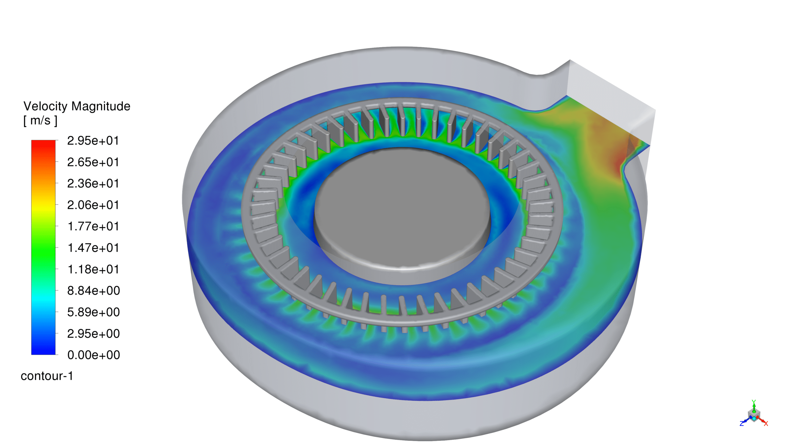
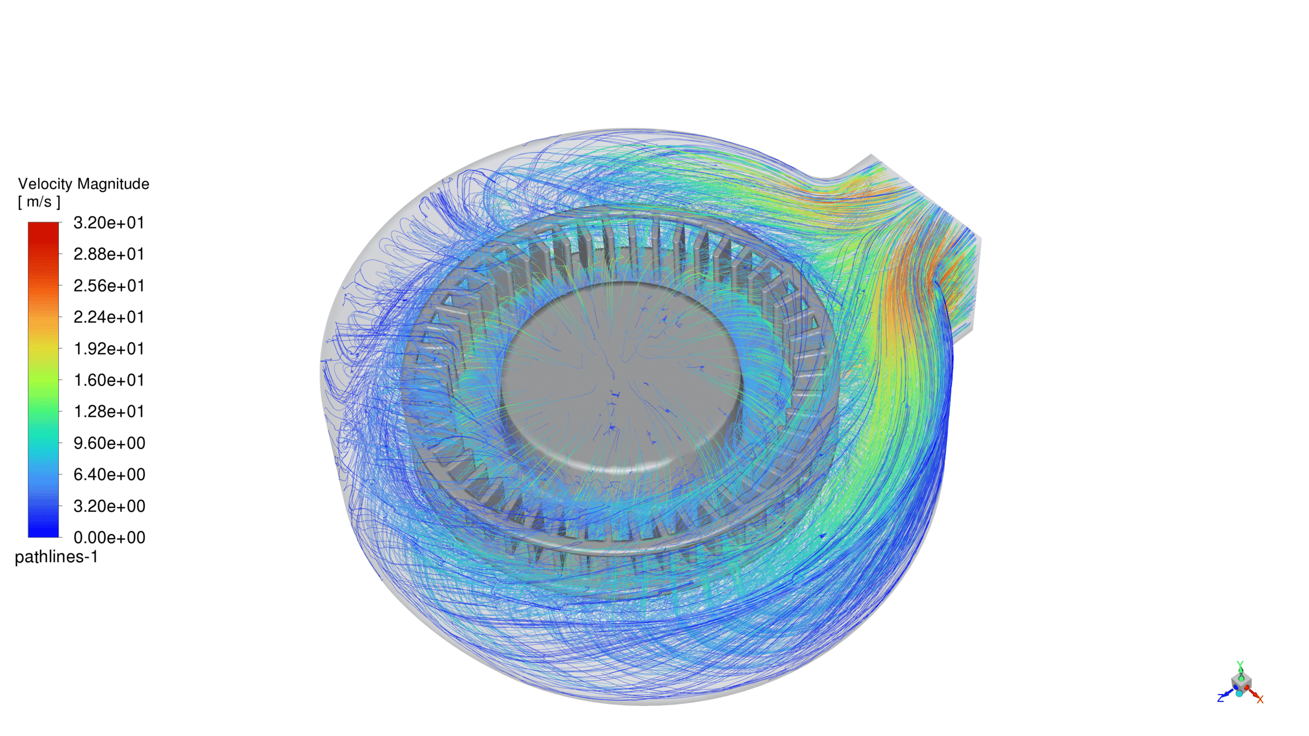
Following the simulation process, we acquired two-dimensional representations of various parameters: pressure, velocity, and streamlines. In addition, we also gathered two-dimensional visualizations of pathlines and velocity vectors.
The findings indicate that the airflow is drawn into the central region of the blower, where it undergoes a high-pressure rotational movement near the blade areas. Subsequently, both the pressure and velocity of the airflow escalate and are channeled outward through the blower’s discharge.
Related products
-
Cyclone by DPM ANSYS Fluent CFD Simulation Training
Rated 5.00 out of 5$120.00$60.00 Student Discount


Reviews
There are no reviews yet.