Centrifuge CFD Simulation, Two-Phase Flow (MIXTURE), ANSYS Fluent
$140.00 $70.00 Student Discount
In this project, the effect of the steady rotation of a centrifugal turbine on a water and air two-phase mixture is investigated.
Click on Add To Cart and obtain the Geometry file, Mesh file, and a Comprehensive ANSYS Fluent Training Video.To Order Your Project or benefit from a CFD consultation, contact our experts via email (info@mr-cfd.com), online support tab, or WhatsApp at +44 7443 197273.
There are some Free Products to check our service quality.
If you want the training video in another language instead of English, ask it via info@mr-cfd.com after you buy the product.
Description
Centrifuge Problem description
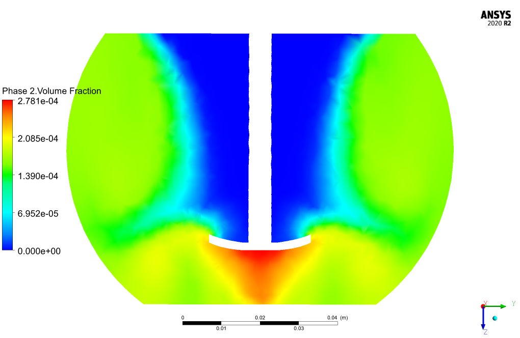
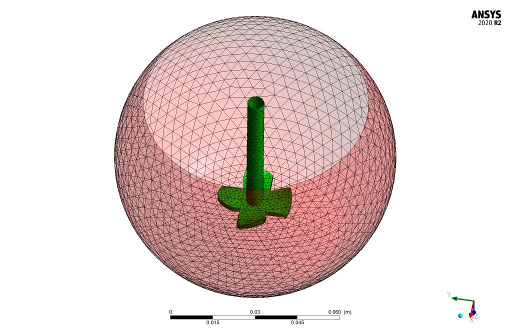
In this project, the effect of steady rotation of a centrifugal turbine on a water and air two-phase mixture is investigated by ANSYS Fluent software. Multi-phase MIXTURE model is used to solve water and air phase interactions. The secondary phase (air) volume fraction has very low values in the 0.0001 order, which proves the validity of the mixture multi-phase model in this project, since for applying the Mixture Multi-Phase model, the secondary phase volume fraction should be less than 15%. Slip velocity has been taken into account at the water and air contact interface. The diameter of air bubbles is considered equal to 1 µm. The rotating region of the turbine is considered a separate body that rotates with a rotational speed equal to 500 rpm, which simulates the rotation of the centrifugal turbine at the same rate. Frame Motion (MRF) model has been applied for the rotation simulation.
Centrifuge Geometry and mesh
The geometry of the fluid domain is designed in the Design modeler and the computational grid is generated using Ansys meshing. The mesh type is unstructured, and the element number is 126000.
Solver Configuration for Centrifuge CFD Simulation
Critical assumptions:
- Solver type is assumed Pressure Based.
- Time formulation is assumed to be Steady.
- Gravity effects are considered in a positive Z direction equal to 9.84 m/s2.
The following table a summary of the defining steps of the problem and its solution.
| Models (Centrifugal Turbine) | ||
| Multiphase | Model | Mixture |
| Slip velocity | Activated | |
| Number of Eulerian phases | Two | |
| Volume fraction parameters | Implicit | |
| Interface modeling | Dispersed | |
| Primary phase | Water | |
| Secondary phase | air | |
| Phase interaction | Drag (schiller-naumann) | |
| Slip velocity | Manninen et al. | |
| Viscous | k-epsilon | RNG |
| RNG option | Swirl dominated flow | |
| Near wall treatment | Standard wall function | |
| Materials (Centrifugal Turbine) | ||
| Air | Definition method | Fluent Database |
| Material name | Air | |
| Density | 1.225 kg/m3 | |
| Viscosity | 1.7894e-05 kg/m.s | |
| Water | Definition method | Fluent Database |
| Material name | Water | |
| Density | 998.2 kg/m3 | |
| Viscosity | 0.001003 kg/m.s | |
| Cell zone conditions (Centrifugal Turbine) | ||
| Turbine | Material name | mixture |
| Frame motion | On | |
| Rotational velocity | 500 rpm | |
| Boundary conditions (Centrifugal Turbine) | ||
| Outlet | Type | Pressure outlet |
| Gauge pressure | 0 atm | |
| Solver configurations (Centrifugal Turbine) | ||
| Pressure-velocity coupling | Scheme | SIMPLE |
| Spatial discretization | Gradient | Least square cell-based |
| Pressure | PRESTO! | |
| Momentum | First order Upwind | |
| Volume fraction | First order Upwind | |
| Turbulent kinetic energy | First order Upwind | |
| Turbulent dissipation energy | First order Upwind | |
| Initialization | Gauge pressure | 0 Pa |
| X velocity | 0 m/s | |
| Y velocity | 0 m/s | |
| Z velocity | 0 m/s | |
| Turbulent kinetic energy | 1 m2/s2 | |
| Turbulent dissipation rate | 1 m2/s3 | |
Results and discussion
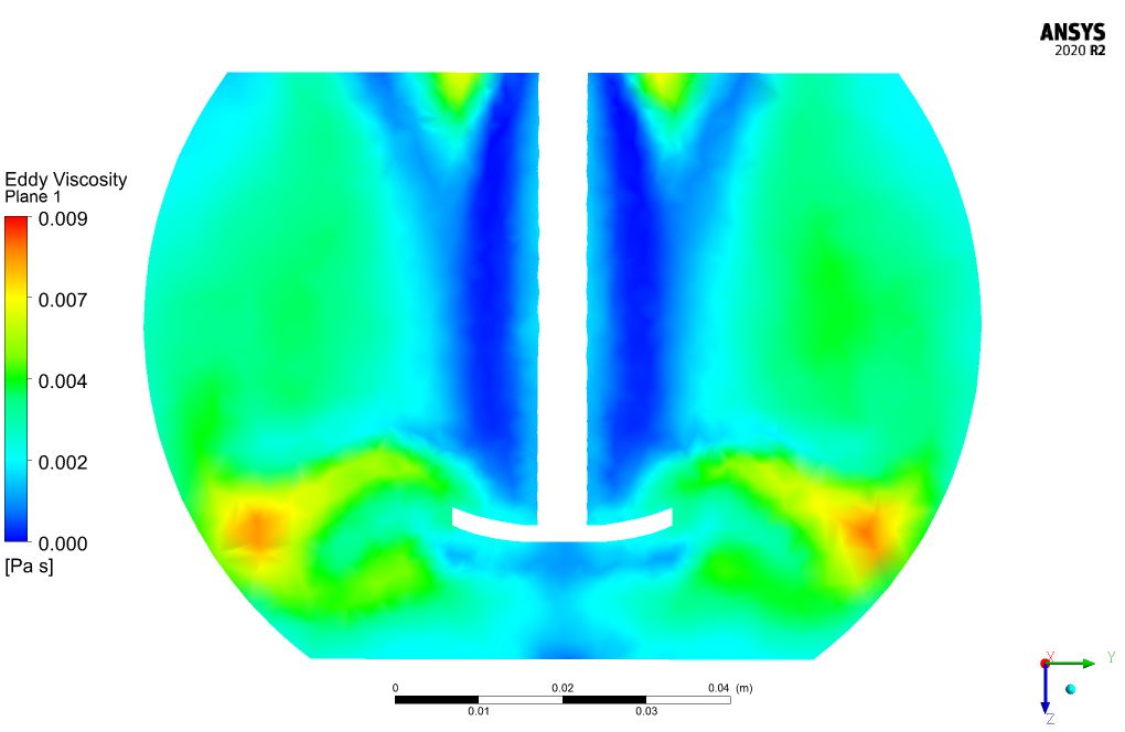
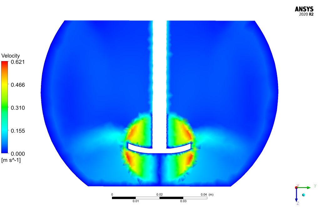
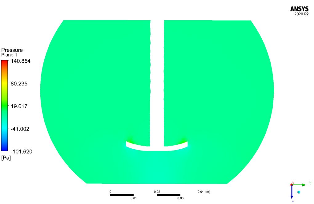
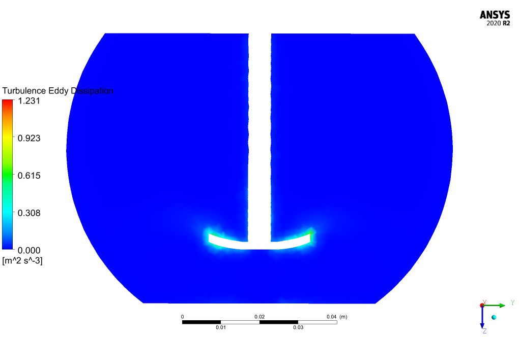
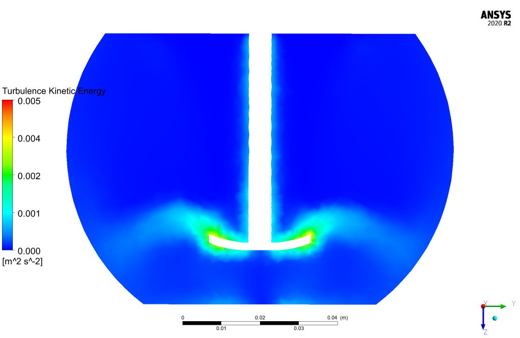
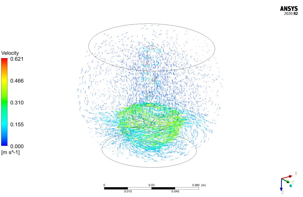
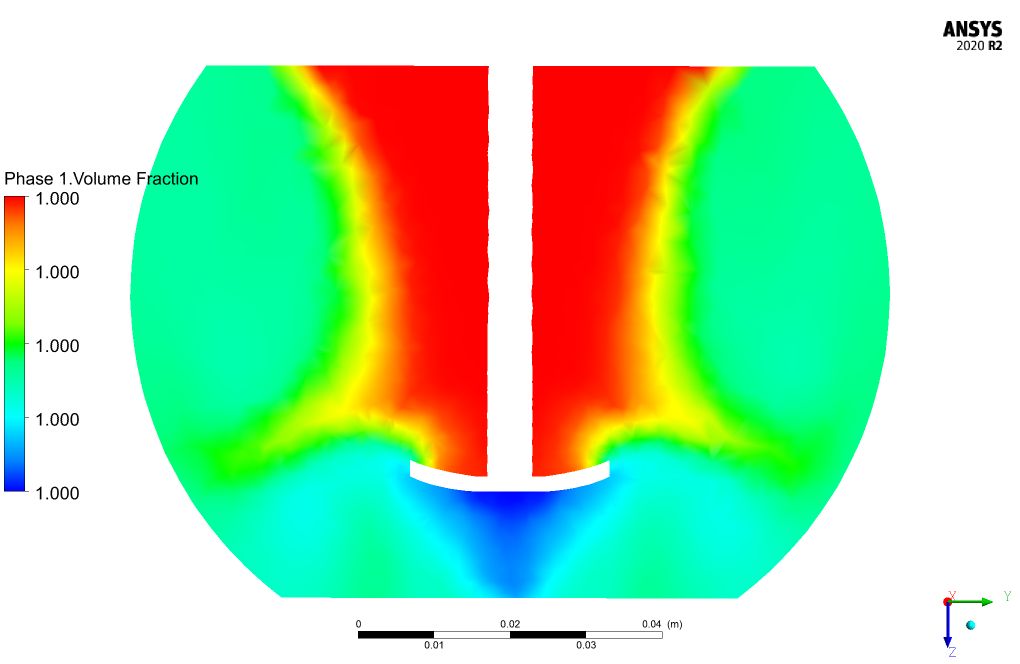
Rotation of the centrifugal turbine with the rotational speed of 500 rpm results in fluid movement with a velocity equal to 0.62 m/s at close ranges of the turbine. Water bubbles are captured under the turbine which increases the secondary phase (air) volume fraction in these regions.



Mrs. Macie Dibbert II –
I appreciated the depth of detail in the Centrifuge CFD simulation product, especially the balance between realism and computational feasibility by constraining the secondary phase volume fraction. The visualization provided helped immensely in understanding the complex interactions at play.
MR CFD Support –
Thank you for your positive feedback! We’re thrilled to hear that our product met your expectations and provided you with a clear understanding of the two-phase flow interactions within a centrifugal turbine environment. We strive to deliver detailed and accurate simulations to support your learning and research needs.
Marianne Leffler –
Fantastic course! It really helped me understand the complexities of two-phase flow and the usage of the Mixture model. I can now comfortably set up and solve multiphase problems in ANSYS Fluent thanks to the clear explanations and steps provided.
MR CFD Support –
Thank you for the positive feedback! We’re thrilled to know our Centrifuge CFD Simulation course met your learning needs and helped you gain confidence in using ANSYS Fluent for multiphase flows. If you ever have any further questions or need support in future projects, do not hesitate to reach out.
Brigitte Dooley –
The tutorial on the Centrifuge CFD Simulation was excellent! I learned a lot about the two-phase flow and the MIXTURE model using ANSYS Fluent. Especially the explanations on how to apply slip velocity and the distinction between primary and secondary phases were clear and informative. The complex interaction between water and air was depicted effectively. It was also impressive to see the effect of the turbine’s rotation on fluid movement. Great work!
MR CFD Support –
Thank you for your positive feedback! We’re delighted to hear that you found the tutorial on the Centrifuge CFD simulation using ANSYS Fluent informative and that it helped in understanding the two-phase flow dynamics and the application of the MIXTURE model. We strive to provide clear and effective educational content, and it’s wonderful to know that the explanations met your expectations. If you need further assistance or have more questions in the future, feel free to reach out. Thank you for choosing MR CFD for your learning needs!
Adaline Collins –
I’m impressed by the detail and success in modeling the two-phase flow in a centrifugal environment! The mixture model choice and careful consideration of the slip velocity and bubble size indicate a robust set-up. Thorough and insightful work!
MR CFD Support –
Thank you for the positive feedback! We’re thrilled to hear that the detail and considerations in model setup met your expectations and led to a successful simulation. We’re committed to providing quality educational resources and support. If you have any further questions or need more information about similar simulations, don’t hesitate to ask. We’re here to help!
Elinor Lind –
What kind of performance improvements could I expect in an actual centrifuge design after running this simulation? Could you provide me with more details on that?
MR CFD Support –
The simulation helps determine the fluid dynamics within the centrifuge and visualizes the behavior of the air-water mixture due to the rotation of the turbine. The performance improvements that are typically expected include better efficiency in particle separation, reduced turbulence for a smoother process, and optimized bubble size and distribution in the mixture to enhance separation. Through the analysis, one can achieve an improved understanding of phase distribution and implement design adjustments that lead to better operation and energy efficiency.
Colby Stamm –
The detailed centrifuge problem description and setup sounds impressive! How well did the simulation predict the bubble size distribution and was there any additional validation done against experimental data?
MR CFD Support –
Our simulation parameters were carefully chosen to mimic the centrifugal turbine’s environment, and we used a 1 µm bubble diameter within our configurations. The simulation was successful in predicting the behavior of the air-water mixture under the influence of the turbine’s rotation, including a realistic distribution of air bubbles within the mixture. At this stage, there are no validations against experimental data provided within this description, but the simulated predictions are consistent with established physical principles guiding such processes.
Eleazar Kuhic –
I’m very intrigued by the detail in specifying important parameters. The use of MIXTURE model for simulating two-phase flow – how does choosing this over other models affect the simulation results?
MR CFD Support –
Hello! Opting for the MIXTURE model for two-phase flow simulations can greatly influence the results as this model is particularly effective for systems where the secondary phase volume fraction is small and where the spatial distribution of phases is relatively uniform. This can be the case in our centrifuge where air constitutes only a minor part (less than 15%) of the total volume. Using the MIXTURE model likely simplifies calculations and provides high-fidelity results for the interaction between water and air phases under the specified parameters of the centrifugal turbine environment.
Tiara Marvin –
The detailed simulation process for this centrifugal turbine project is impressive! The multi-phase MIXTURE model clarity and the explanation of the conditions for its application help in understanding the appropriateness of the model for the simulated scenario. The inclusion of MRF to accommodate rotation simulation demonstrates thoroughness in approaching real-world applications. Great job on addressing each phase’s interaction and the solver configurations used.
MR CFD Support –
Thank you for your positive feedback on our Centrifuge CFD Simulation tutorial! We’re delighted to hear that the information provided was clear and useful. We always strive to ensure our simulations are as accurate and informative as possible. If you have any further questions or need additional guidance, don’t hesitate to reach out.
Amaya Moen DVM –
I’m blown away by the precise turbulence and phase interaction settings in the Centrifuge CFD Simulation product! The depth and detail of this simulation must provide incredible insights into the fluid dynamics involved.
MR CFD Support –
Thank you for the positive feedback on our Centrifugal simulation training! We’re thrilled to hear you appreciated the detailed setup of turbulence and the multiphase interaction. If you ever need further insight into our simulations or have additional questions, don’t hesitate to ask!
Dee Stanton DVM –
I’m fascinated by the role of the MRF Model in this simulation. Could you explain the advantage of using MRF for this scenario?
MR CFD Support –
The Multiple Reference Frame (MRF) model is advantageous in this scenario as it provides a simplified yet effective way to simulate the steady-state rotational effects of the turbine without calculating the motion of the rotary region directly. By using MRF, the computational demand is significantly reduced, which allows for a faster simulation while still capturing the essential flow characteristics of the rotation.
Sarina Cummings –
Your course on centrifuge CFD simulation is exceptionally detailed. Learning about the mixture multiphase model and its application to simulate a centrifuge with two-phase flow was fascinating. The explanation of how slip velocity at the water and air interface is modeled, and inclusion of detailed solver configurations has really solidified my understanding. Great job on designing a practically-relevant project!
MR CFD Support –
Thank you so much for your kind words! We are thrilled to hear that you found the centrifuge CFD simulation course informative and useful. Our goal is to provide high-quality, detailed simulations that are directly applicable to real-world engineering problems. Your feedback is greatly appreciated, and we look forward to providing you with more helpful learning products in the future.
Hilario Reichel –
The simulation includes impressive detail in terms of modeling turbulent flow dynamics. Was there data provided on the turbulence captured by the RNG k-epsilon model near the rotating turbine?
MR CFD Support –
We appreciate your attention to the depth of our analysis. Indeed, the RNG k-epsilon turbulence model offers enhanced accuracy in capturing the swirling flows near the moving parts such as the rotating turbine in this simulation. Our results include data on predicted turbulent flow fields, which highlight the effectiveness of this turbulence model in complex rotational flow scenarios like those present in a centrifuge.
Fannie Keeling –
The results were amazing! Seeing the water bubbles captured under the turbine due to the centrifugal force was an eye-opener. The detail on slip velocity and two-phase interactions really enhanced my understanding of centrifuges in a multi-phase context.
MR CFD Support –
Thank you so much for your positive feedback! We’re pleased to hear that our simulation product has provided you with a clear understanding and insightful visualization of the centrifugal force effects in a two-phase flow scenario. Your enthusiasm for gaining new knowledge is exactly what we aim for with our simulations.
Walton Ratke IV –
The practical applications of this centrifuge simulation seem vast. Could you provide more context on how this study could be applied in real-world scenarios, like water treatment or other industry processes?
MR CFD Support –
The application of this centrifuge model in real-world scenarios could include processes such as water treatment, oil and gas separations, or chemical processing where the separation of a two-phase mixture is crucial. For instance, in water treatment, centrifuges are often employed to separate suspended solids from water by using the centrifugal forces generated by the turbine to move heavier particles to the periphery. The detailed insights from this simulation can aid in optimizing design and operational parameters to improve centrifuge efficiency and effectiveness for such purposes.
Dario Sipes –
The tutorial seems really comprehensive. I grasp the multiphase model details and found the MRF approach particularly useful for simulating the centrifuge. However, I am puzzled about one aspect. Why is the diameter of the air bubbles set to 1 µm? Is this a common size for industrial applications, or does it influence the simulation results in some way?
MR CFD Support –
The choice of setting the diameter of the air bubbles to 1 µm is primarily to ensure computational efficiency and accuracy in the simulation. Smaller air bubble sizes can better simulate the real dynamics of a fine air dispersion within water in a centrifugal process. It details how such small bubbles behave under centrifugal forces while keeping the computational requirements reasonable. It doesn’t necessarily represent a standard industrial air bubble size but is rather a pragmatic choice for the simulation to achieve believable results without excessive computation demands.
Westley Bradtke DDS –
I was impressed with how the simulation considered the scale of air bubbles in the two-phase flow. Were any additional efforts made to validate the approximation of the bubble size, or is the 1 µm diameter a common standard in this type of simulation?
MR CFD Support –
Thank you for your interest in the Centrifuge CFD Simulation! Good observational point. The 1 µm bubble size is a common assumption to start with, but in practice, the bubble size can be validated against experimental data or literature to ensure accuracy. In the absence of such validation, the chosen size is likely based on general industry standards or prior studies. It approximates phenomenologically the average size of bubbles observed under similar rotational and flow conditions. If precise modeling of bubble dynamics is crucial, validation becomes more necessary for the fidelity of the simulation results.
Rodger Simonis –
I’m impressed by the detailed simulation results. Could you share some insights on how the rotation of the turbine influences the separation efficiency in this simulation?
MR CFD Support –
Hello! Thanks for your kind words. The rotation of the centrifugal turbine creates a centrifugal force that affects the separation efficiency. At 500 rpm, higher velocity at close ranges to the turbine leads to more effective centrifugal force, which aids in pushing the denser water outward while allowing the lighter air bubbles to collect towards the center, thus improving separation efficiency. This distinct segregation due to density difference is critical to the process and can be visualized in the simulation results.
Trent Labadie –
I’m delighted with how realistically the two-phase flow analysis of a centrifuge was conducted! The attention to detail in the model, especially the replicated rotation rate of the centrifugal turbine, adds robustness to the overall simulation. The results give vital insights, particularly in understanding the behavior of the air bubbles under the turbine. Excellent job to the team at MR CFD for utilizing advanced CFD tools to demonstrate complex fluid interactions.
MR CFD Support –
Thank you for your kind words and recognition! We’re thrilled to hear that our Centrifuge CFD Simulation was insightful and met your expectations. Our team strives to deliver accurate and detailed analysis, and your feedback motivates us to continue providing high-quality simulations. We appreciate you taking the time to share your experience, and we look forward to serving you with more advanced CFD solutions in the future.