Combustion Processes in a Furnace CFD Analysis
$160.00 $80.00 Student Discount
To Order Your Project or benefit from a CFD consultation, contact our experts via email (info@mr-cfd.com), online support tab, or WhatsApp at +44 7443 197273.
There are some Free Products to check our service quality.
If you want the training video in another language instead of English, ask it via info@mr-cfd.com after you buy the product.
Description
Introduction
This report presents the results of a Computational Fluid Dynamics (CFD) simulation of a furnace using ANSYS Fluent software. The simulation aims to investigate the combustion process, species transport, and NOx production within the furnace. This analysis is relevant for optimizing furnace design, improving combustion efficiency, and reducing pollutant emissions.
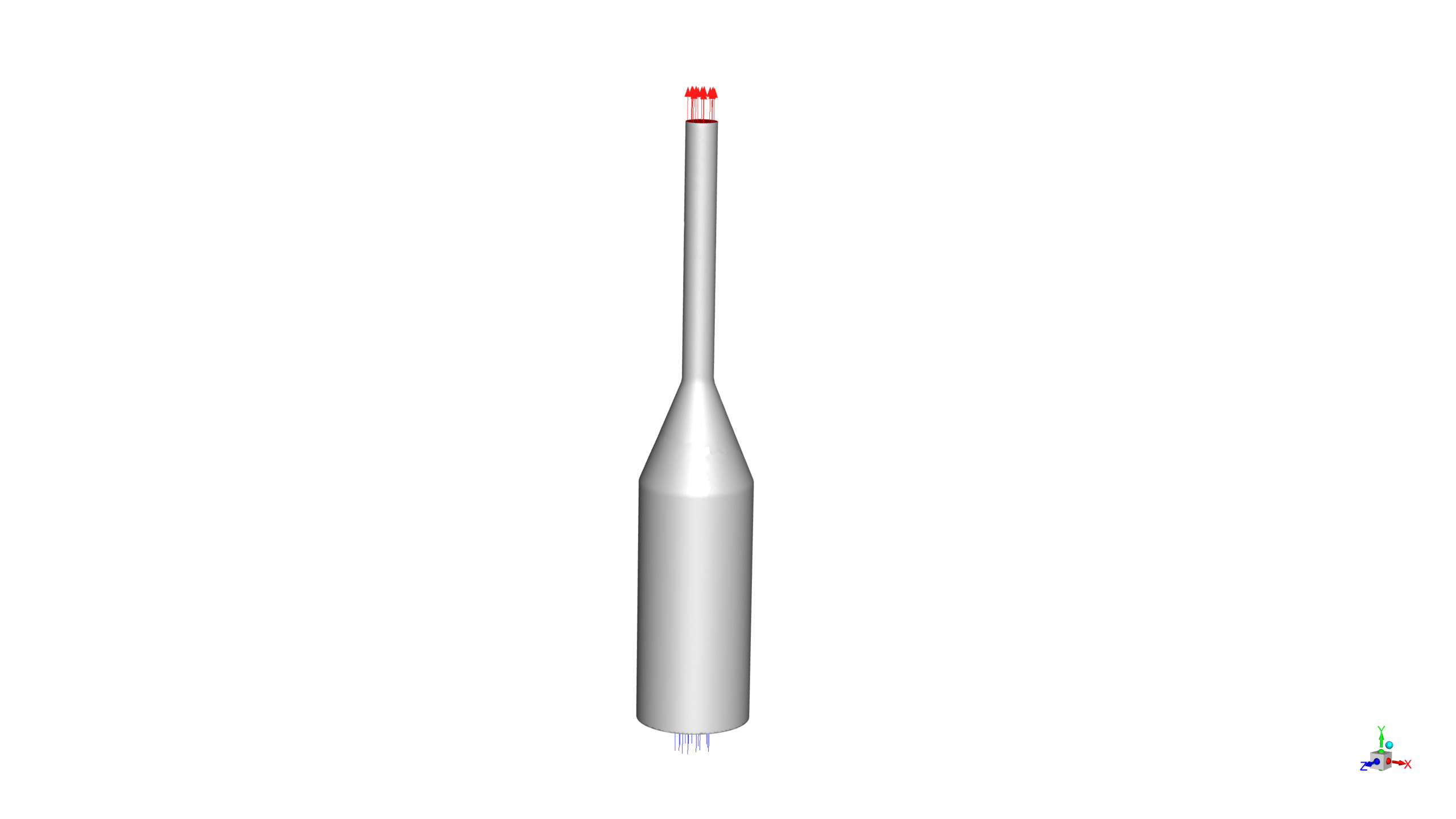
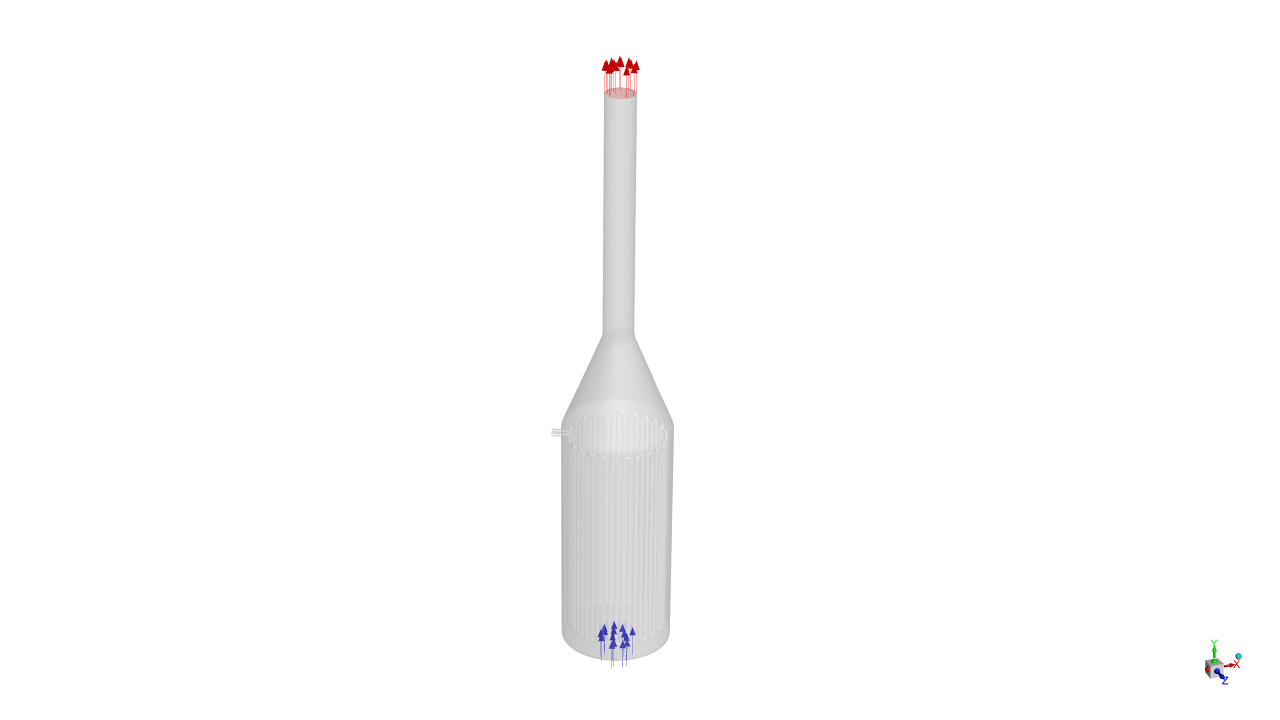
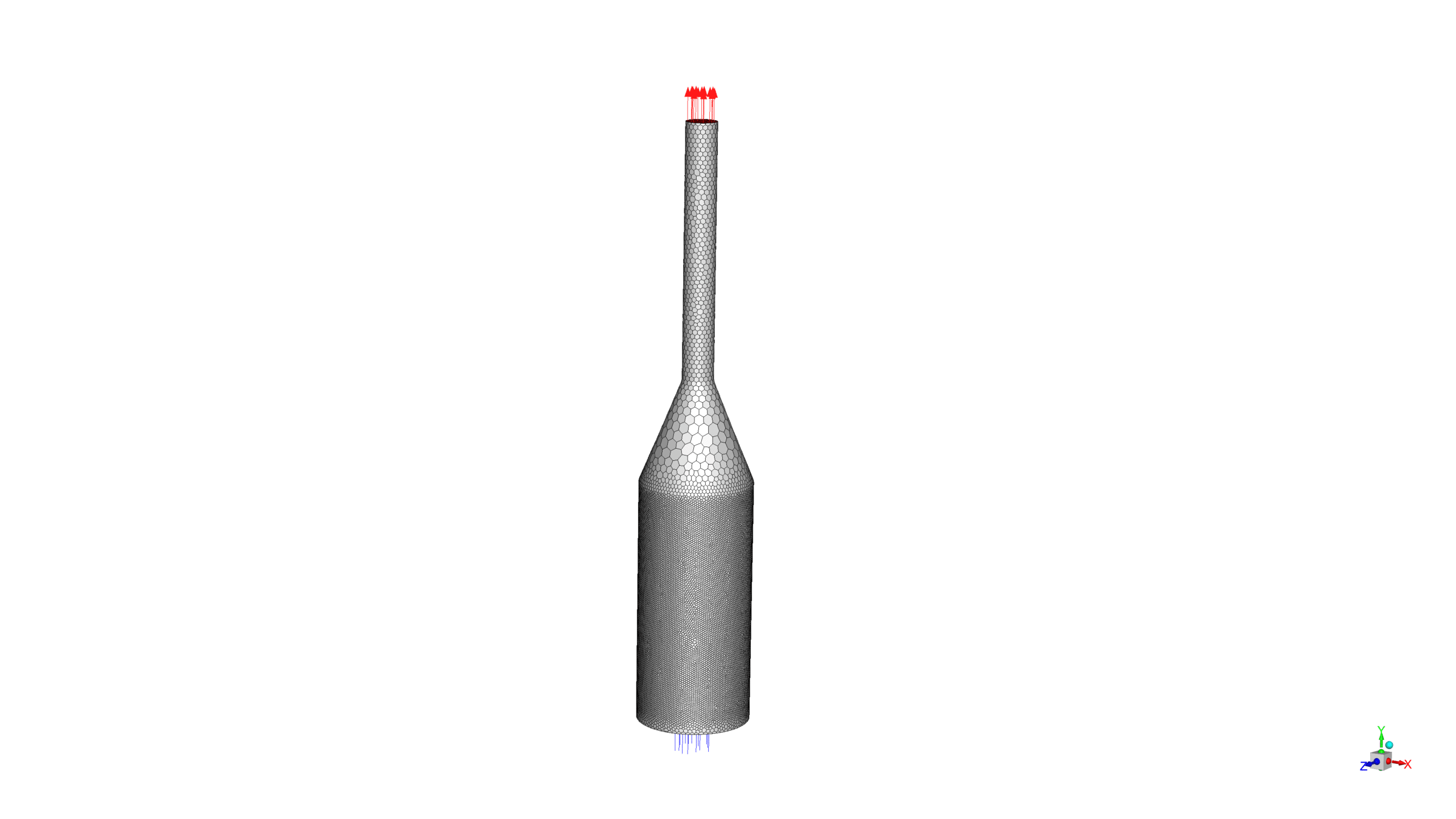
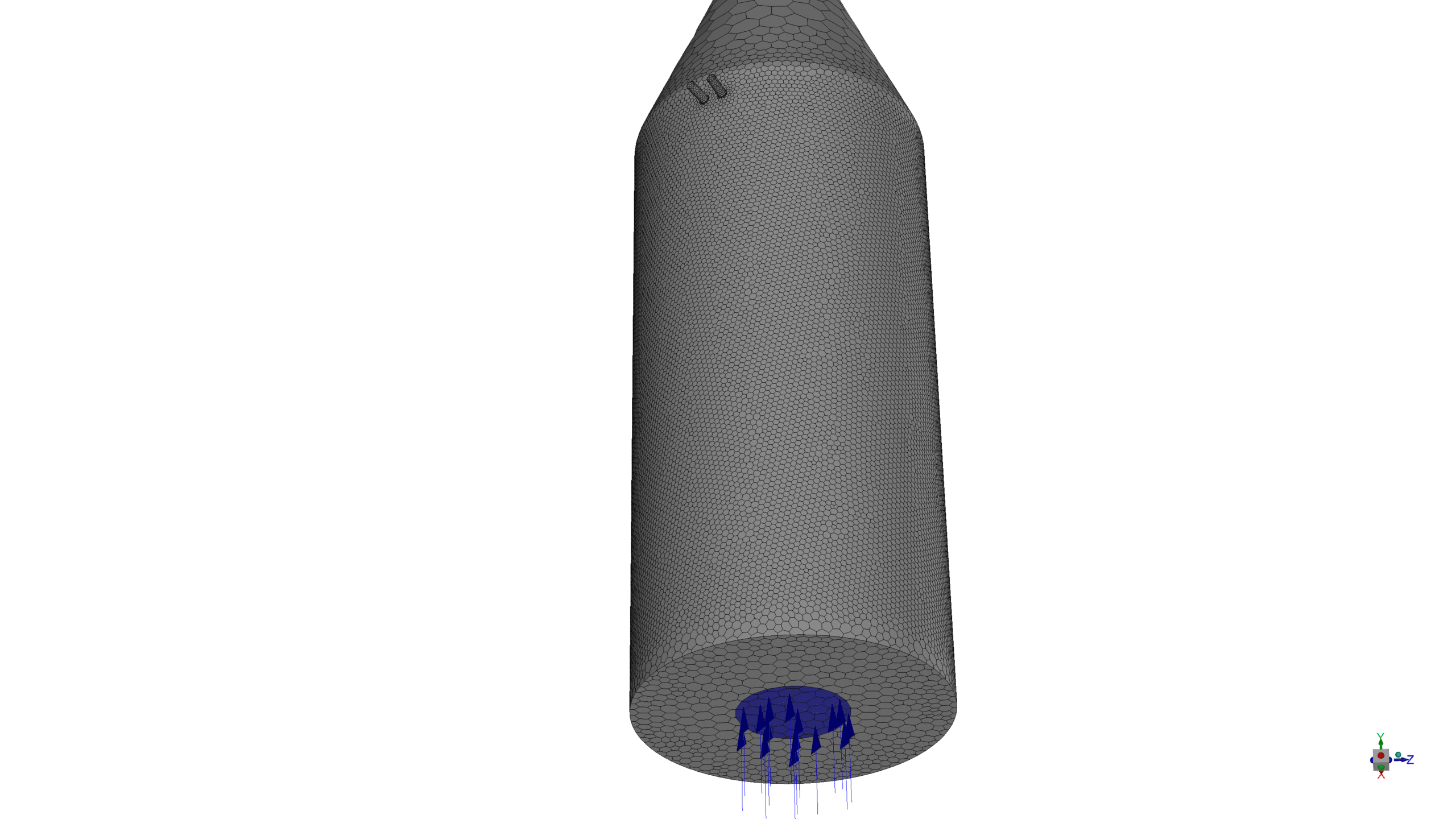
The geometry of the furnace was created in ANSYS Design Modeler, with a mesh of 1,039,748 polyhedra elements generated using ANSYS Meshing, providing sufficient resolution to capture the complex flow phenomena and chemical reactions.
Methodology
A steady-state, pressure-based solver was employed with the Realizable k-epsilon turbulence model and standard wall functions.
The Species Transport model was enabled to simulate the methane-air reaction, using the Eddy-Dissipation approach for turbulence-chemistry interaction.
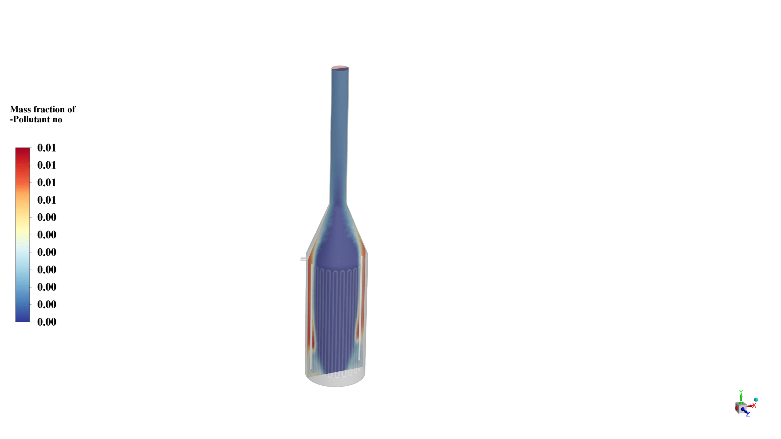
NOx production was also considered in the simulation.
Propane was introduced at the pipe inlet, while the methane-air reaction occurred within the furnace.
Results
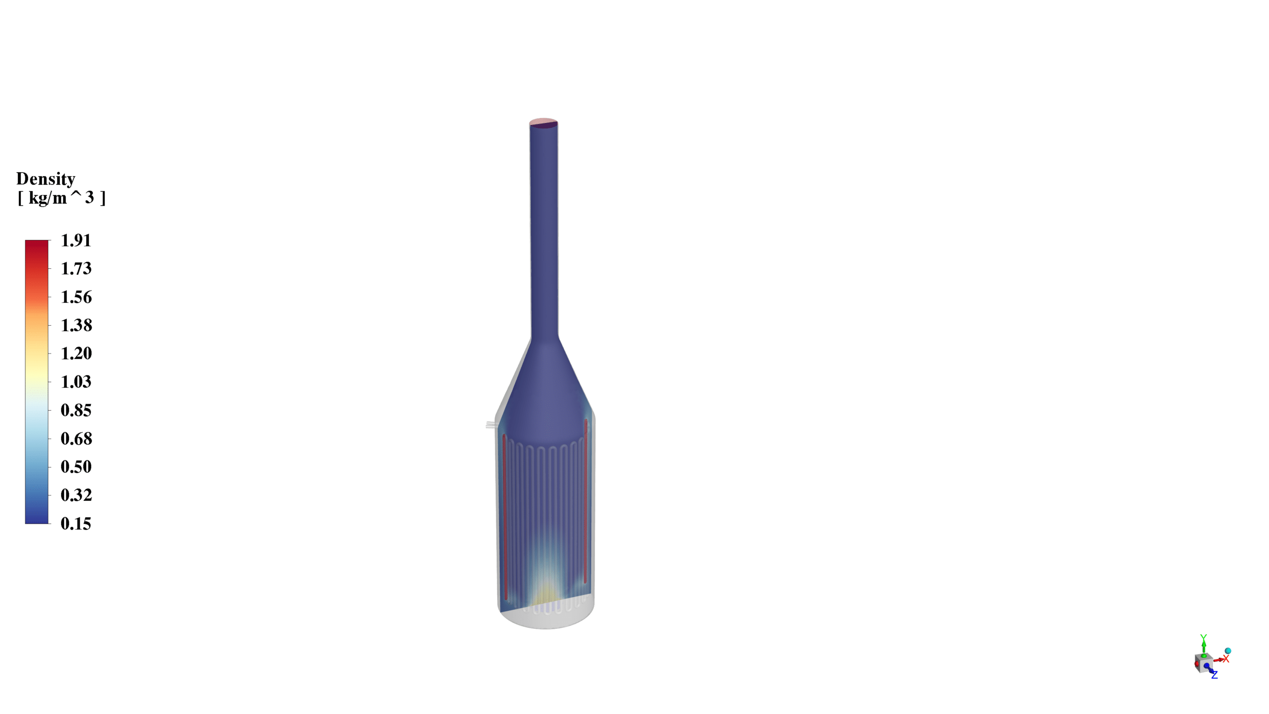
The simulation results provide valuable insights into the combustion process and species distribution within the furnace. The density contour reveals a stratified flow structure, with higher densities observed near the bottom of the furnace, likely due to the accumulation of heavier combustion products. This density gradient plays a crucial role in driving the natural convection within the furnace, influencing the overall flow patterns and mixing processes.
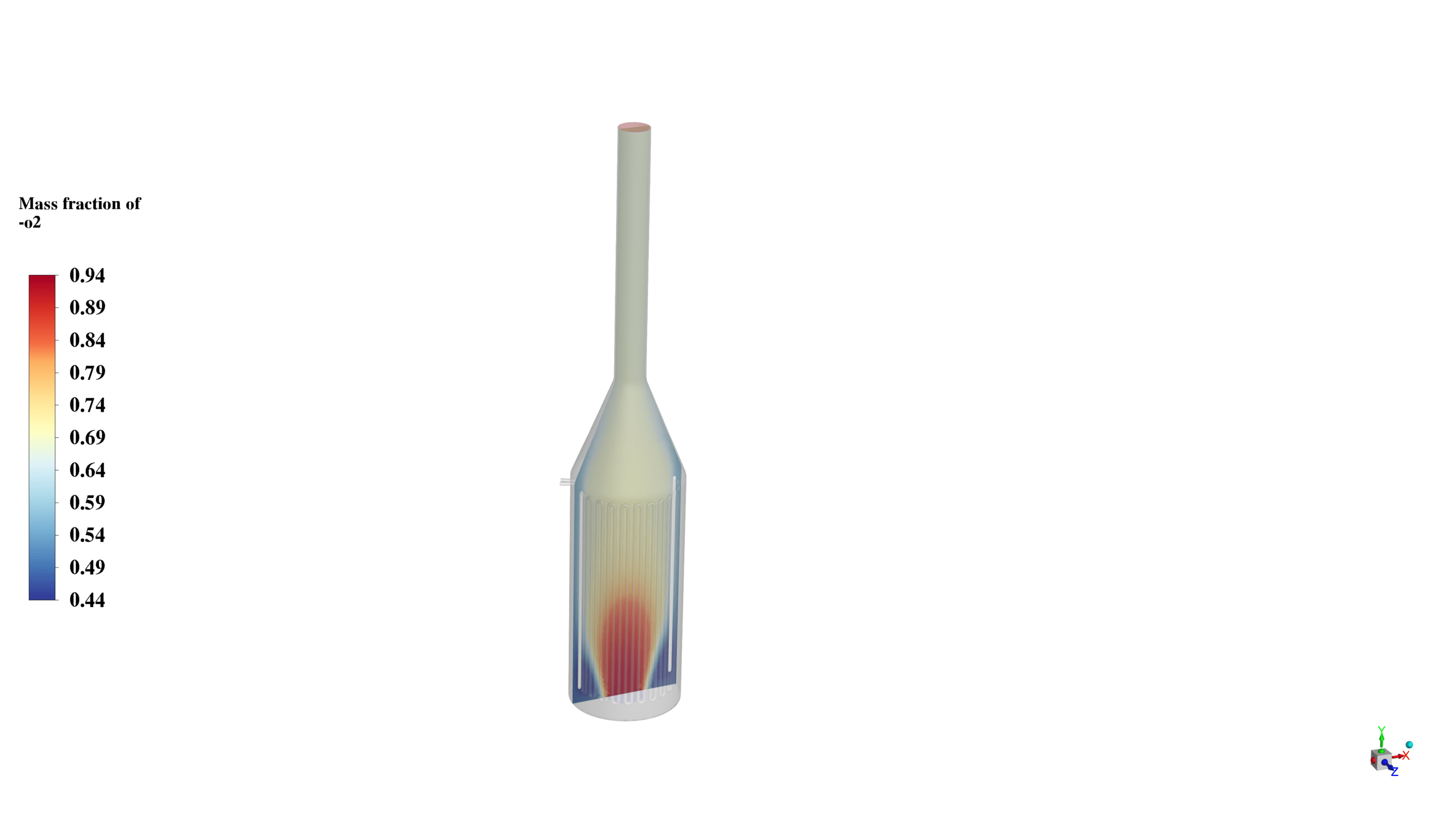
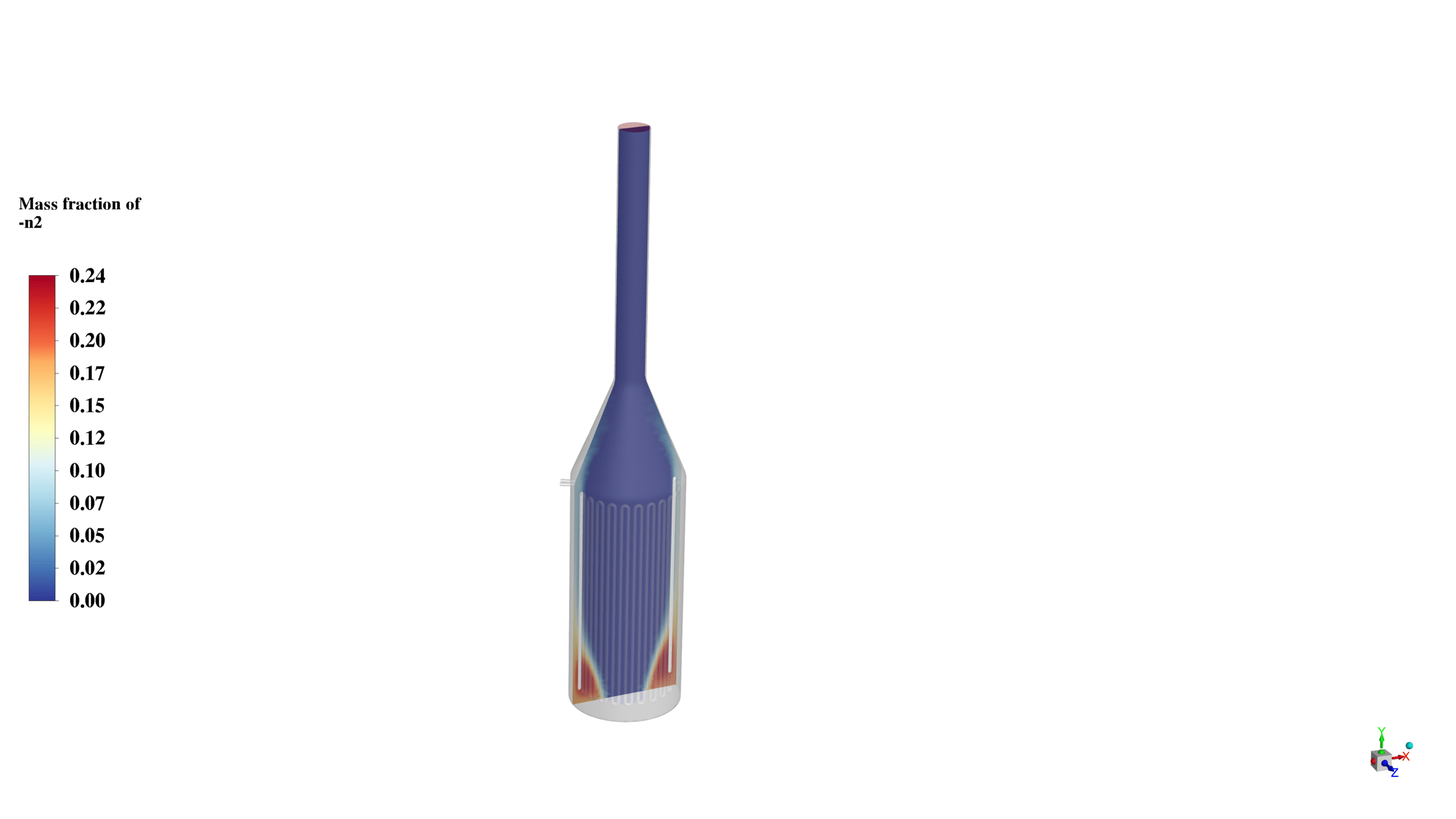
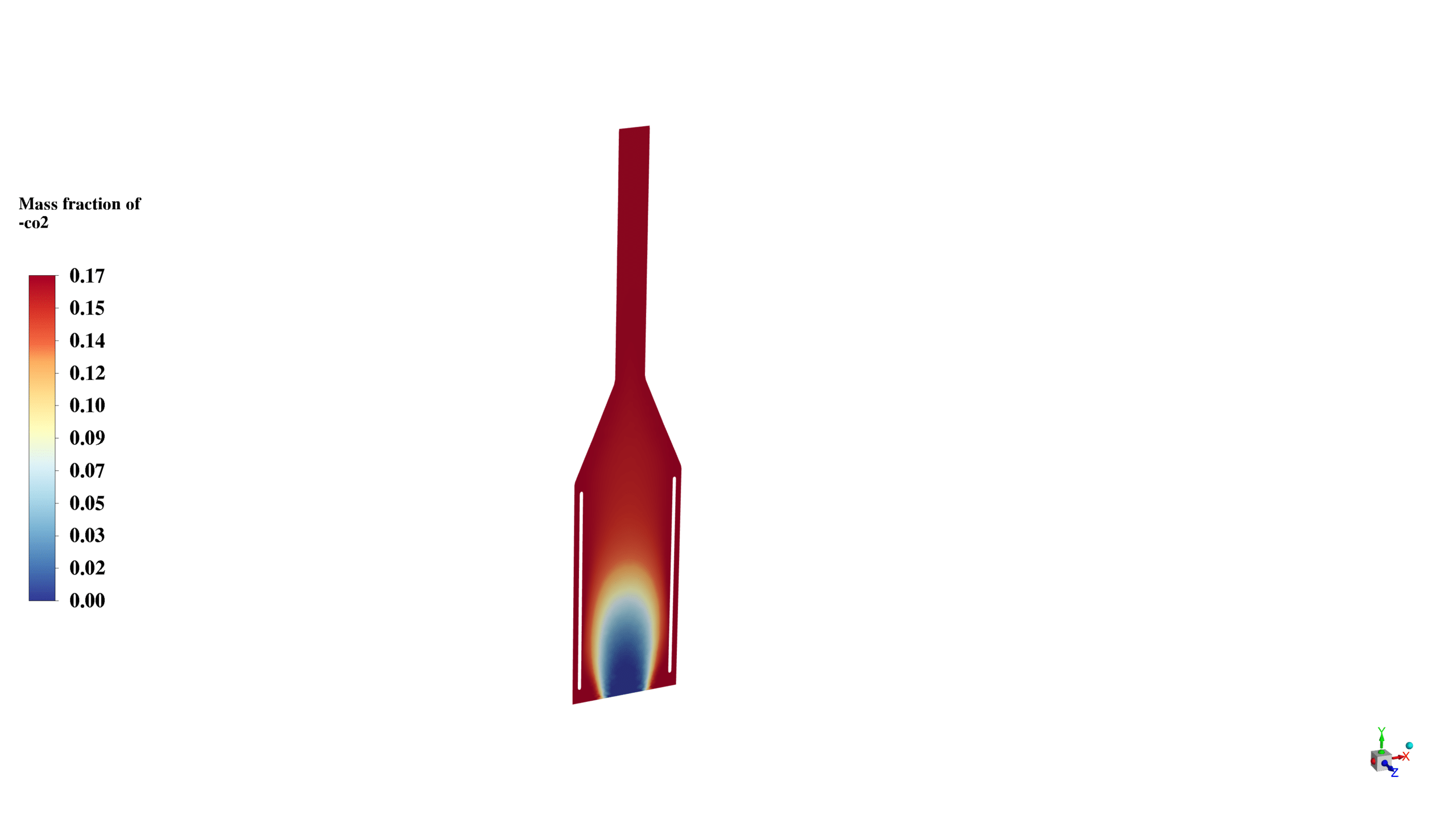
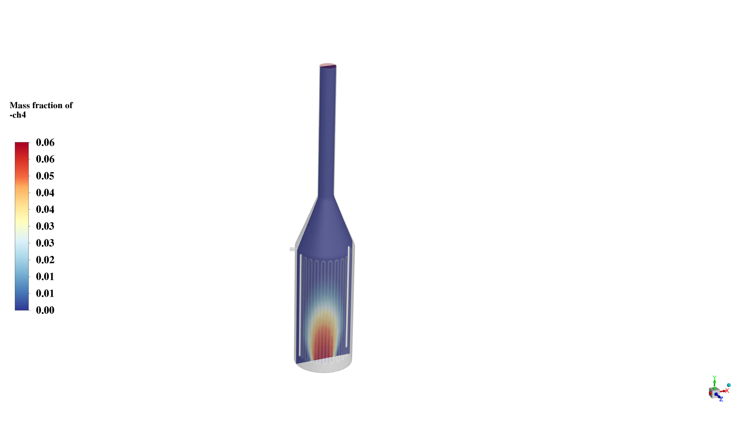
The mass fraction contours for CH4, CO2, N2, and O2 illustrate the complex interplay of reactants and products throughout the furnace. The CH4 contour shows a high concentration near the inlet, gradually decreasing as it reacts and moves upward. Conversely, the CO2 contour indicates higher concentrations in the upper regions of the furnace, consistent with the products of combustion rising due to buoyancy effects. The N2 and O2 distributions reflect the air intake and combustion processes, with O2 being consumed in the reaction zones.
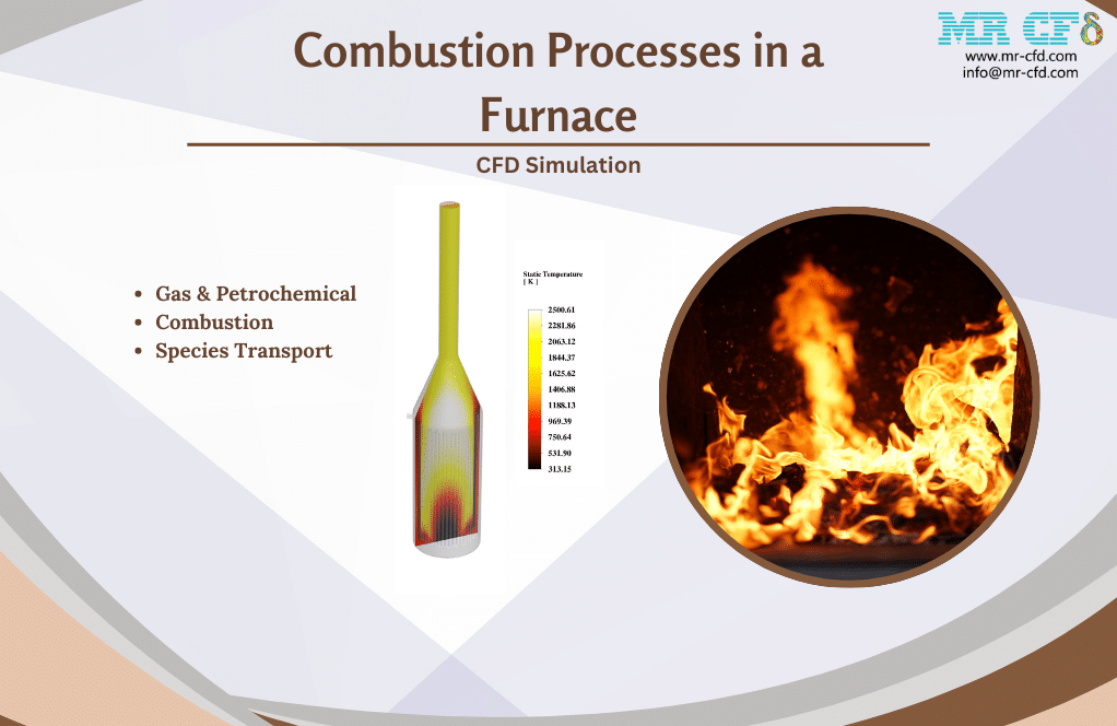
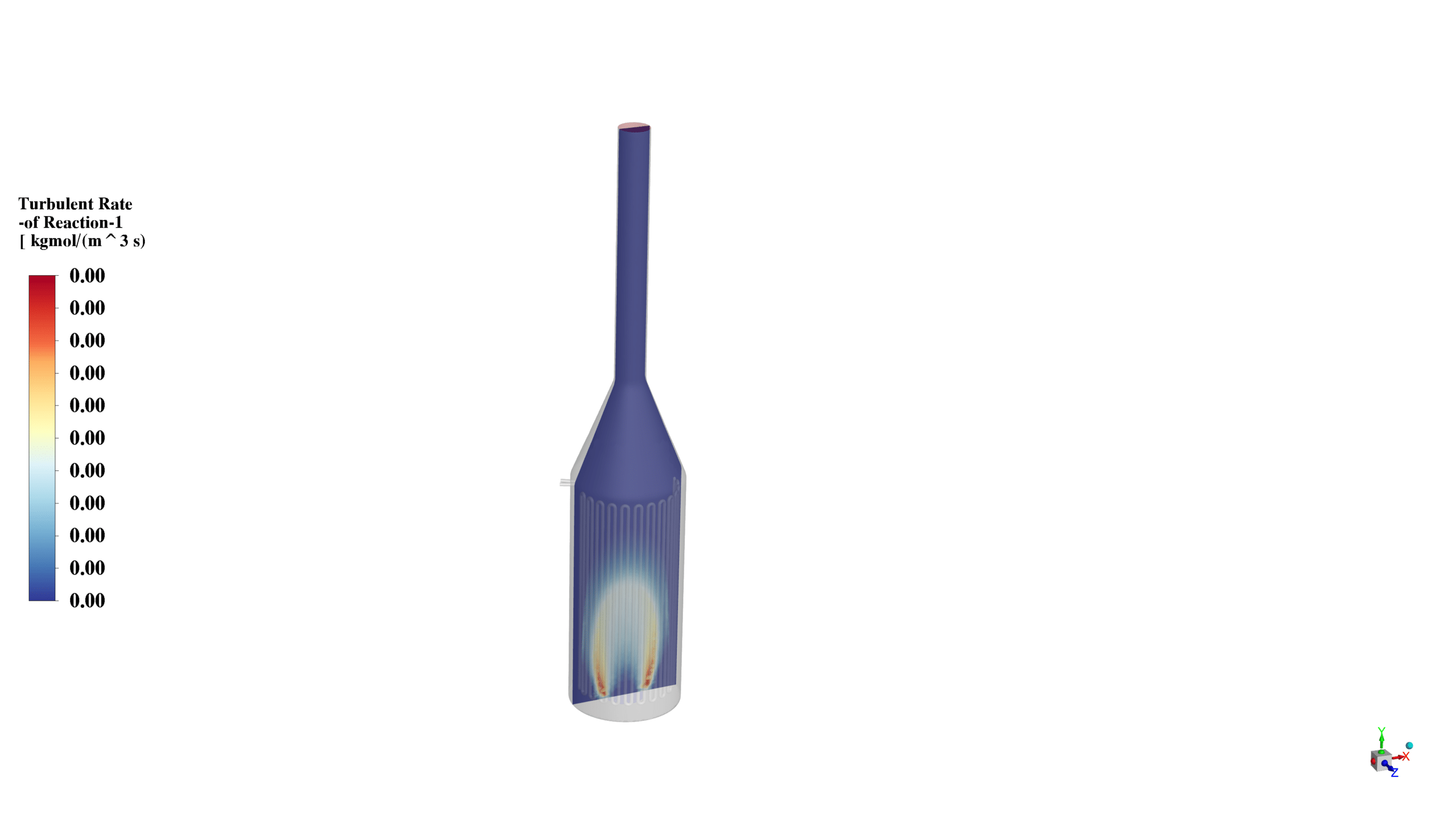
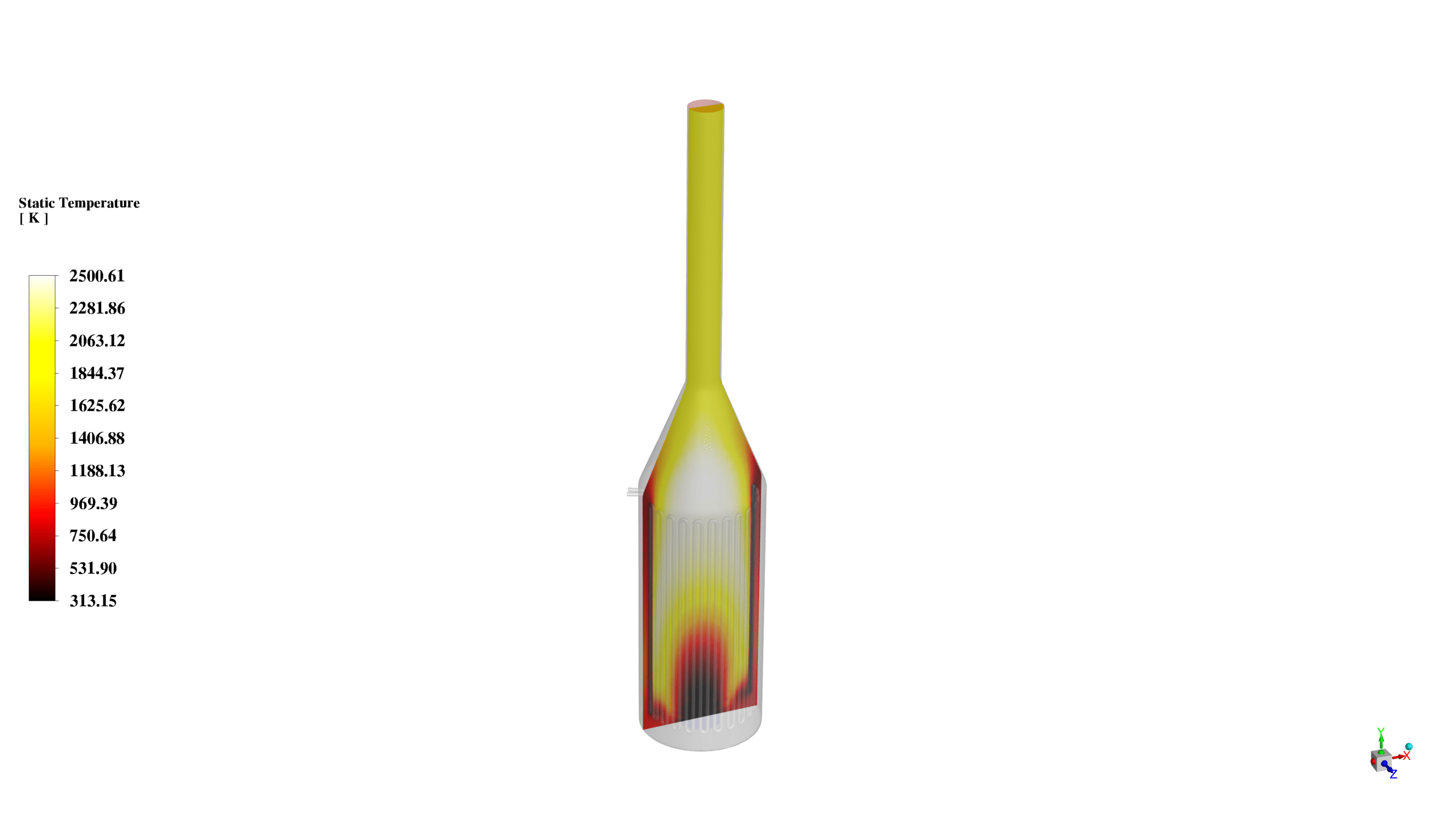
The static temperature contour reveals the thermal gradients within the furnace, with peak temperatures observed in the primary combustion zone. This temperature distribution is closely linked to the reaction rates and species concentrations, as evidenced by the turbulent reaction rate contour. The latter indicates areas of intense chemical activity, particularly near the fuel inlet where fresh reactants meet high temperatures. The velocity vectors at the inlet and outlet demonstrate the complex flow patterns within the furnace, including recirculation zones that enhance mixing and combustion efficiency. These results provide critical insights for optimizing furnace design, improving combustion efficiency, and minimizing pollutant formation.


Reviews
There are no reviews yet.