Compound Channel with Non-Prismatic Floodplain Simulation, Paper Numerical Validation
$240.00 $120.00 Student Discount
The present problem simulates a two-phase flow within a compound channel using ANSYS Fluent software. This simulation is based on the information from a reference article, “Application of the Shiono and Knight Method in compound channels with non-prismatic floodplains,” and its results are compared and validated with the results in the article.
Click on Add To Cart and obtain the Geometry file, Mesh file, and a Comprehensive ANSYS Fluent Training Video.To Order Your Project or benefit from a CFD consultation, contact our experts via email (info@mr-cfd.com), online support tab, or WhatsApp at +44 7443 197273.
There are some Free Products to check our service quality.
If you want the training video in another language instead of English, ask it via info@mr-cfd.com after you buy the product.
Description
Paper Description
The problem simulates a two-phase flow within a compound channel using ANSYS Fluent software. This simulation is based on the information from a reference article, “Application of the Shiono and Knight Method in compound channels with non-prismatic floodplains,” and we compare and validate its results with the results in the article. Most natural waterways (floodplains) consist of the main channel through which the natural flow of water moves. However, when the water flow increases, one or more flood layers are created in this main channel’s vicinity as a floodplain. Therefore, we can assume a channel whose cross-section does not consist of a basic geometric shape in this case.
These types of channels are called compound channels. The present simulation aims to investigate two-phase flow behavior, including water and air, in a compound channel. The compound channel geometry is based on the data in Figure 1-c of the reference paper. Since the present model consists of two phases of air and water, we use the multiphase Volume of Fluid model (VOF) in the Fluent software; So that the amount of surface tension force between the air and water is defined as 0.072 N.m-1. Also, since the water flow at the inlet section of the canal is only up to a certain height or level, the open channel flow model should be used. Thus, the height of the water level at the inlet section is equal to 0.0357143 m.
The water flow enters the channel at the inlet section with a flow rate of 17.9676 kg.s-1 (equivalent to a volume flow rate of 18 L.s-1); While the airflow in the inlet section is static and defined with zero mass flow rate.
Compound Channel Geometry & Mesh
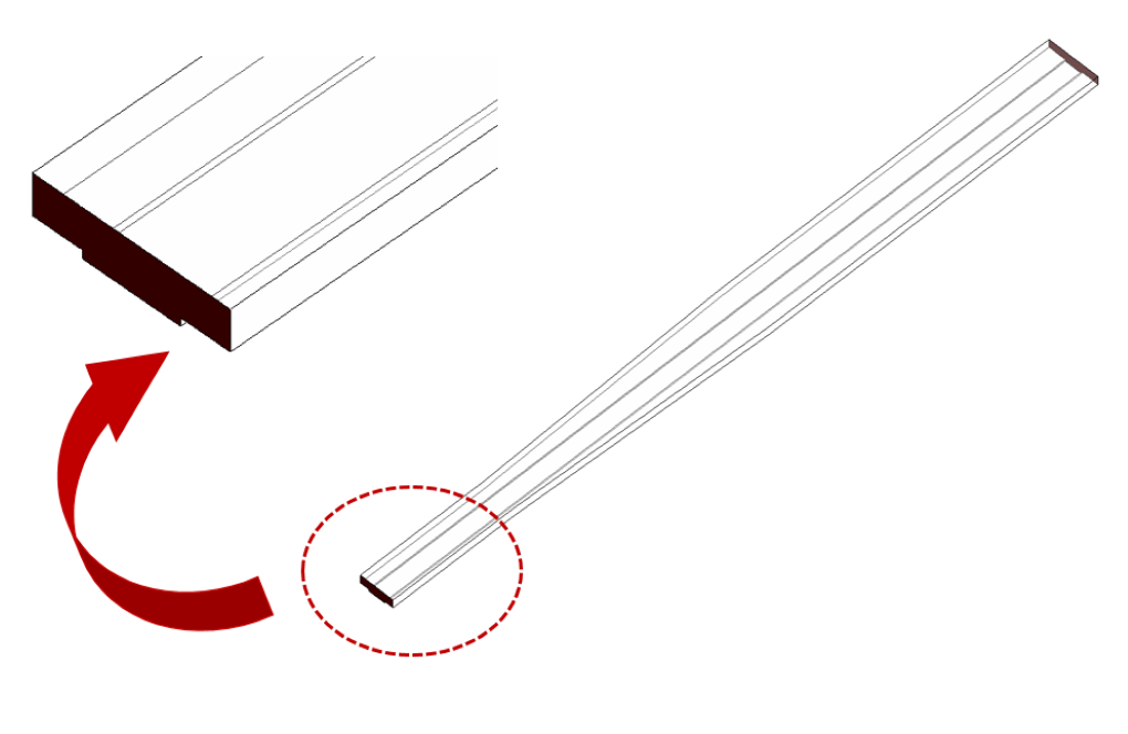
The present model is designed in three dimensions using Design Modeler software. These models are related to a convergent compound channel. The drawn model’s geometric characteristics are associated with the article’s third geometric design (Figure 1-c). This channel’s length equals 17 m and has a height or depth equal to 0.15 m. Also, since the channel is converging, its cross-sectional width at the channel’s entrance is equivalent to 1.198 m, and at the channel’s exit, it is equal to 0.798 m. Meanwhile, the canal’s main part in the canal route has a width of 0.398 m and a depth of 0.025 m.
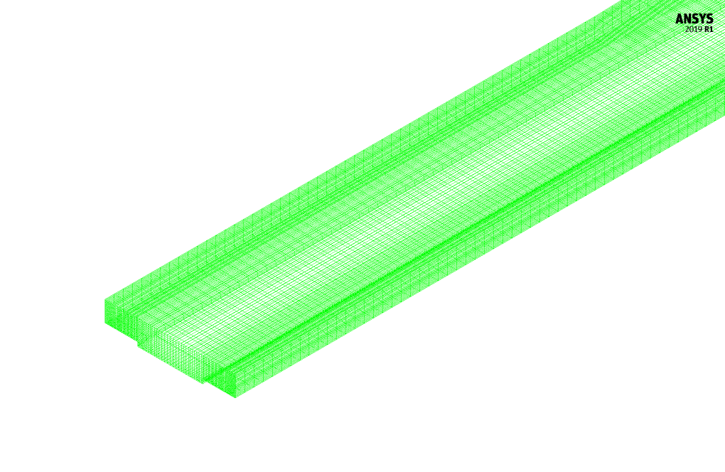
We carry out the meshing of the model using ANSYS Meshing software, and the mesh type is structured. The element number is 540000. The following figure shows the mesh.
Compound Channel CFD Simulation
We consider several assumptions to simulate the present model:
- We perform a pressure-based solver.
- The simulation is steady.
- The gravity effect on the fluid is equal to -9.81 m.s-2 along the Y-axis.
The following table represents a summary of the defining steps of the problem and its solution:
| Models | ||
| Viscous | k-epsilon | |
| k-epsilon model | standard | |
| near wall treatment | standard wall function | |
| Multiphase Model | VOF | |
| number of Eulerian phases | 2 (air & water) | |
| formulation | implicit | |
| interface modeling | sharp | |
| Boundary conditions | ||
| Inlet | Mass Flow Inlet | |
| free surface level for water | 0.0357143 m | |
| mass flow rate for water | 17.9676 kg.s-1 | |
| mass flow rate for air | 0 kg.s-1 | |
| Outlet | Pressure Outlet | |
| gauge pressure | 0 pascal | |
| Walls | Wall | |
| wall motion | stationary wall | |
| Methods | ||
| Pressure-Velocity Coupling | coupled | |
| pressure | body force weighted | |
| momentum | first order upwind | |
| volume fraction | Modified HRIC | |
| turbulent kinetic energy | first order upwind | |
| turbulent dissipation rate | first order upwind | |
| Initialization | ||
| Initialization methods | Hybrid | |
Results & Paper Validation
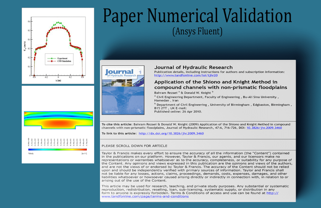
The present paper validation is based on the diagram in Figure 10-a of the mentioned article. This diagram is related to the profile of velocity value changes along the channel cross-section. This profile was obtained at a distance of 14 m from the channel entrance. Also, changes in the vertical velocity of the mixed flow and the line corresponding to the interface surface between the two water and air phases have been obtained.
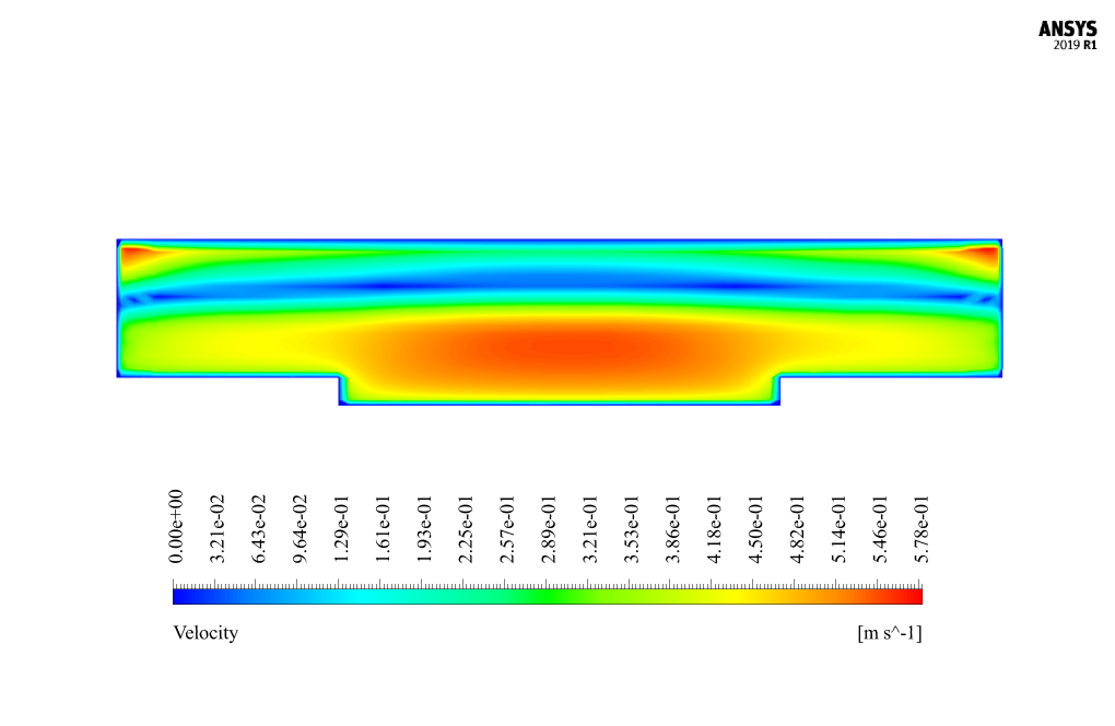
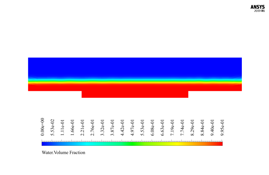
The iso-surface command can create a plane in which the volume fraction of water or air is 0.5 to find the line corresponding to the interface between the two phases because it can be assumed that the volume fraction of each of the two phases at the interface between the two phases is approximately equal to 0.5. Comparison and validation of the present numerical work results with the results of experimental work in the article are shown in Figure 3. These diagrams show that the amount of velocity in the space above the central part of the compound channel is higher than at other points.
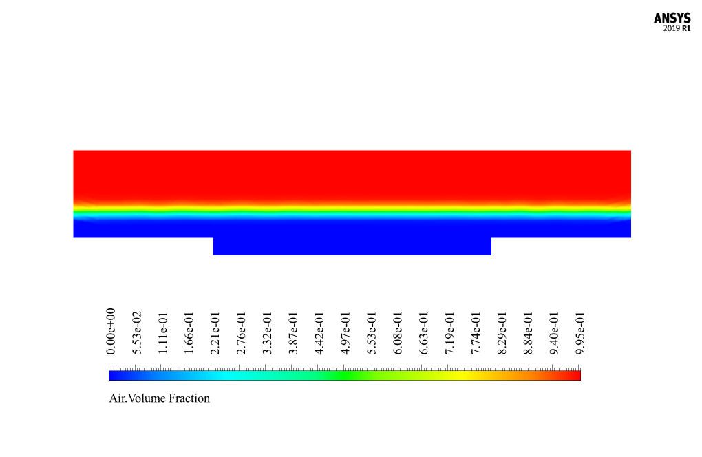
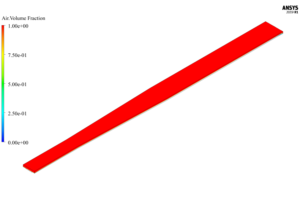
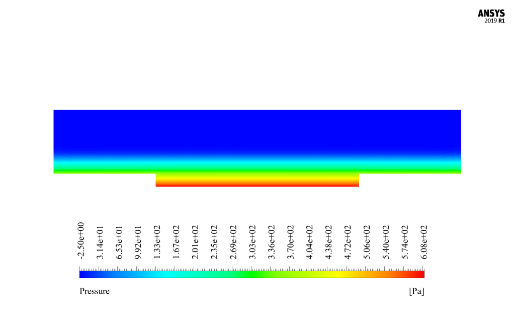
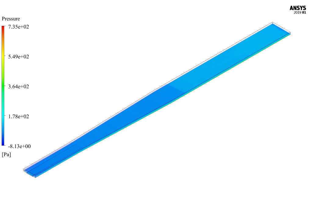
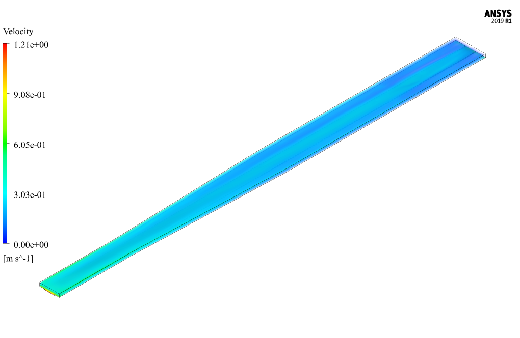
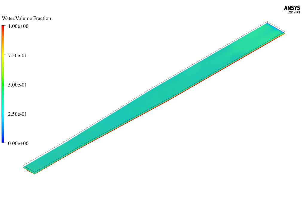
At the end of the solution process, two-dimensional contours related to the pressure, velocity, and volume fraction of each air and water phase are obtained. Two-dimensional contours are obtained in a section parallel to the channel inlet section (X-Y plane) and at a distance of 14 m from it.


Tianna Fisher MD –
How can I validate the results of this simulation?
MR CFD Support –
The results of this simulation can be validated by comparing them with experimental data or results from other reliable sources. This can help you ensure the accuracy of the simulation and build confidence in its predictions.
Walter Hand –
How can I validate the results of this simulation?
MR CFD Support –
The results of this simulation can be validated by comparing them with experimental data or results from other reliable sources. This can help you ensure the accuracy of the simulation and build confidence in its predictions.
Heather Kassulke –
I appreciate the dedication to accuracy and validation in this simulation.
Anika Cummerata –
Can this simulation handle different geometries of the main channel and the floodplain?
MR CFD Support –
Absolutely! The simulation can be adapted to handle different geometries of the main channel and the floodplain by changing the geometry in the simulation setup. This makes it a versatile tool for studying various types of compound channels.
Vincent Pfannerstill –
What a fantastic learning tool provided by MR CFD Company! The outcome of my simulations matched perfectly with the validation reference. Not only did it bolster my understanding of compound channel simulations, but utilizing the VOF model for two-phase flow made complex concepts much more digestible. I appreciate the structured mesh approach as it lent to more accurate predictions so crucial in Fluid Dynamics studies!
MR CFD Support –
Thank you for your positive feedback! We are thrilled to hear that our simulation product has effectively contributed to your understanding of compound channel and two-phase flow simulations. It’s excellent to know that the VOF model and our presentation was helpful. If there’s anything more we can do for you or any other products you may be interested in exploring, please let us know!
Mr. Jabari Borer –
Every aspect of this product sounds quite technical. I’m curious about the turbulence modeling. Could you please share how does the k-epsilon model contribute to the accuracy of this CFD simulation for compound channels?
MR CFD Support –
In this CFD simulation of a compound channel, the k-epsilon model provides insights into the turbulence characteristics of the flow. Its use allows for a standard wall treatment that considers the near-wall turbulence, crucial for accurately predicting the distribution of velocity and pressure along the cross-section of the channel, especially when the channel geometry is non-prismatic and complex. The k-epsilon model helps predict eddy viscosity distributions, making it possible to identify areas of high and low flow convergence beatly and accurately throughout the simulation.
Aurelie Armstrong –
I am highly impressed with the level of detail in the validation of the simulation compared to the reference paper. Can you point out anything in your findings that particularly stood out in comparison to the experimental data presented in the article?
MR CFD Support –
Thank you for your compliments. I’m delighted that you appreciate the diligence put into ensuring the accuracy of our simulations. In our findings, the simulation precision captured at 14 meters from the channel’s inlet was particularly noteworthy. Our computational model echoed the experimental data successfully, showing velocity distributions and water-air interface locations with remarkable similarity. This attention to detail reinforces the validity of our simulation techniques and model calibration capabilities.
Callie Pollich –
Thanks to the team for a detailed and comprehensive explanation of the simulation process. It’s amazing to see complex floodplain interactions being modeled and understood through CFD.
MR CFD Support –
We’re thrilled to hear that you’re impressed with the level of detail in our simulation and explanation! Understanding floodplain dynamics is indeed complex, and using CFD to model these interactions is crucial. Thank you so much for your kind words and support!
Dr. Hayley Hammes IV –
I’m curious about the air phase in the simulation. How is the zero mass flow rate for air handled and what’s its purpose in this CFD study relating to the compound channel flow dynamics?
MR CFD Support –
In this simulation, the zero mass flow rate for the air is used to represent a static air phase above the water flow in the inlet section of the channel. This condition is set as part of the Open Channel flow model and allows for the examination of the air-water interface and its impact on the flow dynamics within the channel. The static air phase helps to isolate the behavior of the flowing water and observe how it reacts with a non-moving air body, simulating realistic environmental conditions.
Prudence Ullrich II –
The learning materials were great! All the steps were clearly outlined, from setting up the models in ANSYS to validating the results against the article. The diagrams included were quite helpful in understanding the flow behavior, especially how air and water phases interact in the compound channel.
MR CFD Support –
Thank you for your positive feedback! We’re delighted to hear that you found the materials well-structured and the diagrams insightful for grasping the details of the two-phase flow simulation. If you have any further questions or need more information, please feel free to contact us.
Lucy Hirthe V –
The simulation describes a complex two-phase flow scenario. Does the included data help to understand what specific kind of validation is done against the experimental data mentioned in the paper?
MR CFD Support –
Yes, the described simulation provides detailed information about the validation process. The validation is based on comparing simulated velocity profiles along the channel cross-section with those from experimental data in the referenced paper. It illustrates how closely the simulation matches real-world observations, thereby confirming the model’s accuracy.
Kathlyn Bailey –
How accurate is this simulation in predicting the behavior of a compound channel with a non-prismatic floodplain?
MR CFD Support –
This simulation uses advanced numerical methods and accurate models of the compound channel and the floodplain to provide a highly accurate prediction of their behavior. However, like all simulations, it should be used in conjunction with other engineering analyses and not as a sole decision-making tool.
Nicole Conn –
Great detail in the simulation process! Are the results of velocity profiles along the channel cross-section validated against experimental data, and if so, how closely do they match?
MR CFD Support –
Thank you for recognizing the details in the simulation project! Yes, the velocity profiles along the channel cross-section are indeed validated against experimental data from the reference article. They show good agreement, with comparable profile shapes and magnitudes, confirming the accuracy of the CFD simulation. However, some minor discrepancies due to model simplifications or measurement uncertainties in the experimental setup are expected, which is common in numerical validations.
Afton Reinger II –
Is the influence of sediment or debris on the flow within the compound channel taken into account in this simulation, given it can be a factor in natural waterways?
MR CFD Support –
In the simulation detailed in the product description, sediment or debris is not explicitly considered. The focus is on two-phase flow behavior using the Volume of Fluid (VOF) model to study the interaction between water and air in a compound channel, following the guidelines from the referenced paper on which the numerical validation is based.
Octavia Kutch III –
What are some of the challenges I might face when setting up a simulation like this on my own, especially considering the interface between water and air?
MR CFD Support –
Setting up a simulation like the compound channel with non-prismatic floodplains can be challenging due to the complex interactions between phases — especially at the water and air interface. Challenges include accurately capturing the interface with sufficient mesh resolution, setting the correct volume fraction for VOF modeling to track the interface, and ensuring numerical stability for convergence. Correctly defining boundary conditions and calibrating the model to experimental data can also be complex, requiring a deep understanding of both the physics and numerical methods involved.
Dr. Julien Harber –
What are the benefits of simulating a compound channel using CFD instead of physical modeling?
MR CFD Support –
Simulating a compound channel using CFD allows for detailed analysis of the flow behavior in complex geometries that would be difficult and costly to replicate in physical models. It also offers the ability to easily manipulate the model parameters for sensitivity analysis and optimize the channel design without the need for constructing multiple physical prototypes.
Mr. Dillan Olson –
Noticing the structured mesh and attention to boundary conditions, were there any special considerations to ensure the mesh could accurately capture the flow gradient changes, especially considering the channel’s non-prismatic nature?
MR CFD Support –
The construction of a structured mesh for the simulation of flow within non-prismatic compound channels included particular attention to ensuring that the mesh was sufficiently refined around areas of interest where gradients might be steeper or more complex. The resolution had to be high enough to accurately capture these flow gradients while avoiding excessive computational costs. Additionally, the boundary conditions were specified to match experimental conditions closely, focusing on achieving real-world accuracy for validation purposes with the establiched literature.
Rosamond Thompson –
The explanation was superb. The compound channel project looked intense, but the results explained in your description indicate an in-depth simulation faithful to the reference paper. Well-done!
MR CFD Support –
Thank you for your kind words! We’re thrilled to hear that the description of our compound channel simulation was clear and that the in-depth analysis met your expectations. If you have any further questions or need more information about our simulations, feel free to ask. We’re here to help!
Jennifer Rice IV –
Thank you for the detailed information on simulating compound channels with ANSYS Fluent based on that research paper. The methodology for validation is thorough, and the meshing details assure quality results. How were the numerical results compared to the experimental data specifically addressed in the paper?
MR CFD Support –
In the product’s description, it is noted that the comparison and validation of the numerical results against the experimental data were conducted using the velocity profile diagram shown in Figure 10-a of the mentioned research paper. The velocity profile was taken at a distance of 14 meters from the channel entrance and included data such as mixed flow vertical velocity and location of the water-air interface. The iso-surface command was mentioned to assist in locating the interface by setting the volume fraction between the two phases to 0.5. This careful analysis helps ensure that the simulation results are accurate when compared to the real-world data presented in the article.
Prof. Solon Connelly –
I learned a lot from the Compound Channel with Non-Prismatic Floodplain Simulation tutorial! The content was thorough and well-explained. How well did the simulation results correspond with the article’s findings for velocity profiles?
MR CFD Support –
Thank you for your positive feedback on our Compound Channel simulation tutorial! We’re thrilled to hear that the material was comprehensive and clear. To answer your question, the simulation results showed a good correspondence with the article’s findings for velocity profiles. The comparison revealed that the numerical simulation accurately captured the higher velocity magnitudes in the space above the central part of the compound channel, similar to the experimental results presented in the article. This validation showcases the precision and reliability of our CFD modeling in replicating complex fluid behaviors in compound channels.
Lonzo Effertz MD –
I found the information about setting up the model fascinating. Could you further explain how you verify and validate the results with the reference article’s data?
MR CFD Support –
Certainly! After completing the simulation, we gather the results, specifically the velocity profile along the channel cross-section. We then directly compare this simulation data with the velocity profile graph from Figure 10-a in the reference article. By creating iso-surfaces where the water and air volume fraction is 0.5, we also approximate the interface between the two phases. The correspondence of these profiles, the positioning of the phase interface line, and other flow characteristics with those from the article’s experimental results serve as the basis of our verification and validation process. We carefully examine both qualitative and quantitative agreements in flow patterns, velocity magnitudes, and phase distributions to ensure our simulation accurately reflects the documented case.
Brycen Reilly –
This is a magnificent accomplishment in CFD simulation, especially in terms of comparing and validating against experimental data. Can you provide more insights on how you ensured the accuracy between your simulation results and the experimental results from the paper? It feels rewarding to see such advanced techniques used to enhance our understanding of real-world scenarios.
MR CFD Support –
We appreciate your positive feedback on our simulation work! To ensure accuracy between our simulation results and the experimental results from the paper, we meticulously followed the setup details and conditions presented in the reference article. We used the same geometrical parameters and boundary conditions, and our mesh generation was finely tuned to capture the nuances of the complex flow within the compound channel. Also, by employing the Volume of Fluid model, we were able to precisely track the interface between air and water phases. Verification techniques like grid independence tests and sanity checks on simulation convergence were also implemented. The use of the iso-surface command at the volume fraction of 0.5 allowed an accurate depiction of the interface profile. These steps collectively contributed to the successful validation of our CFD results. Thank you once again for recognizing our efforts.
Raegan Skiles –
I had a great time diving into the details of the simulation comparing to the Shiono and Knight method’s article. Could you shed a light on how the VOF model is calibrated to capture the air-water interface so accurately?
MR CFD Support –
In our simulation, we’ve utilized the Volume of Fluid (VOF) model to accurately capture the interface between air and water. The model is calibrated through careful selection of grid resolution, understanding physical properties of both phases, such as density and viscosity, and implementing appropriate surface tension settings between the two fluids. The ‘iso-surface’ method is used to distinguish between phases accurately by setting up a plane where the volume fraction of water or air is 0.5, facilitating a clear definition of the air-water interface required for an accurate simulation.