Compressible Flow in a Bent Pipe CFD Simulation
Free
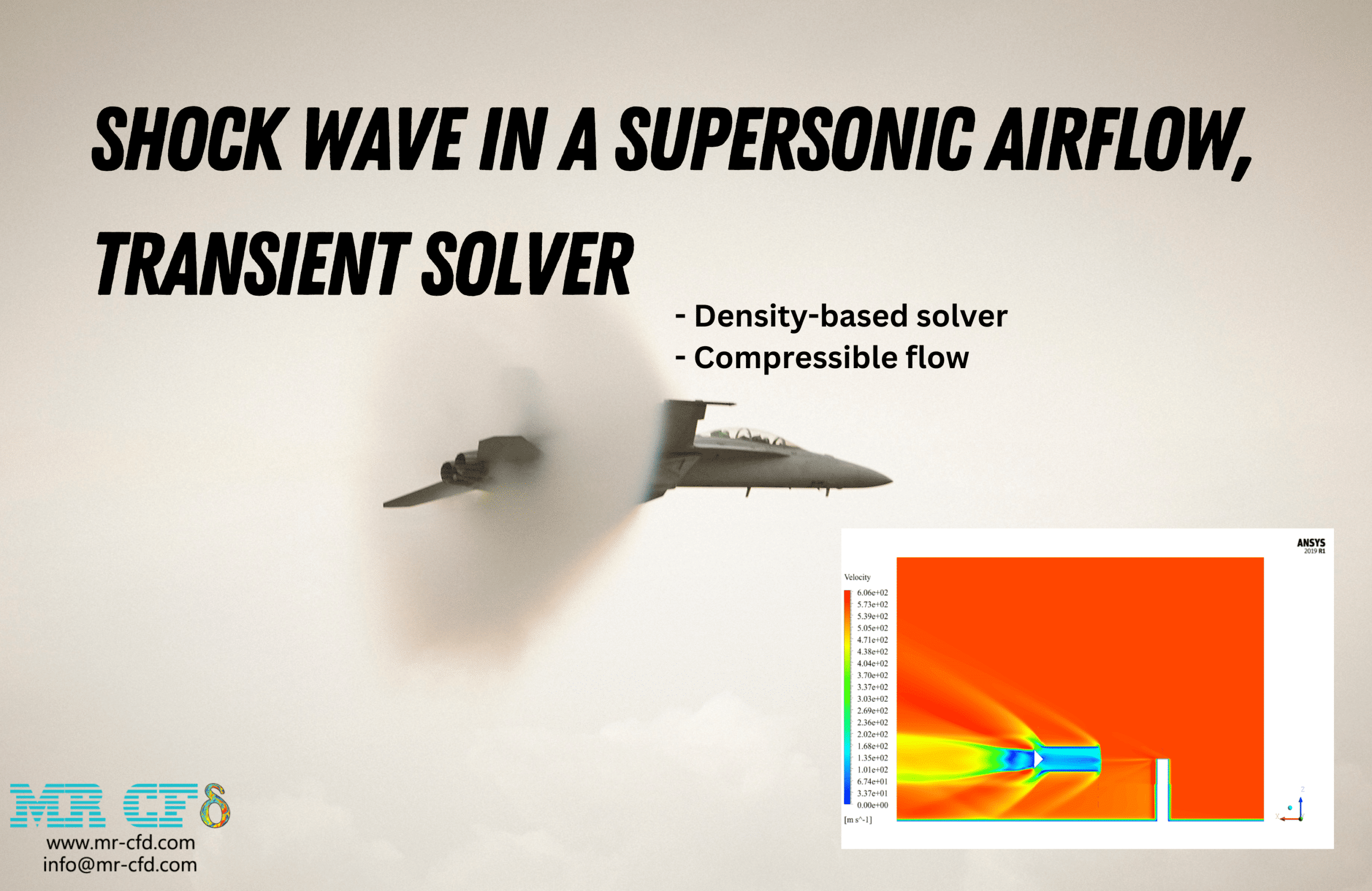
- The present CFD Project simulates Compressible Flow in a Bent Pipe via ANSYS Fluent software.
- We modeled the geometry using ANSYS Design Modeler software and created the mesh using ANSYS Meshing software.
- The number of cells after refinement is 1,450,983.
- The solution has been solved Transiently.
- The solver is Density-Based to capture the compressibility of the flow.
To Order Your Project or benefit from a CFD consultation, contact our experts via email (info@mr-cfd.com), online support tab, or WhatsApp at +44 7443 197273.
There are some Free Products to check our service quality.
If you want the training video in another language instead of English, ask it via info@mr-cfd.com after you buy the product.
Description
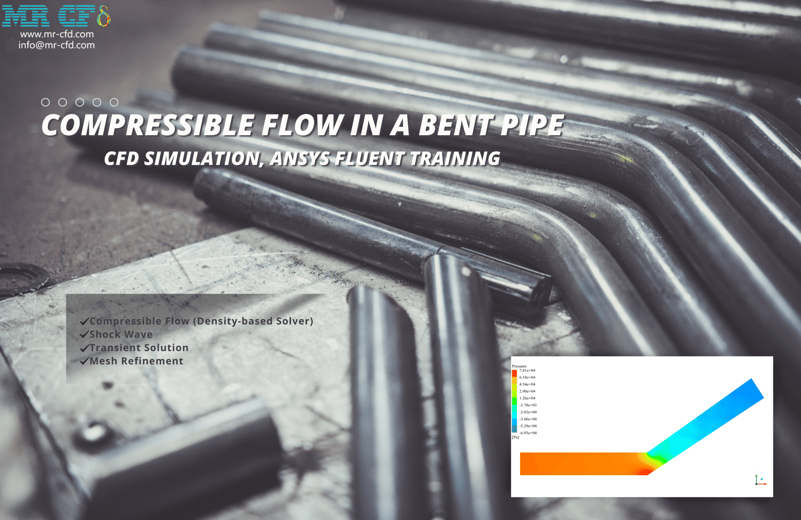
Compressible Flow in a Bent Pipe CFD Simulation, ANSYS Fluent Training
Description
In this project, the compressible flow inside a bent pipe is simulated, and the shock wave is investigated. 5 Celcius degree air enters through the pipe inlet with a 0.9 Mach number. The extreme pressure gradient causes a shock wave. The mesh grid needs to be refined to capture flow ideally at high gradient zones. Therefore, we can hire the gradient adaption option in ANSYS Fluent software.
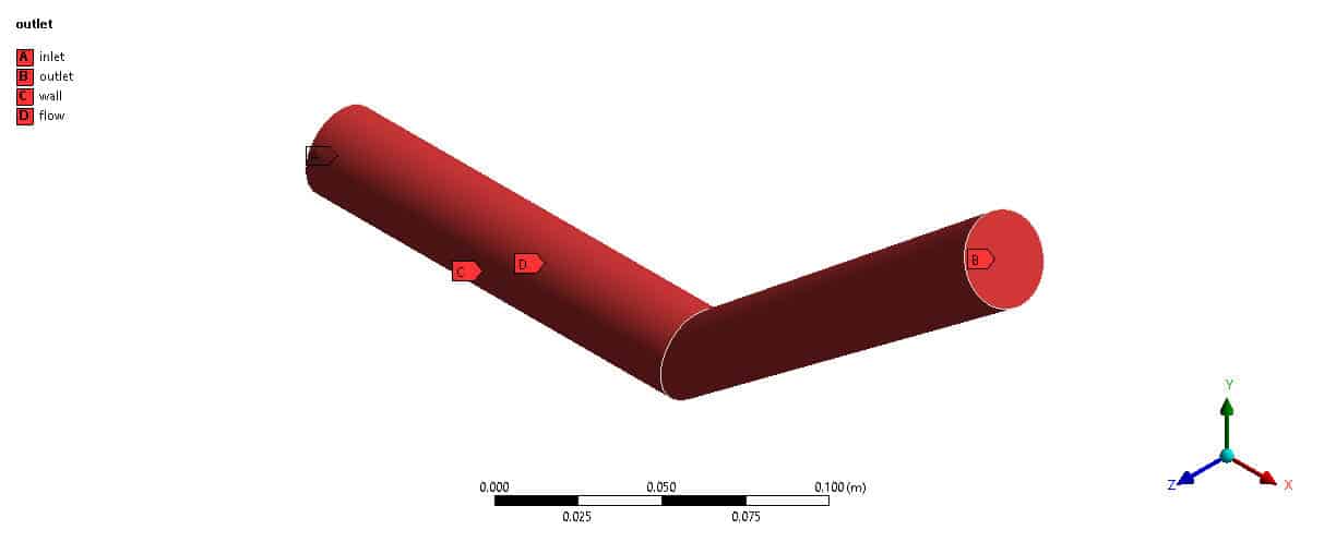
The 3D geometry was generated in Design Modeler software. A bent pipe with a 3cm diameter was sketched. In addition, an unstructured mesh grid was carried out using ANSYS Meshing software, and overall, 191,479 elements were generated. After hiring the gradient adaption option, the mesh grid was refined and reached 1,450,983 elements.
This CFD project is the 6th episode of the ANSYS Fluent General Training Course.
Methodology: Compressible Flow in a Bent Pipe
This simulation focuses on using a Density-based solver. Also, the simulation has performed in Transient form.
Conclusion
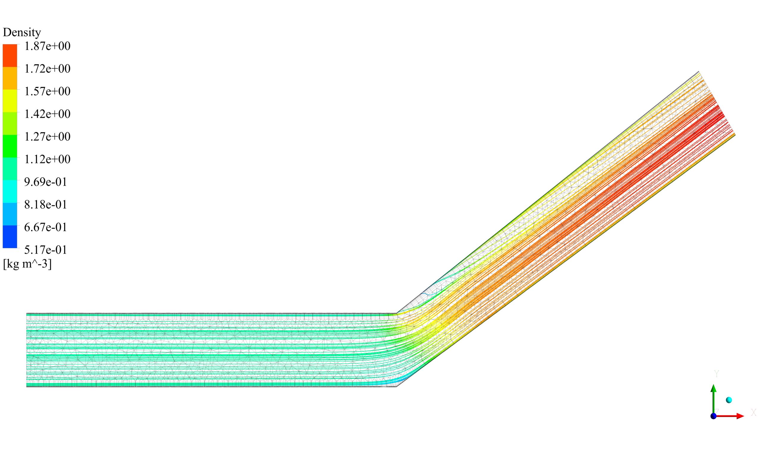
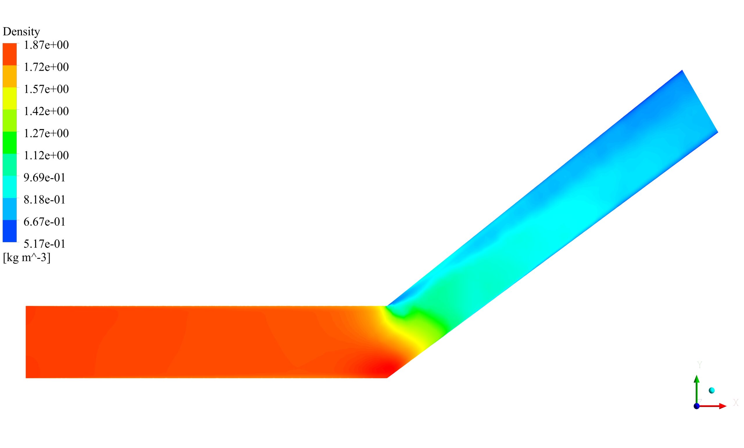
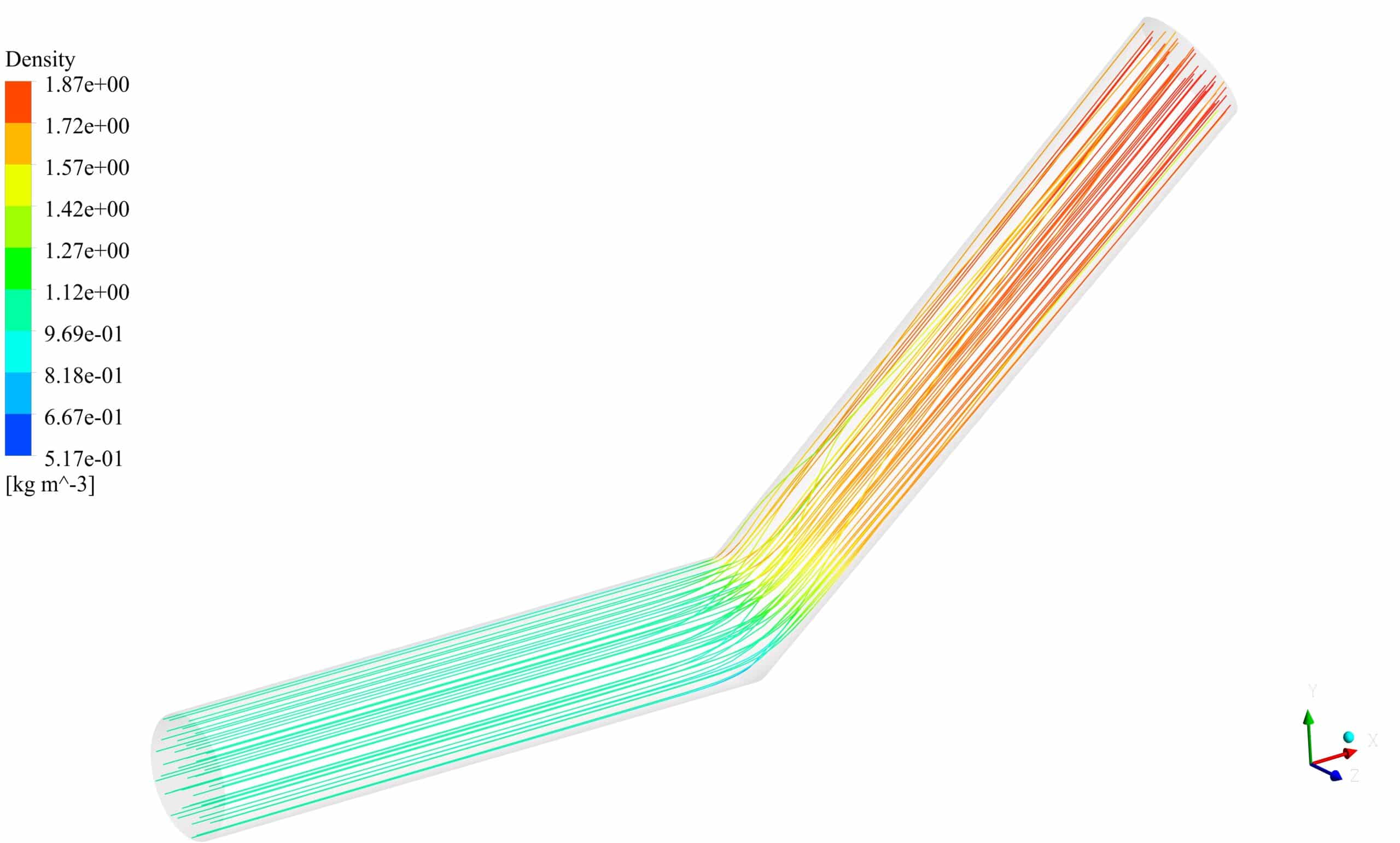
Air enters from the pipe inlet with 0.9 Mach number and 5 Celcius temperature. The fluid experiences an extreme pressure drop at the bending zone. The mentioned phenomenon is known as a shock wave and requires a high-quality mesh grid to be simulated.
The K-Omega SST viscous model was used to capture fluid behavior perfectly especially near the walls. On the other hand, the y-plus value is recommended to be under one value, but we`ve used a tetrahedron coarse mesh grid that couldn`t satisfy our criterion. As a result, a gradient adaption option was used to refine the mesh in zones with a high y-plus number.
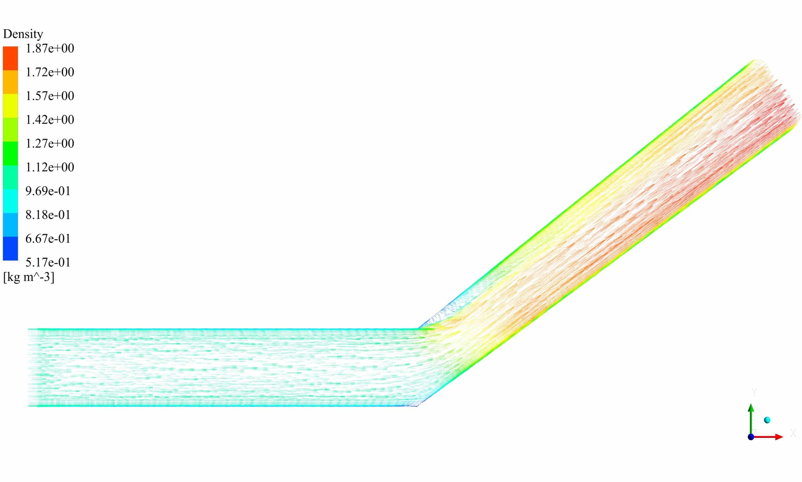
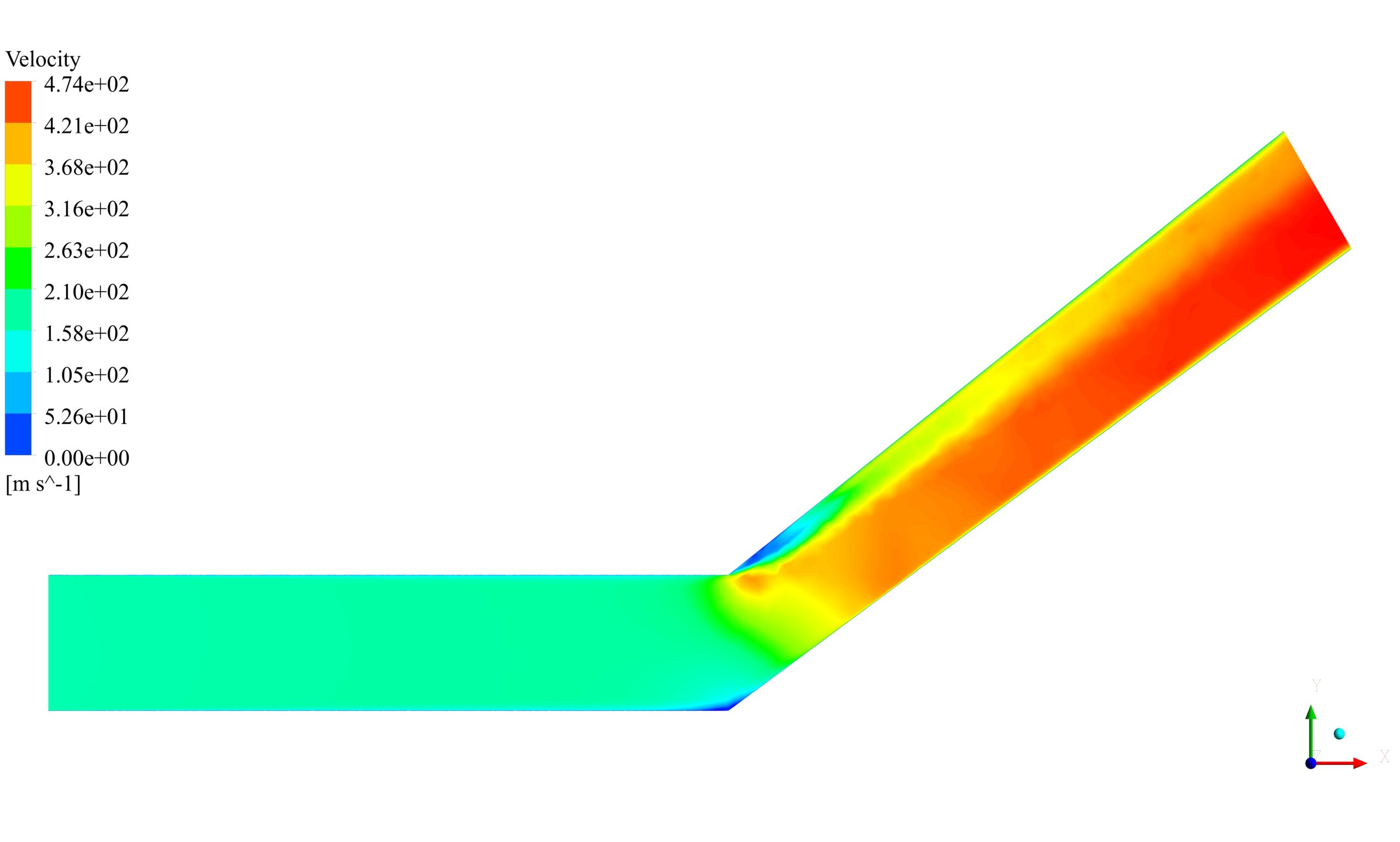
As shown in contours, pressure drops about 120kpa during the path and causes extreme variable distribution through the pipe.




Reviews
There are no reviews yet.