Counterflow CFD Simulation within a Canal, ANSYS Fluent Tutorial
$80.00 $40.00 Student Discount
- The problem numerically simulates a counterflow within a canal using ANSYS Fluent software.
- We design the 3-D model by the Design Modeler software.
- We Mesh the model by ANSYS Meshing software, and the element number equals 256899.
- We perform this simulation as unsteady (Transient).
- We use the VOF Multi-Phase model to define two phases: water and air.
To Order Your Project or benefit from a CFD consultation, contact our experts via email (info@mr-cfd.com), online support tab, or WhatsApp at +44 7443 197273.
There are some Free Products to check our service quality.
If you want the training video in another language instead of English, ask it via info@mr-cfd.com after you buy the product.
Description
Description
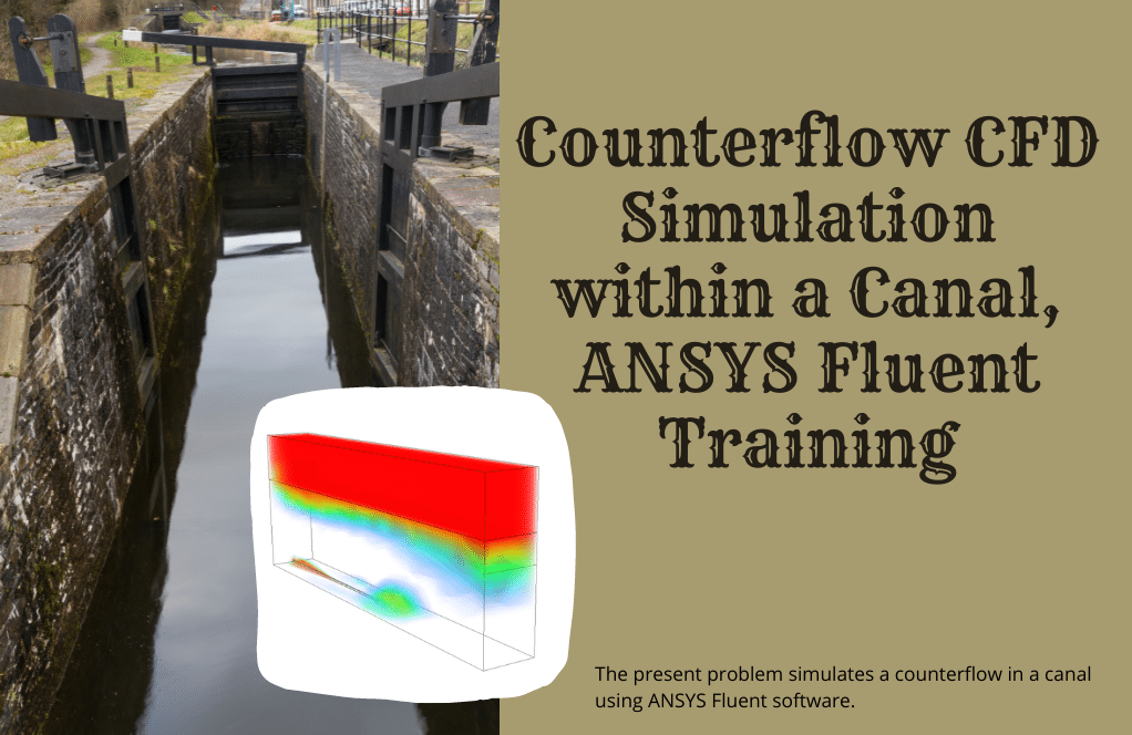
The present problem simulates a counterflow in a canal using ANSYS Fluent software. We perform this CFD project and investigate it by CFD analysis.
This work investigates fluid flow behavior when exposed to a flow in the opposite direction.
In this simulation, water flows from the canal into a rectangular section horizontally, and at the same time, another flow of water from a pipe lying on the floor of the same canal, horizontally but in the opposite direction of the initial flow into the canal.
The present model is designed in three dimensions using Design Modeler software.
The model’s geometry consists of a channel with a rectangular cross-section with a length of 8 m and a rectangular cross-section with a length and width of 3 m and 1 m. At the bottom of the canal, a 4 m long pipe and 0.05 m in diameter is lying down.
The meshing of the model has been done using ANSYS Meshing software. The element number is 256899.
Counterflow Methodology
The inlet water flow velocity from the rectangular section of the channel is defined as 0.3 m.s-1, and the inlet water flow velocity to the pipe is defined as 2 m/s.
Also, the spaces above this canal are considered special spaces for open-air flow, so the boundary condition of inlet pressure with relative pressure equal to zero is used.
Therefore, since the computational domain of the present model has two different types of fluids, including water and air, the multi-phase VOF model is used for the current simulation. Furthermore, the standard k-epsilon model is used to solve turbulent fluid equations.
Counterflow Conclusion
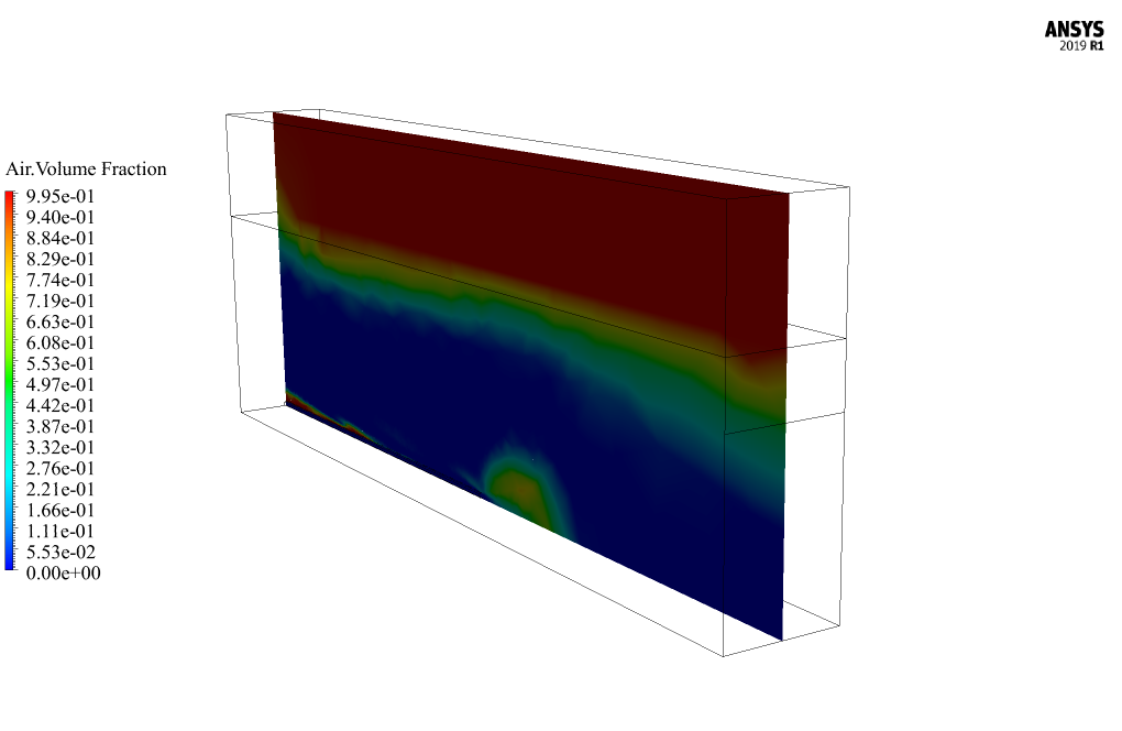
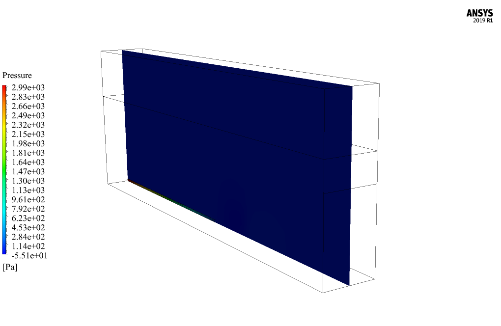
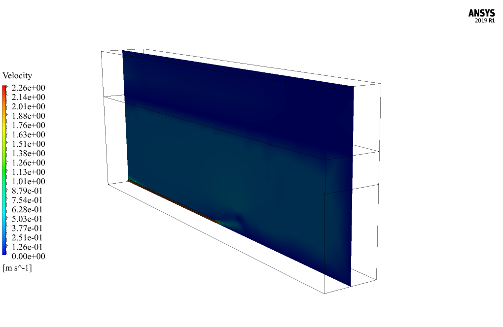
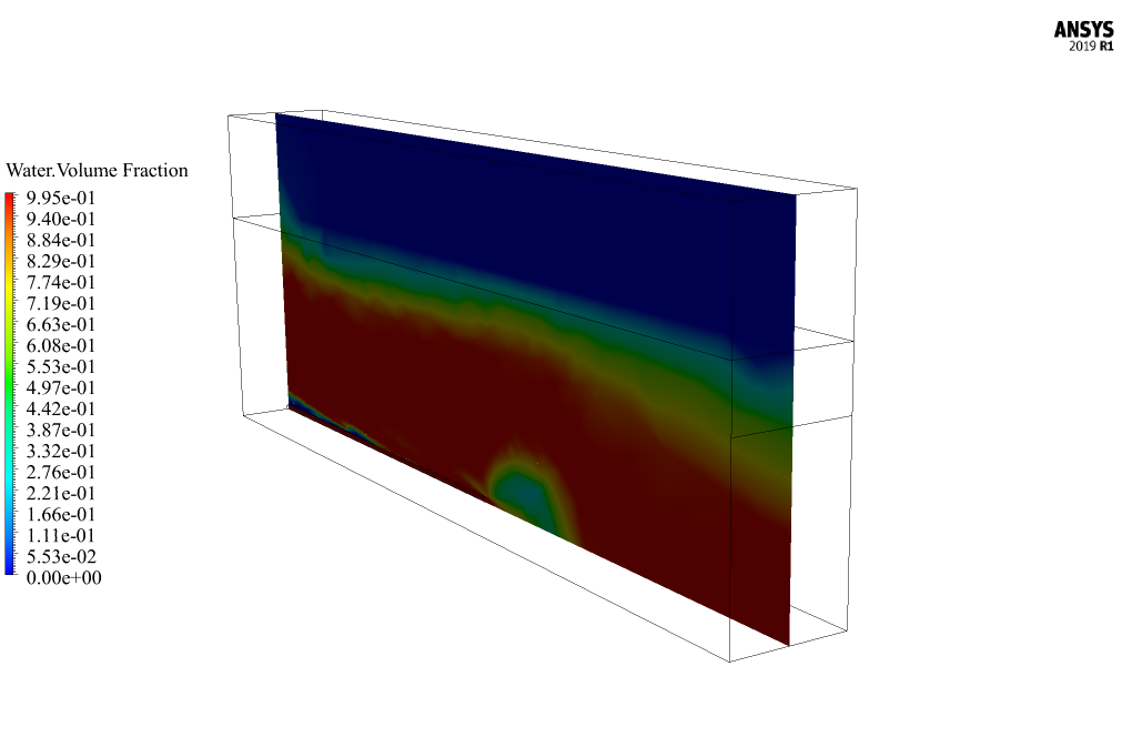
At the end of the solution process, two-dimensional and three-dimensional contours related to the pressure, velocity, and volume fraction of each of the air and water phases are obtained.
As seen in the air volume fraction contour, the injection of air in the opposite direction of water causes a locally reduced water volume fraction.


Omari Von –
I’m really impressed by the comprehensive approach to simulating counterflow in a canal. The detail provided on methodology and conclusions helps me understand the intricacies of fluid dynamics in such scenarios. Great work!
MR CFD Support –
Thank you so much for your positive feedback! We are thrilled to hear that you found the counterflow simulation details informative and helpful. Our team strives to provide thorough explanations to help our customers understand the complexities of CFD analysis. Your appreciation means a lot to us!
Myra Greenholt III –
This simulation seems complex with the counterflow. Did you have detailed instructions or tutorials to help understand how to set up this kind of simulation in ANSYS Fluent?
MR CFD Support –
We’re happy to hear that you’re interested! Yes, our product includes a comprehensive tutorial that guides you through each step of setting up and running a counterflow simulation in ANSYS Fluent. The tutorial is designed to be user-friendly for both beginners and experienced users, ensuring you can follow along and understand the process with ease.
Kennedy Heaney –
I’m amazed by how clear water and air interactions are depicted in the results. Can you take me through how different visualization techniques were used to distinguish between the phases?
MR CFD Support –
For the visualization of water and air phases in the simulation, the Volume of Fluid (VOF) multiphase model was used which clearly separates and tracks the interface between the phases. Contours of volume fraction illustrate the allocation of each phase, and sharp interface distinctions are achieved due to the methodology of the VOF model. 2D and 3D visualization techniques are employed to present distinct perspectives and depth of understanding regarding the distribution and influence of each phase in the canal during the counterflow simulation. In this way, the difference between air and water phases is made clear and can show where and how interactions take place, providing valuable insight into the flow behavior.
Mr. Samson Bruen Jr. –
I found the simulation fascinating, especially how the counterflow is visualized. Can you expand a bit on how the multi-phase VOF model was specifically utilized in this simulation?
MR CFD Support –
In the counterflow simulation, the Volume of Fluid (VOF) model was utilized to track the interface between the air and water phases present in the canal. This multi-phase model allowed accurate representation of the free surface and the mixing behavior as the two water flows interacted in opposing directions, providing realistic visualization and quantification of the complex flow dynamics at the intersection. The VOF model typically assigns a volume fraction to each cell within the grid, dictated by the presence and proportion of each fluid within that cell.
Ms. Caroline Parisian III –
I’m impressed with the detail included in this tutorial for setting up a counterflow simulation in a canal. The use of different fluid types and boundary conditions is well-explained. It helped me understand the dynamics of counterflow within such environments.
MR CFD Support –
Thank you for your kind words! We’re delighted to hear that the tutorial was helpful and provided you with a clear understanding of counterflow simulation dynamics. Your satisfaction is our top priority, and we appreciate you taking the time to share your positive experience. If you have further questions or need assistance with other projects, please feel free to reach out to us!
Anabel Murazik –
I just finished going through the Counterflow CFD Simulation tutorial, and I have to say it’s brilliantly detailed! Everything from setting up boundary conditions, meshing, and explaining the multiphase VOF model was covered diligently. It was especially helpful to see how the air injection impacts local water volume fractions. Great work!
MR CFD Support –
Thank you for your positive feedback! We’re thrilled to hear that you found the tutorial detailed and helpful. Your appreciation for the thorough explanation of the multiphase VOF model and boundary conditions means a lot to us. We strive to provide high-quality tutorials to assist our learners, and we’re glad to have met your expectations. If you ever have more questions or need further assistance, feel free to reach out!
Audreanne Hand –
I found the dual velocity input approach quite interesting. Could you elaborate on how the counterflow affects the overall flow dynamics within the canal?
MR CFD Support –
Certainly! In the counterflow simulation, introducing water at two different velocities from opposite directions causes disturbances in the flow pattern. This setup generates opposing momentum, leading to a complex interaction between the advancing and retreating water fronts. This interaction results in potential turbulence, mixing, and possible formation of vortices where the two flows meet. The overall flow dynamics are influenced by these factors, as well as the shape and dimensions of the canal, the characteristics of the flows’ entry points, and the computational simulation’s initial and boundary conditions.