Darrieus Turbine, Paper Validation by ANSYS Fluent
$330.00 $165.00 Student Discount
- The problem numerically simulates Darrieus vertical axis wind turbine using ANSYS Fluent software.
- We perform this simulation as unsteady (Transient).
- We perform the simulation according to a Reference Article and validate the power coefficient.
- We use the Sliding Mesh model to rotate the rotor of the wind turbine.
To Order Your Project or benefit from a CFD consultation, contact our experts via email (info@mr-cfd.com), online support tab, or WhatsApp at +44 7443 197273.
There are some Free Products to check our service quality.
If you want the training video in another language instead of English, ask it via info@mr-cfd.com after you buy the product.
Description
Project Description of Darrieus VAWT:
A vertical-axis wind turbine (VAWT) is a type of wind turbine where the main rotor shaft is set transverse to the wind and perpendicular to the ground. This arrangement provides VAWTs to capture wind energy in every azimuth angles. There are three types of VAWTs: Savonius which is a drag-based wind turbine, Darrieus wind turbine that works based on lift generation and H-type wind turbine.
The H-type wind turbine is actually like Darrieus but with different blades. In this project, we aim to validate a related paper entitled “ The Darrieus wind turbine: Proposal for a new performance prediction model based on CFD “.
According to the paper 2D simulation, the turbine has three NACA0021 blades and the diameter is 1010mm shown in figure below.
For better understanding, a three-dimensional view of the experimental setup is illustrated below. Note that, the geometry is designed in ANSYS Design Modeler software.
Moreover, ANSYS Meshing software is used to generate mesh grids. It should be considered that a coarse boundary layer or any size jump in cells will be caused errors. Therefore, the problem is highly grid-sensitive.
In the figures below, generated cells in the rotating domain, stationary zone and the vicinity of the blades are depicted. All in all, 904018 quad/tri cells were used.
Methodology of Darrieus turbine simulation:
The pressure-based solver type is used due to incompressibility of the air. Also, the simulation is performed in Transient mode. Most importantly, mesh motion (sliding mesh) is hired to rotate the rotor to investigate wind turbine performance.
Results:(Darrieus turbine numerical validation)
The wind turbine needs to rotate several rounds to get to its steady condition. Normally, it happens in the fifth or sixth round. Therefore, we need to monitor a crucial value like the moment coefficient of the wind turbine. As the difference in two consecutive rounds becomes less than 2%, we can be assured of the convergence.
The power coefficient of the wind turbine is achieved by multiplying TSR by the moment coefficient. The Tip Speed Ratio is defined as: (R: turbine radius, w: rotational velocity, V: uniform wind speed)
TSR= (w*R)/Vin
Note that, the moment coefficient can be reported by ANSYS Fluent. So with a simple calculation, the power coefficient is accessible. Thus, the power coefficient in 4 TSRs is calculated including 2, 2.5, 2.68 & 2.8 and then compared with the article.
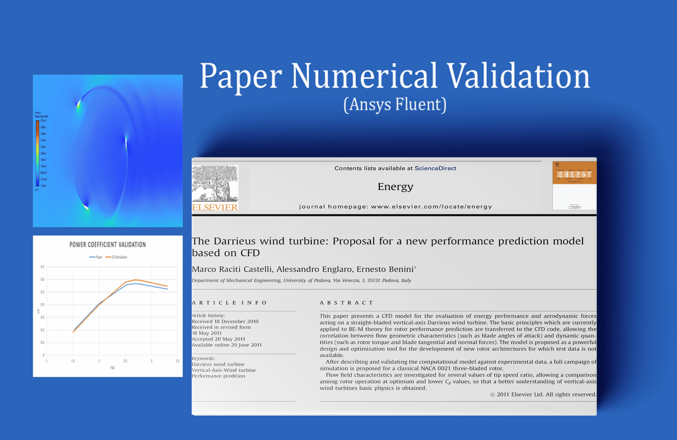
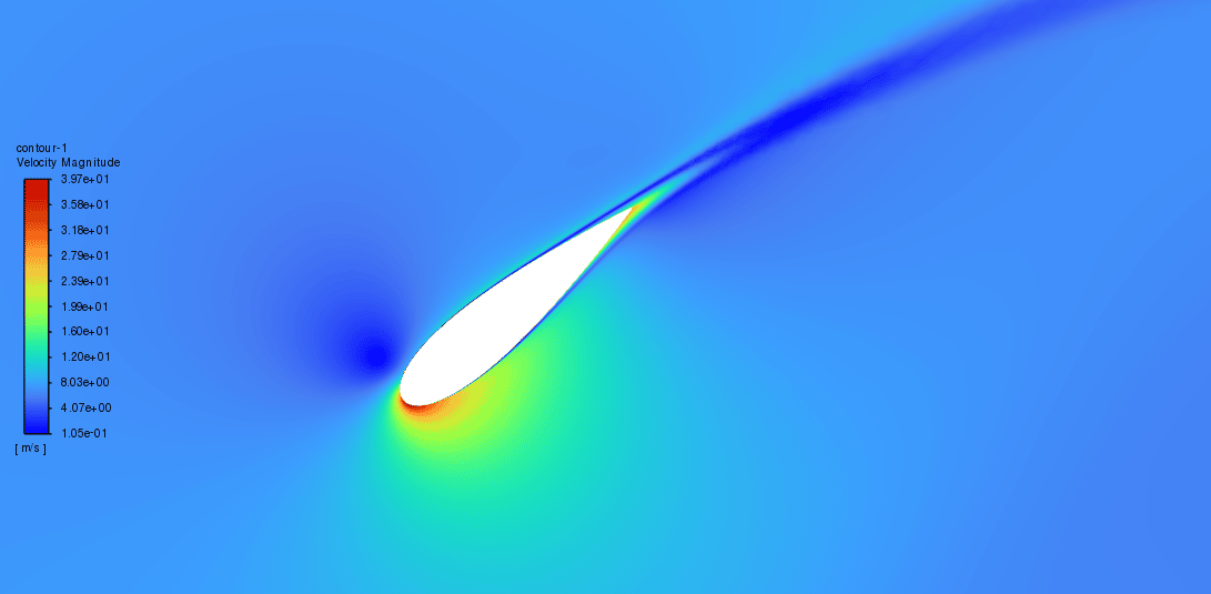
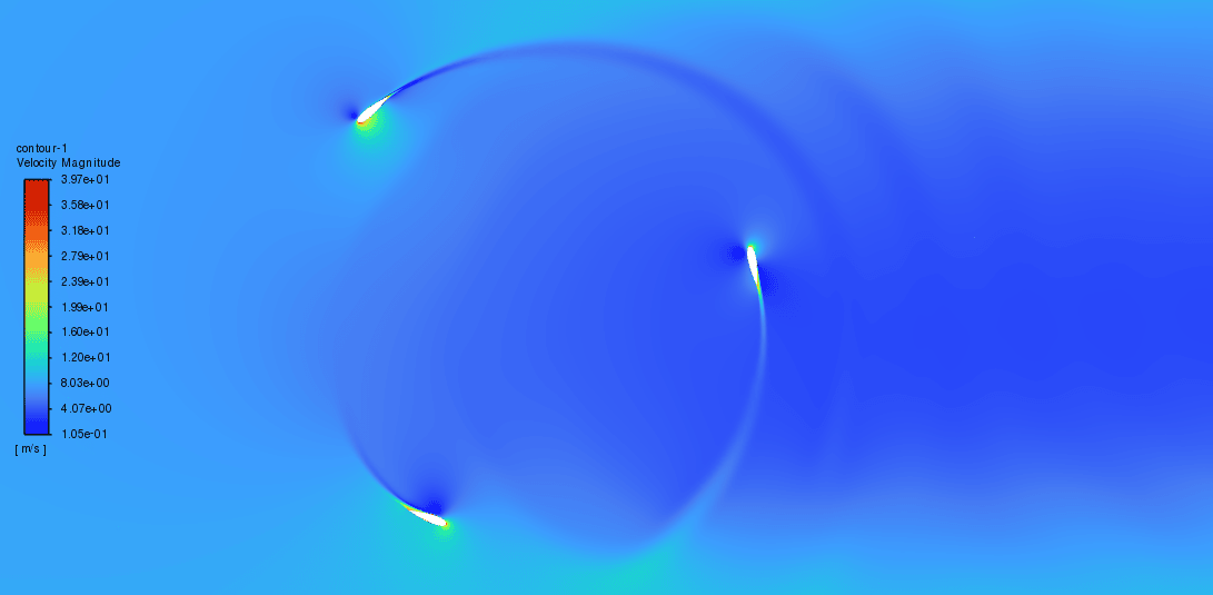
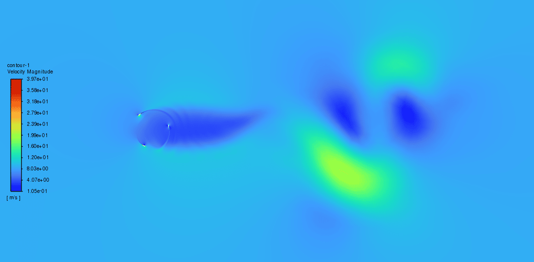
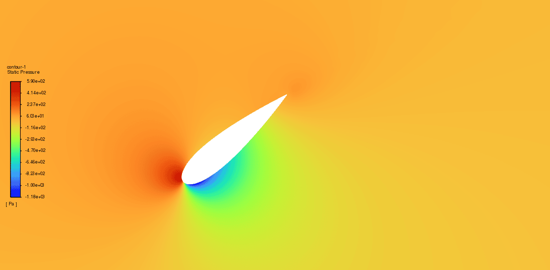
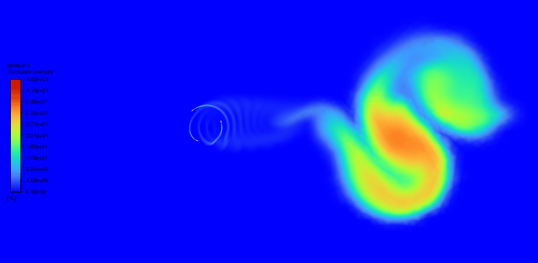
The figure below indicates the article and simulation data in a plot. The plot proves that the simulation results have a good agreement with the paper results. Finally, 2d contours of the velocity field, pressure distribution and turbulence intensity are exported.




Miss Lyda Hodkiewicz –
The review is excellent and showcases a strong understanding of the Darrieus Turbine CFD simulation process and results. Great job in highlighting the attention to detail in meshing and the methodology utilized to obtain the steady state of the turbine performance. Thank you for sharing the insight into how the power coefficient is calculated and validated against published data, providing credibility to the simulation results.
MR CFD Support –
Thank you so much for your detailed review! We’re delighted that our simulation and methodology conveyed a clear understanding, and you found the validation process thorough. Seeing the positive feedback on our attention to detail and the match between our results and the reference paper is very encouraging. We appreciate that you took the time to commend our work, and we look forward to providing high-quality simulations in the future.
Hadley Ritchie –
The project was incredibly fascinating and the simulation results are presented in a detailed and accessible manner. It’s really impressive how the contours were able to illustrate the turbine’s performance efficiently. Great job on this study!
MR CFD Support –
Thank you for your feedback! We’re delighted to hear that you’re pleased with the details and clarity of the simulation results. Our goal is to make complex simulations understandable and useful. If you have any further inquiries or need additional information, please don’t hesitate to ask.
Prof. Clair Konopelski –
I am very impressed with the results matching the paper data. I do wonder, how does the sliding mesh in the simulation account for the continuous rotation of the Darrieus turbine without causing numerical instability over time? Can anyone explain this aspect?
MR CFD Support –
To avoid numerical instability during continuous rotation, the sliding mesh uses a dynamic layering approach that continually adjusts the mesh topology. This ensures that as the turbine blades rotate, there’s minimal skewing of the cells, which helps maintain numerical stability throughout the simulation’s duration.
Lillian Goyette IV –
The project overview of the Darrieus Turbine is detailed and informative. It’s evident that care has been taken to ensure a high-quality mesh and accurately capture the physics of the turbine operation.
MR CFD Support –
Thank you for your positive feedback on our Darrieus Turbine CFD simulation project. We take pride in providing detailed and accurate simulations and are glad our commitment to quality is evident in our project descriptions and outcomes. If you have any more questions or need further information, feel free to reach out.
Samson Cronin DDS –
What aspects of the project validation were most accurately captured compared to the paper results? Were there any aspects that did not align as closely?
MR CFD Support –
In the project validation for the Darrieus Turbine simulation, the power coefficient at different Tip Speed Ratios (TSRs) was the aspect most accurately captured and compared to the results mentioned in the paper, showing good agreement. The simulation managed to reproduce the trends in power coefficient against TSR effectively. If there were any discrepancies, they were not detailed in the project description provided. However, minor deviations from paper results in CFD validations can occur due to factors like mesh quality, chosen turbulence model, or numerical settings, which wasn’t clearly mentioned in the context you’ve provided.
Korey Hartmann –
The validation process sounds impressive! Was evaluating the convergence based only on the difference in moment coefficient in consecutive rounds the sole criteria for assuring simulation accuracy?
MR CFD Support –
We’re glad to hear that you find our validation approach impressive! While monitoring the moment coefficient is crucial for establishing stable operation of the turbine, assuring the accuracy of the simulation includes other factors as well. These typically involve checking the overall balance of forces, scrutinizing residuals for all equations and watching for consistent patterns in any monitored physical quantities over time. Also, it’s standard to compare simulation data with experimental results, as we did using the article’s data in the plot.
Mrs. Dorris Langosh –
The explanation on the methodology is thorough, but I’m curious if there’s any clarification on how turbulence is modelled in this study?
MR CFD Support –
Turbulence in this study is typically modeled using appropriate turbulence models available in ANSYS Fluent, such as the k-epsilon or k-omega model, to capture the complex flow behavior around the rotating blades of the Darrieus turbine. The choice of the model depends on the requirements laid out in the original paper that’s being validated.
Miss Jakayla Lang –
Great course to understand dynamical simulation of wind turbines! However, what was the reason behind using a Tri-quad mesh arrangement?
MR CFD Support –
We utilized a combination of quad and tri elements in the mesh to capture the complex geometry of the blades accurately while balancing computational efficiency. Areas closer to the blades require higher fidelity to accurately capture the boundary layer effects, hence the finer quad cells there. In contrast, tri cells are used in regions further away from critical flow features to reduce computational cost without significantly compromising solution accuracy.
Delpha Wiza DVM –
I’m impressed with how you validate the Darrieus wind turbine performance based on a scientific paper. Could you tell me what specific factors were varied to assess the turbine’s performance in the simulation and in the paper?
MR CFD Support –
In the validation of the Darrieus wind turbine, specifically the Tip Speed Ratio (TSR) was varied in the simulation as well as in the paper to assess the turbine’s performance. This is a crucial factor as it relates to the rotational velocity of the turbine relative to the wind speed and directly affects the power coefficient. By comparing the power coefficient at different TSR values obtained from the simulation with those reported in the paper, the performance of the turbine and the accuracy of the simulation are assessed.
Prince Langworth I –
I’m really interested in the validation process for the Darrieus wind turbine. Can you elaborate on how the validation against the paper’s model ensured that the simulation produced accurate results?
MR CFD Support –
The validation process involved running simulations at various Tip Speed Ratios (TSRs) and then calculating the power coefficient from the moment coefficient which was reported by ANSYS Fluent. By ensuring that the difference in the moment coefficient between consecutive rounds was less than 2%, it was possible to establish confidence in convergence. The power coefficient values obtained at different TSRs were then directly compared with those outlined in the paper. If these values were in close agreement, as indicated by the plot comparison, it meant that the computational model was accurately mimicking the paper’s physical model and hence deemed successful in terms of validation.
Antonette Kilback –
I was impressed with the validation process for the Darrieus turbine simulation. Can you explain how the sliding mesh technique is utilized in the simulation to replicate the turbine’s rotation in the wind?
MR CFD Support –
The sliding mesh technique is employed to simulate the rotating motion of the wind turbine blades within the airflow. It basically allows the mesh in the rotor domain to rotate while the rest of the computational domain remains stationary. This simulates the turbine’s operation and provides insight into the turbine’s aerodynamic performance under varying wind conditions.
Evie Kessler –
Fantastic product! The Darrieus Turbine validation simulation really showcased the in-depth capabilities of ANSYS Fluent. Your detailed grid sensitivity and the transient sliding mesh approach illuminate important aspects of CFD turbine simulation. The success in matching the power coefficients with the published paper is very impressive and instills confidence in the predictive power of simulations carried out with your guides.
MR CFD Support –
Thank you for your positive feedback! We’re glad to hear that our Darrieus Turbine validation simulation met your expectations and that you found our approach to predicting performance to be thorough and reliable. If you have further questions or need more detailed insights, don’t hesitate to reach out.