Combustion Chamber Performance Optimization, DOE
$270.00 $135.00 Student Discount
In this project, combustion chamber performance is optimized using DOE and RSM.
Click on Add To Cart and obtain the Geometry file, Mesh file, and a Comprehensive ANSYS Fluent Training Video.To Order Your Project or benefit from a CFD consultation, contact our experts via email (info@mr-cfd.com), online support tab, or WhatsApp at +44 7443 197273.
There are some Free Products to check our service quality.
If you want the training video in another language instead of English, ask it via info@mr-cfd.com after you buy the product.
Description
Combustion Chamber Performance Optimization, Design of the Experiment (DOE)
What is the Design of the Experiment (DOE)?
Design of Experiments (DOE), also referred to as Designed Experiments or Experimental Design – is defined as the systematic procedure carried out under controlled conditions to discover an unknown effect, to test or establish a hypothesis, or to illustrate a known effect. It involves determining the relationship between input factors affecting a process and the output of that process. It helps to manage process inputs to optimize the output.
Sir Ronald A. Fisher first introduced the method in the 1920s and 1930s. Design of Experiment is a powerful data collection and analysis tool used in various experimental situations. It allows manipulation of multiple input factors and determination of their effect on the desired output (response). By changing multiple inputs simultaneously, DOE helps to identify significant interactions that may be missed when experimenting with only one factor at a time. We can investigate all possible combinations (full factorial) or only a portion of the possible combinations (fractional factorial).
A well-planned and executed experiment may provide a great deal of information about the effect on a response variable due to one or more factors. Many experiments involve holding certain factors constant and altering the levels of another variable. However, this “one factor at a time” (OFAT) approach to processing knowledge is inefficient compared to changing multiple factor levels simultaneously.
As was mentioned previously, there are multiple approaches to DOE. OFAT, Full and Fractional factorial, Taguchi, and Response surface methodology (RSM). However, the RSM proves to be the best approach among the existing methods for DOE.
What is Response Surface Methodology (RSM)?
Response Surface methodology, or RSM for short, is a set of mathematical methods determining the relationship between one or more response variables and several independent (studied) variables. This method was introduced by Box and Wilson in 1951 and is still used today as an experimental design tool. RSM is a set of statistical techniques and applied mathematics for building experimental models. The goal in RSM is to optimize the response (output variable) affected by several independent variables (input variables). An experiment is a series of tests called executions. In each experiment, changes are made to the input variables to determine the causes of the response variable’s changes. In response-level designs, constructing response procedure models is an iterative process.
As soon as an approximate model is obtained, it is tested by the good-fit method to see if the answer is satisfactory. If the answer is not confirmed, the estimation process starts again, and more experiments are performed. In designing experiments, the goal is to identify and analyze the variables affecting the outputs with the least number of experiments. This method achieves the best response surface by discovering each design variable’s optimal response level. In designing experiments, the goal is to identify and analyze the variables affecting the outputs with the least number of experiments.
What is Optimization in ANSYS Fluent?
Optimization is the process of acquiring the best answer for a selected parameter. Using ANSYS, one can perform two types of Optimization. 1-Direct Optimization, 2-Indirect Optimization. Both of these methods will result in the same answer but with different steps. Direct Optimization predicts the behavior of a system without any intermediary step. In contrast, indirect Optimization needs the data obtained by the RSM to provide the user with the correct mathematical function for predicting the system behavior.
What do I learn from this tutorial?
Step 1
In the first part of this tutorial that experienced Engineers in the MR-CFD company prepared you will first learn about different DOE methods, including RSM and its history. Next, the advantages or disadvantages of these methods over one another will be explained along with their theoretical aspects. Therefore, you can be sure you will learn the theoretical bases you need in the introductory section even if you don’t have any experience in the field of DOE or Optimization whatsoever.
Step 2
In the second part, the RSM optimization process is conducted using ANSYS software. This project will show you how to apply this method to optimize different combustion chamber parameters step by step. For instance, we will start from scratch by designing the geometry of the combustion chamber and show you how you can parametrize your design. In the next step, you will see how the meshing is performed over the designed geometry. Next, we will explain how to set up Fluent software and define other needed parameters. After that, we will show you how to perform a parameter correlation process to find out which input parameters have a significant effect on our output parameters to reduce the number of input parameters and hence our computational time by omitting the less needed input parameters.
Finally, using the Central Composite Method (CCD), which is a subset to RSM, we generate the design point chart, which includes all the needed experiments to perform the Optimization by defining the investigation span for each parameter. In simple words, indirect Optimization in ANSYS uses the generated data by RSM to extract a mathematical function that can predict the system’s behavior.
Step 3
In the next part, the direct optimization process is explained in detail. In this type of Optimization, in contrast to the previous method (RSM), the design points will be created based on the need of the software and based on a predefined algorithm. As the optimization process advances, the software may decide it needs more sampling points to predict the mathematical function of the system accurately. In other words, opposite to Optimization using RSM, the whole Optimization is performed directly without any intermediary step. Finally, when the process is finished, ANSYS will provide you with 3 candidate points that are the best answers for your system based on the user-defined objective(s) (i.e., the circumstances you want your model to meet)
Project description
In this project, the combustion process inside a combustion chamber is simulated, and parameters such as heat generation rate, pollution formation, etc., are monitored. (The list of input and output parameters is shown in the following table.) As was mentioned in the previous paragraphs, the target of this project is to optimize the geometrical parameters of the combustion chamber for targets such as maximizing the value of heat generation rate while minimizing the amount of formed pollution. Two types of optimization are examined in this project; Indirect optimization using the RSM method and direct optimization. In the indirect optimization step, we use the CCD method to generate the design points needed to perform the RSM analysis. Then we will perform a parameter correlation process to identify the most effective input parameters on our model.
Next, we will show you how to optimize the combustion chamber’s input parameters based on the data which was generated for RSM analysis.
Direct Optimization
In the second part, we show the steps to performing direct optimization in which we will first generate the design points needed for the optimization process and then by defining desired target(s) (such as maximizing the value of heat generation rate while minimizing the amount of formed pollution), the software will start the optimization process and will provide you with the best three candidate points.
The RNG k-epsilon model is exploited to solve turbulent fluid equations. The energy equation is enabled to calculate the temperature change and model the heat transfer. Also, the species transport model along with the volumetric reaction option, has been activated to simulate the combustion process inside the cylindrical combustion chamber.
| Input parameters | The span of variations for input parameters | Output parameters |
| Cone angular velocity | 100-400 rad/s | Outlet temperature |
| Outer diameter | 0.099-0.121 m | CO2 mass fraction |
| Cone height | 0.027-0.033 m | CO mass fraction |
| Cone length | 0.27-0.33 m | Average temperature |
| Air inlet diameter | 0.0018-0.0022 m | Total heat generation |
| Fuel inlet diameter | 0.009-0.011 m | Chamber heat flux |
| Air inlet offset | 0.009-0.011 m | |
| Fuel inlet offset | 0.009-0.011 m | (DOE) |
Geometry and Mesh
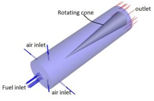
We design the geometry of the present project in ANSYS Design Modeler software. It consists of several parts, like 4 Fuel inlets on the bottom face of the combustion chamber, and 4 air inlets offset to produce a swirl flow inside the combustion chamber, and a rotating cone inside the chamber to increase the effect swirl over the combustion efficiency.
Also, We carry out the meshing of the model in ANSYS Meshing software and apply a specific body sizing over each generated geometry based on the geometrical input parameters.
CFD simulation settings
- Simulation applies a pressure-based solver.
- The present simulation and its results are steady and do not change as a function of time.
- We ignore the effect of gravity.
The following table summarizes the applied settings.
| Models | ||
| Viscous model | k-epsilon | |
| k-epsilon model | RNG | |
| near-wall treatment | standard wall function | |
| Species | Species transport | |
| Reaction | Volumetric | |
| Turbulence chemistry interaction | Eddy-dissipation | |
| Energy | On | |
| Boundary conditions | ||
| Inlets | Mass flow inlet | |
| Air | Mass flow rate | 0.00036135 kg/s |
| Temperature | 300 K | |
| Fuel | Mass flow rate | 3 kg/s |
| Temperature | 300 K | |
| Outlet | Pressure outlet | |
| Walls | ||
| Chamber wall & wall-solid | Wall motion | Stationary wall |
| Thermal | Convection | |
| h = 25 W/m2K | ||
| Free stream temp = 300K | ||
| Cone | Wall motion | Rotating wall |
| Rotating velocity | CA (input parameter) | |
| Thermal | Heat flux = 0 W/m2 | |
| Solution Methods | ||
| Pressure-velocity coupling | Coupled | |
| Spatial discretization | pressure | second-order |
| momentum | second-order upwind | |
| Mass fraction of species | second-order upwind | |
| turbulent kinetic energy | second-order upwind | |
| turbulent dissipation rate | second-order upwind | |
| Energy | second-order upwind | |
Result and discussion
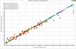
As can be seen in the goodness of fit graph, there is a good agreement between the predicted values (predicted function) and the points that have been simulated. Therefore, the obtained data can be trusted to give you the optimal values for each outlet parameter based on the inputs. You can extract many different 3D surfaces to view the results better and understand the mutual effects of each input parameter over the output.
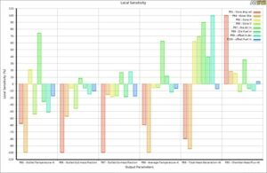
By viewing the local sensitivity chart, you can understand which input parameter significantly affects outputs. For instance, in this project, you can easily say that the combustion chamber’s cone angular velocity and outer diameter play a distinct role almost over all the output parameters.
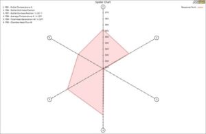
Finally, in the spider chart, you can observe the responses for each parameter. (i.e., when we have the highest value for parameters 1,2,4,5 and 6, parameter 3 will have its least value, which is entirely logical since when we have a complete stoichiometric reaction, the generated heat will reach its highest value while the mass fraction of CO will reach zero.)




Emmy Buckridge IV –
The tutorial was highly informative and equipped me with all the crucial knowledge for optimizing a combustion chamber. I appreciate the balance between theoretical explanation and practical application. The DOE being broken down into vivid steps made the complex ideas much easier to grasp. The simulation settings and detailed result discussion offered me great insights into the process. Excellent resource for anyone looking to master DOE and optimization in ANSYS.
MR CFD Support –
Thank you so much for your kind words and thoughtful review. We’re thrilled to hear that you found the tutorial on Design of Experiments and optimization in ANSYS Fluent both informative and practical. It’s always our aim to create educational content that balances theory and application, so we’re glad to see that it resonated with you. We look forward to providing you with more learning materials in the future!
Dr. Sonia Denesik II –
I’m currently learning about combustion chamber design and I found this elucidation very insightful. But I was wondering, could you clarify how the RNG k-epsilon model differs from the standard k-epsilon model in simulating turbulent fluid flow in this context?
MR CFD Support –
The RNG k-epsilon model is an advanced version of the standard k-epsilon model. It takes into account the effects of swirls and rapid strain in turbulent flows, which enhances the accuracy for flows that involve significant curvature, recirculation or swirl, and separating flows. It’s particularly useful in simulating the turbulent flow within combustion chambers like in this project, as it can provide better prediction of the flow field’s effects on the combustion process.
sajad nasiri –
Very practical, thanks MR CFD.
asha –
thanks, Mr CFD for publishing this training video. I have used this package in my Ph.D. thesis, the number of my simulation experiment has been reduced so much, and the result was so most perfect for presentation in my research paper. do you have any service in this area also?
how can I connect with you?
Reza Amini –
thanks, dear Asha,
you can call us on WhatsApp or email us
info@mr-cfd.com
+19032313943
christian –
the perfect training package, I have read this package and I have some questions, how can I be in touch with your expert in this area?
best regards
Christian
Reza Amini –
thanks, dear Christian for your purchase
you can be in touch with us via mail and WhatsApp
info@mr-cfd.com
+19032313943
pasha –
hello dear MR CFD
what is the advantage of this type of investigation compared to the classic investigation? do you have any sample of the published paper of your own ?
Reza Amini –
hello dear pasha
as it has been explained in this post, the number of experiments by this way will be reduced and you can investigate the effect of the various parameters in so lower time and also you can predict the effect of parameter interaction on your output parameters like predicting the effect of shell and tube diameter and also the various Reynolds and nanofluid concentration on pressure drop and heat transfer coefficient in a shell and tube heat exchanger.
anisha hamza –
also this our published article in this area
https://www.sciencedirect.com/science/article/abs/pii/S2451904920303322
you can take a look at the result that you can extract from the design of experiment and response surface method by using Ansys fluent and Ansys workbench softwares
Jevon Bergnaum –
I’m very impressed with how comprehensive the DOE tutorial is! It seems like every step of the optimization process is thoroughly explained. However, does the tutorial include any practical examples to help users apply these techniques in different scenarios?
MR CFD Support –
Thank you for your kind words about our DOE tutorial. Indeed, the tutorial offers practical guidance on applying optimization techniques to a combustion chamber model, providing detailed steps and insight into using the DOE methodologies. We strive to include both theoretical background and hands-on examples so that users can confidently apply these techniques to a variety of scenarios beyond the tutorial’s scope.
Noemi Upton DDS –
I was really impressed with the thorough explanation of DOE provided in this tutorial. It simplifies complex scientific processes and provides a step by step guide that ensures beginners and experts alike could follow along. By introducing the history, explaining the theoretical concepts, and demonstrating the practical application using ANSYS software, this resource conveys the material in a very educational yet digestible way.
MR CFD Support –
Thank you so much for your kind words, we are delighted to hear that you found the tutorial on Design of Experiments and Optimization in ANSYS Fluent so enlightening and easy to follow. Our aim is always to present complex concepts in an approachable and comprehensive manner, so we’re glad it resonated with you. We appreciate your feedback!
Clint Jerde –
The presentation on optimizations in ANSYS Fluent was insightful! The steps outlined for applying RSM in design and the comparative overview of direct versus indirect optimization methods are particularly beneficial. Having both theory and application within one course offers a solid learning curve for engineers keen on deep-diving into DOE for combustion chambers.
MR CFD Support –
Thank you for your positive feedback! We’re thrilled to hear that the tutorial on Combustion Chamber Performance Optimization and the inclusion of both theoretical and practical aspects of DOE as well as different optimization methods in ANSYS Fluent has contributed to your understanding and learning experience. We strive to provide comprehensive and applicable knowledge for engineers and it’s heartening to know that you found it beneficial!
Vallie Lynch –
The tutorial sounds in-depth, but I’m confused about one point – does performing a parameter correlation process eliminate less significant parameters, or are they simply downplayed in the optimization?
MR CFD Support –
The correlation process in a DOE identifies which input parameters have the most significant effect on the output parameters. This information is then used to either eliminate the less significant parameters from further consideration or limit their impact on the final optimization. Usually, parameters found to have minimal influence on the output may not be varied in the later stages of the optimization process, allowing the focus to shift to inputs that have more significant effects on the performance indicators being studied.
Zita Bruen –
I’ve just gone through the tutorial and found it incredibly detailed. The steps for conducting DOE and optimization in ANSYS Fluent are thoroughly explained and easy to follow. Thanks to this guided project, I feel well-versed in applying RSM for process optimization specifically within the context of combustion chamber performance.
MR CFD Support –
We are delighted to hear that you found the tutorial for Combustion Chamber Performance Optimization using DOE not just engaging, but also instructive and valuable. Your feedback is appreciated and motivates us to continue delivering high-quality educational content. Thank you for choosing our tutorial and for taking the time to submit such a positive review.
Dr. Paxton Cronin –
I really appreciated the comprehensive tutorial on the DOE, RSM, and combustion chamber optimization techniques. I’ve learned so much about how the input parameters affect the output and how to optimize for the best performance. The direct and indirect optimization techniques were clearly explained, and I feel I can apply these methods confidently in my projects now.
MR CFD Support –
Thank you for your feedback! We’re pleased to hear that our tutorial was informative and valuable to your learning experience. We strive to provide clear and practical information that can be readily applied to real-world scenarios. Should you need any further assistance, don’t hesitate to reach out!
Dr. Durward Powlowski Jr. –
Can you explain how the optimization process takes into account the various combustion chamber design parameters like cone height, air inlet diameter, etc.?
MR CFD Support –
In the optimization process, key geometrical parameters such as cone height, air inlet diameter, and others are treated as input variables. The software systematically modifies these parameters within a predefined range to perform simulations and evaluate the effects on output parameters like temperature, pollutant formation, etc. This is done to find the optimal combination of design variables that achieve desired performance objectives, such as maximum heat generation and minimum pollution.
Natasha Mayer II –
I really appreciate the depth of knowledge provided in this tutorial—particularly how DOE and RSM are leveraged for optimization within ANSYS Fluent. Not only does it detail the processes of Indirect and Direct Optimization, but the manner in which it outlines the practical combustion chamber optimization is admirable.
MR CFD Support –
Thank you very much for your kind words! We’re thrilled to hear that you found the tutorial on Combustion Chamber Performance Optimization informative and helpful. It’s always our goal to provide comprehensive and detailed guides that empower our users to achieve their simulation goals more efficiently. Your feedback is greatly appreciated!
Hollis Douglas –
Thank you for the incredibly detailed and effective tutorial on chamber performance optimization. The balance between theoretical explanation and hands-on ANSYS Fluent work was just right. It made grasping the concepts of DOE and RSM much more understandable and will without a doubt enhance my future projects. The project description gave a clear roadmap from the geometry design to the simulation settings and the final results in ANSYS. Such a comprehensive guide is a rare find, and the expertise of MR-CFD engineers is evident throughout the tutorial.
MR CFD Support –
We are thrilled to hear that you found our tutorial on Combustion Chamber Performance Optimization using DOE and ANSYS Fluent to be of great use. It’s delightful that our efforts to balance theory with practical application have aided you in better understanding these complex concepts. Thank you for your kind words and for recognizing the skill of our engineers. We take pride in providing valuable insights and guidance to our customers to support their success, and it’s fantastic to know we’ve made a positive impact on your projects. If there’s anything more we can assist you with, please don’t hesitate to ask!
Miss Aglae Block –
The practical application of how DOE integrates with ANSYS Fluent is fascinating. Could you clarify how the RNG k-epsilon model specifically benefits this type of simulation?
MR CFD Support –
Certainly! The RNG k-epsilon model enhances the accuracy of simulations involving turbulent flows, as it addresses the scale and influence of different turbulence eddy sizes. In the combustion chamber simulation, this model helps by providing better predictions of the turbulent mixing and recirculation, fundamentally important for optimizing the combustion efficiency and reducing pollutant formation.
Francesco Jerde –
I was particularly impressed by how DOE and RSM are applied in optimizing the combustion chamber’s performance, but I’m curious, how does the use of a rotating cone inside the chamber enhance combustion efficiency?
MR CFD Support –
Thank you for your compliment and inquiry regarding the combustion chamber’s design. The rotating cone inside the chamber imparts a swirl to the incoming airflow, which increases turbulence. This enhanced turbulence improves the mixing of the fuel with the air, resulting in a more thorough and uniform combustion process. Consequently, increasing combustion efficiency and creating a more stable flame, while potentially reducing the formation of pollutants.
Dr. Malcolm Erdman Sr. –
The explanation about using a rotating cone inside the combustion chamber to increase combustion efficiency was interesting! How exactly does the rotating cone improve the swirl effect and combustion efficiency?
MR CFD Support –
Thank you for your positive feedback about our product! The rotating cone inside the combustion chamber enhances the swirl effect by increasing the turbulence within the chamber. This augmented turbulence promotes better mixing of the fuel and the air, leading to a more homogenous mixture. A uniform mixture enhances the combustion process, enabling more complete burning of the fuel, thus increasing combustion efficiency. Enhanced efficiency results in higher heat generation rates and potentially lower emissions, as the fuel is burnt more thoroughly.
Ceasar Sawayn –
I’m super impressed with the depth of the tutorial on optimizing a combustion chamber! Just one thing: which part of the tutorial offers insights on interpreting the simulation results?
MR CFD Support –
Glad to hear you appreciate the detail of the tutorial! The interpretation of the simulation results is extensively covered in the ‘Result and discussion’ section. It provides insights into how well the predicted values align with the simulated points and effectively communicates the dependency of output parameters on various input variables.
Clyde Hansen –
This tutorial seems comprehensive but could you clarify the advantages of using a Response Surface Methodology (RSM) over other DOE methods?
MR CFD Support –
Response Surface Methodology (RSM) provides several advantages over other DOE methods. Notably, RSM can optimize multiple input variables efficiently by identifying the relationships between these inputs and the resulting outputs. Other advantages include the ability to model interactions between variables, reduce the number of experimental trials required, and generate a mathematical model of the system that can be used for further analysis and prediction of optimal conditions.
Rebekah Shields –
This tutorial on combustion chamber optimization using DOE in ANSYS is thorough and well-structured, offering a step-by-step approach for various levels of expertise. I appreciate the level of detail in the procedure, particularly the explanation on how to utilize Response Surface Methodology for optimal performance. It was also great to see how both indirect and direct optimizations were applied in practical scenarios.
MR CFD Support –
Thank you for your kind words! We are delighted to hear that our tutorial was comprehensive and helpful. We put a great deal of effort into ensuring that our tutorials are clear and accessible to all levels of users. Your feedback is very much appreciated and motivates us to continue providing quality learning materials. If you have any more questions or need further assistance in the future, don’t hesitate to ask!
Elliott Gibson DVM –
This tutorial looks incredibly detailed. Are the parameter correlations shown with actual CFD data or theoretical predictions?
MR CFD Support –
Parameter correlations in this tutorial are determined using CFD data obtained from the simulation of various design points. After conducting simulations for each design set by the DOE, these correlations between input and output parameters are analyzed to identify significant factors affecting the performance of the combustion chamber. The tutorial guides you through this process step by step to understand better how to optimize these parameters for the best results.
Avis Gislason –
This project description was comprehensive, however, I am curious about how the optimization done through ANSYS Fluent compares with real-world data. Is the simulation reliable enough to be used in actual combustion chamber design, or do we typically see significant discrepancies between the simulated and actual performance?
MR CFD Support –
Simulations done in ANSYS Fluent, like the one for combustion chamber performance optimization, are typically a good representation of real-world scenarios when set up correctly. The reliability of the simulations depends on the accuracy of the input data, the precision of the meshing, the chosen models, and the boundary conditions. In the industry, these simulations are often validated with experimental data. It’s common practice to start with simulation to narrow down design options and then perform real-world tests to fine-tune the designs. Discrepancies between simulated and actual performance are usually resolved with iterative testing and validation.