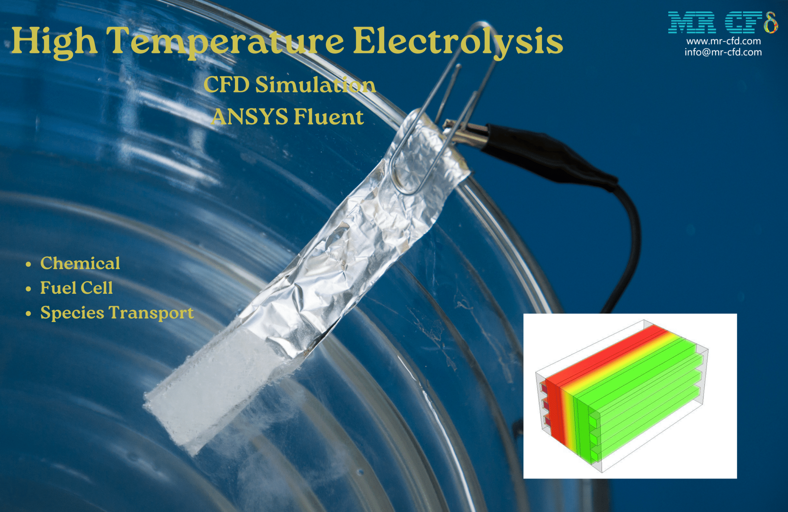
High-Temperature Electrolysis CFD Simulation, ANSYS Fluent
$300.00 $150.00 Student Discount
- The problem numerically simulates the Electrolysis using ANSYS Fluent software.
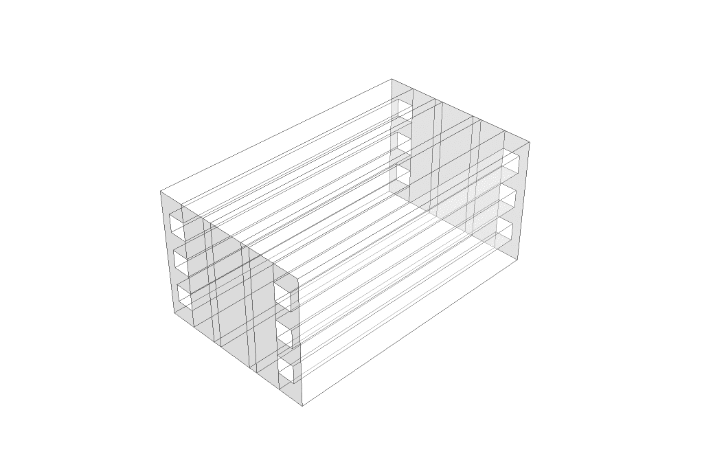
- We design the 3-D model with the Design Modeler software.
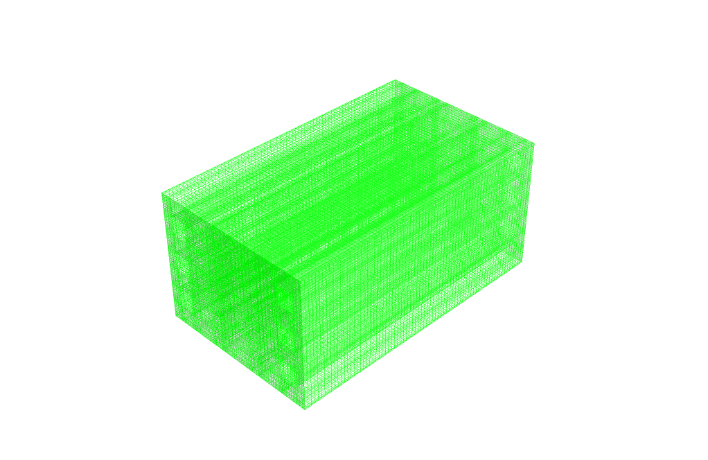
- We mesh the model with ANSYS Meshing software, and the element number equals 2,393,706.
- We use the Fuel Cell and Electrolysis Model and the Electrolysis sub-model.
- We used the Species model to define H2, O2, and H2O.
To Order Your Project or benefit from a CFD consultation, contact our experts via email (info@mr-cfd.com), online support tab, or WhatsApp at +44 7443 197273.
There are some Free Products to check our service quality.
If you want the training video in another language instead of English, ask it via info@mr-cfd.com after you buy the product.
Description
Description
In this project, we perform the numerical simulation of a High-Temperature Electrolysis using ANSYS Fluent software.
This product is the second chapter of the Electrolysis Training Course.
A fuel cell is an energy conversion device that converts the chemical energy of fuel into electrical energy. Electrolysis is the reverse of a fuel cell. That is, electricity is used to produce fuel (hydrogen) and water.
Electrolyzers, like fuel cells, have two electrical poles (electrodes) called the anode and cathode. These chemical reactions take place in these electrodes. In addition, fuel cells have an electrolyte and a catalyst. The electrolyte layer is used to transport charged particles (ions) between the electrodes, while the catalyst layer increases the speed of reactions in the electrode layers. The water vapor is fed to the electrolyzer, and electrons are also required for the reaction to take place.
High Temperature Electrolysis Methodology
We simulated this project based on the CFD method by ANSYS Fluent software. First, we designed the geometry of the model in 3D using Design Modeler software. The computational domain of the model is related to the interior space of a fuel cell. Then, we meshed the model using ANYS Meshing software. The meshing is unstructured, and 2,393,706 cells are generated. Finally, we performed the simulation process in Fluent software.
For this simulation, we used the fuel cell model in Ansys Fluent software. The fuel cell model is an add-on module in Ansys Fluent software. There are three different fuel cell add-on modules available in the software. We have used the fuel cell and electrolysis model. Here, there are three sub models.
In the electrolysis model setting, we determine the different layers of the fuel cell. These layers include the cathode and anode layers, along with the electrolyte layer. Each of the anode and cathode layers consists of current collectors, gas diffusion layers (electrode layers), catalyst layers, and flow channels.
Since we used the fuel cell model, the species transport model is automatically activated. The species transport model defines the species present in the fuel cell, including H2, O2, and H2O.
Conclusion
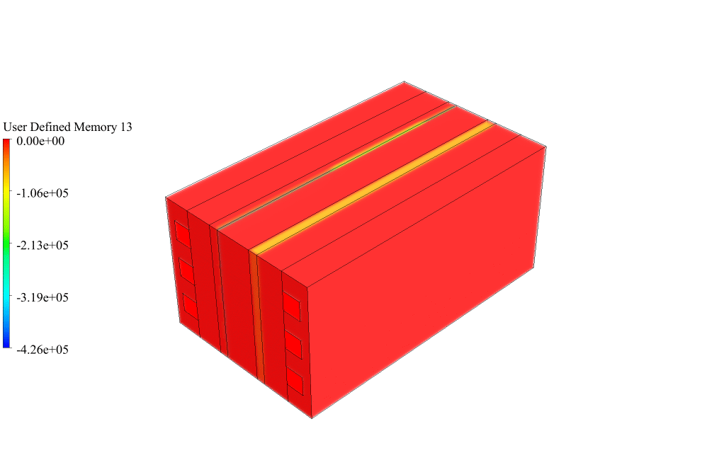
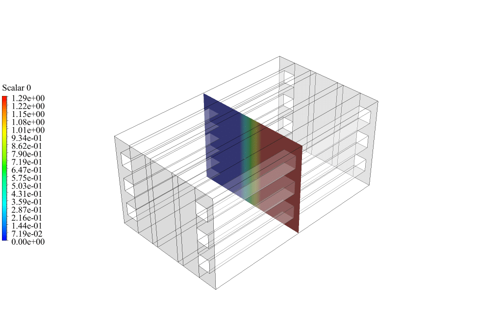
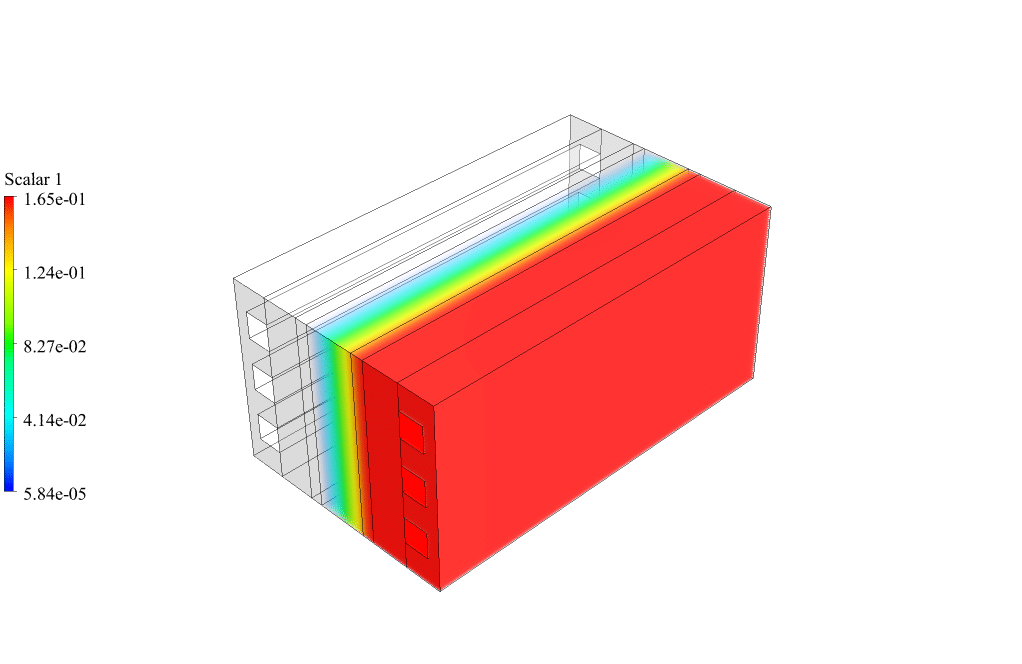
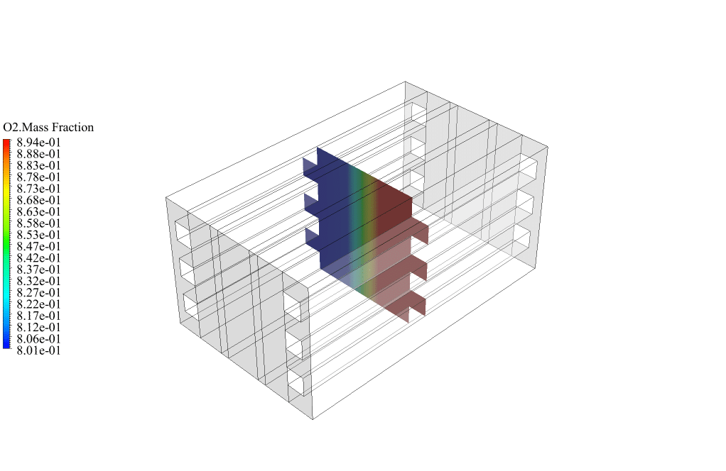
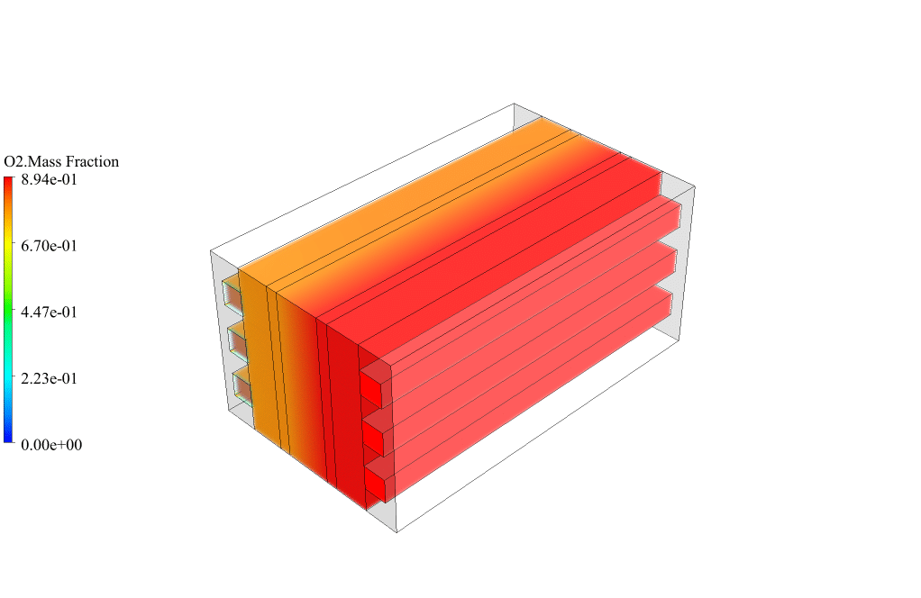
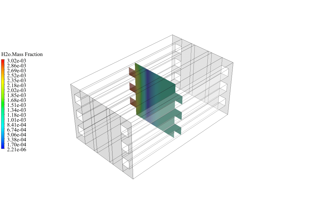
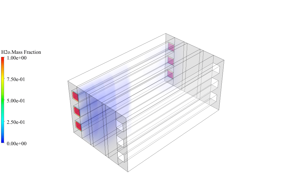
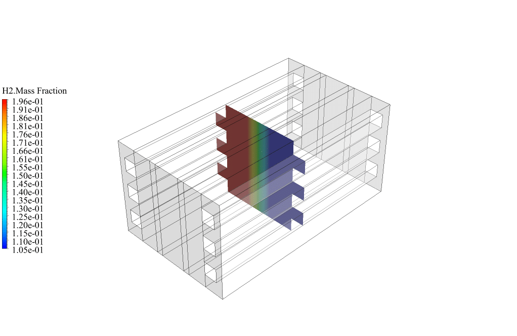
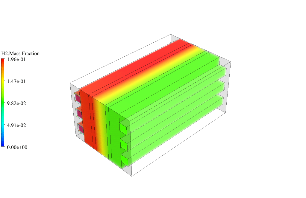
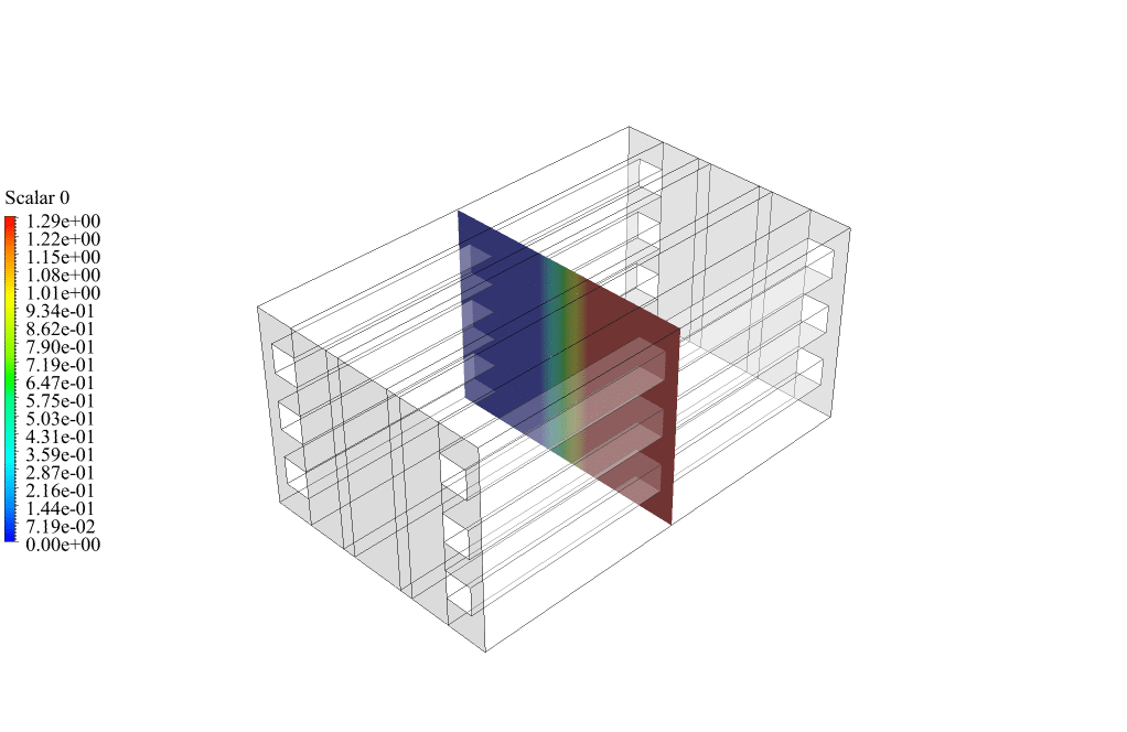
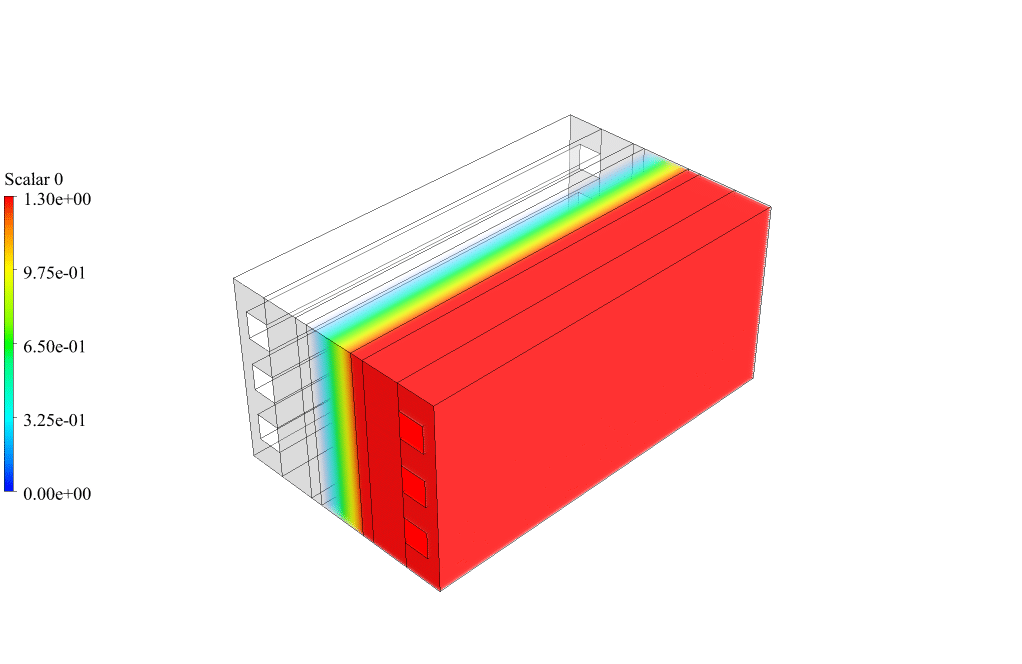
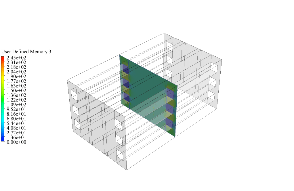
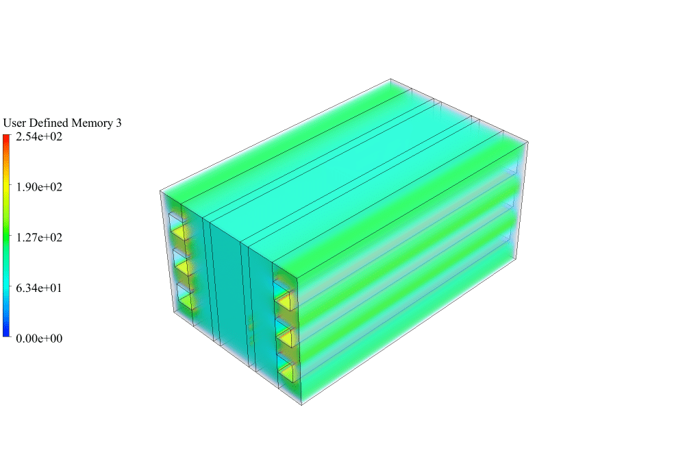
After conclusion, we have obtained the contours related to electric potential, protonic potential, current flux density magnitude, transfer current, and mass fraction of H2, O2, and H2O.
The H2, O2, and H2O mass fraction contours show that water vapor enters from the anode side, hydrogen is produced on the anode side, and oxygen is produced on the cathode side. This behavior is exactly according to the functional mechanism of the electrolysis system.
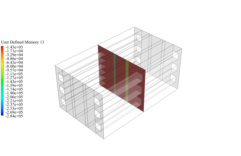
When we use the electrolysis model, some user-defined scalars (UDS) are enabled. Here, we obtained the contours of electric potential (scalar 0), and protonic potential (scalar 1). These contours show that the potential equations of the electrolysis model are solved correctly. Hence, the effect of electrons and protons in electrolyzer layers is understandable. Also, when we use the electrolysis model, several user-defined memories (UDM) are enabled. Here, we obtained contours of current flux density magnitude (user-defined memory 3) and transfer current (user-defined memory 13). These contours show that there is an electric current in the electrolyzer.


Reyna O’Reilly V –
I’m impressed with the level of detail in this simulation. There was no mention of any thermal effects being accounted for. Does the model include temperature dynamics too, or is it purely electrochemical?
MR CFD Support –
Thank you for your compliments and your interest in the Electrolysis simulation! The model primarily focuses on the electrochemical aspects including the representation of electric potential, protonic potential, and current density. However, if thermal effects are significant for the operation of the electrolyzer, they can be included in the simulation by activating energy equations within the ANSYS Fluent software along with the appropriate boundary conditions for heat transfer.
Aaron Gottlieb –
The detail in the electrolysis simulation is impressive. What aspects of this learning material stood out as particularly beneficial for understanding electrolysis process?
MR CFD Support –
Thank you for your positive feedback! We’re glad to hear that our Electrolysis CFD Simulation module provided deep insights into the process. We designed this material particularly to cover the detailed physics of electrolysis within an electrochemical cell, emphasizing the interaction between electric and protonic potentials, the distribution of species, and the resultant current densities. Visualizing the mass fraction contours of H2, O2, and H2O provides an intuitive grasp of the principles of matter transformation in the cell, and illustrates the effect of electrons and protons on the functioning of the electrodes. If you have any further questions or need a deeper understanding of any specific part of the simulation, do not hesitate to ask.
Bart Hermiston –
The instructions are clear, and the results showcase a successful and functional mechanism simulation of an electrolyzer using CFD. It’s fascinating to see how the potentials and currents behave in the system when visualized through the contour plots. The power of simulation to visualize and optimize such complex systems like a fuel cell electrolyzer is truly impressive.
MR CFD Support –
Thank you for your positive feedback! It’s great to hear that the clarity of instructions and the provided simulation results helped you to understand the complexities of the electrolyzer mechanism. We strive to deliver comprehensive simulations that are not only accurate but also insightful for our users. If you have any more questions or need further assistance with our products, please feel free to reach out.
Breanne Cruickshank –
The explanation of the Electrolysis CFD Simulation using ANSYS Fluent is superb. It helped me grasp the intricate details involved in modeling such a complex chemical process. The visualization of the electric and protonic potentials, as well as the current flux density magnitude, is quite insightful.
MR CFD Support –
Thank you for your positive feedback on our Electrolysis CFD Simulation product. We’re delighted to hear that the detailed simulations and visualizations were helpful and provided clarity on the complex physics of electrolysis processes. We always strive to create informative and functional training materials. If you have any more questions or require further assistance, don’t hesitate to reach out.
Prof. Sigmund Sporer –
I’m thrilled with the results obtained from the Electrolysis CFD Simulation. Seeing the contours for electric potential and the mass fractions of H2, O2, and H2O was very insightful and reinforced the theoretical knowledge I had. The detailed simulation perfectly demonstrated how the potential equations are correctly solved, and the impacts of electrons and protons in the electrolyzer layers are clear. Quite impressed by how well the CFD model visualizes the phenomenon!
MR CFD Support –
Thank you for your positive feedback! We are so glad to hear that you found the Electrolysis CFD Simulation results insightful and that they enhanced your understanding of the process. It’s great that the visualization met your expectations and provided clear and detailed insights. We appreciate you taking the time to compliment our product. If you have any further questions or need more information, please do not hesitate to reach out.
Cordelia Willms –
I’m impressed by the detailed analysis performed. Was the temperature distribution within the electrolyzer also a part of the simulation, and if so, how does it affect the efficiency of the electrolysis process?
MR CFD Support –
Yes, temperature distribution is typically a part of such simulations as it directly affects the efficiency of the electrolysis process. In ANSYS Fluent, temperature effects can be included in the electrolysis model to observe how heat is generated and dispersed within the system. The temperature influences reaction rates and ion transport, thus affecting the overall efficiency of the electrolyzer.