Erosion in the Bent Pipe CFD Simulation, Ansys Fluent Training
$100.00 $50.00 Student Discount
In this project, erosion in the bent pipe has been simulated and the results of this simulation have been investigated.
Click on Add To Cart and obtain the Geometry file, Mesh file, and a Comprehensive ANSYS Fluent Training Video.
To Order Your Project or benefit from a CFD consultation, contact our experts via email (info@mr-cfd.com), online support tab, or WhatsApp at +44 7443 197273.
There are some Free Products to check our service quality.
If you want the training video in another language instead of English, ask it via info@mr-cfd.com after you buy the product.
Description
Erosion Project Description
This simulation is modeling erosion in the bent pipe by a Two-way DPM Erosion Model to see the erosion rate in the pipe using ANSYS Fluent software. Working fluid is water liquid, and sand particles are DPM injections. Particles are inert and with no initial velocity.
Geometry & Mesh
The 3-D geometry of the present model is carried out using Design Modeler software.
The meshing of this present model has been generated by ANSYS Meshing software. The mesh grid is unstructured with no element quality lower than 0.53, and the total cell number is 448925. the figure below shows an overview of the performed mesh.
Erosion CFD Simulation
To simulate the present model, several assumptions are considered, which are:
- The solver is pressure-based.
- This Simulation is steady.
- The effect of gravity on the flow is considered to be -9.81 m.s-2 and along with the y-axis in the present model.
The following is a summary of the steps for defining the problem and its solution.
| Models | |||
| K-epsilon | Viscous model | ||
| Realizable | k-epsilon model | ||
| Scalable wall function | k-epsilon options | ||
| water | primary phase | ||
| sand | Particle | ||
| explicit | formulation | ||
| Boundary conditions | |||
| Velocity-inlet | inlet | ||
| Discrete phase pressure | escape | ||
| 44.8 | initial gauge pressure | ||
| 2 m/s | velocity magnitude | water | |
| Pressure outlet | outlet | ||
| Discrete phase condition | Escape | ||
| 0 | Supersonic gage pressure | water | |
| wall | wall | ||
| stationary wall | wall motion | ||
| Solution Methods | |||
| Phase coupled | pressure-velocity coupling | ||
| PRESTO! | pressure | ||
| first-order upwind | momentum | ||
| first-order upwind | specific dissipation rate | ||
| first-order upwind | volume fraction | ||
| Initialization | |||
| standard | initialization method | ||
| 2m/s | water velocity (0,y,0) | ||
| 0 m/s | particle velocity (x,y,z) | ||
Results
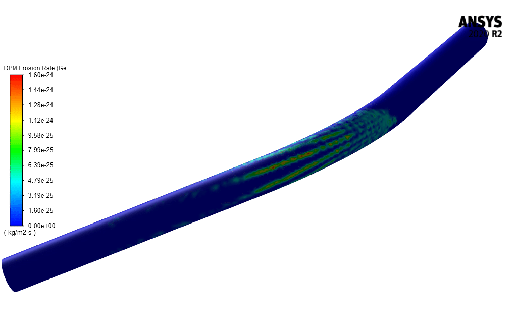
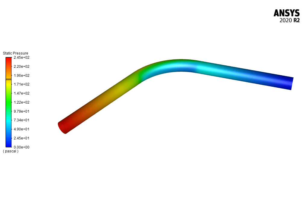
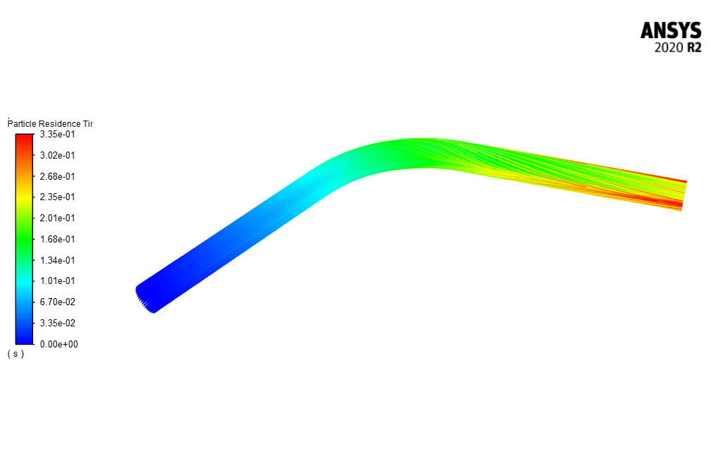
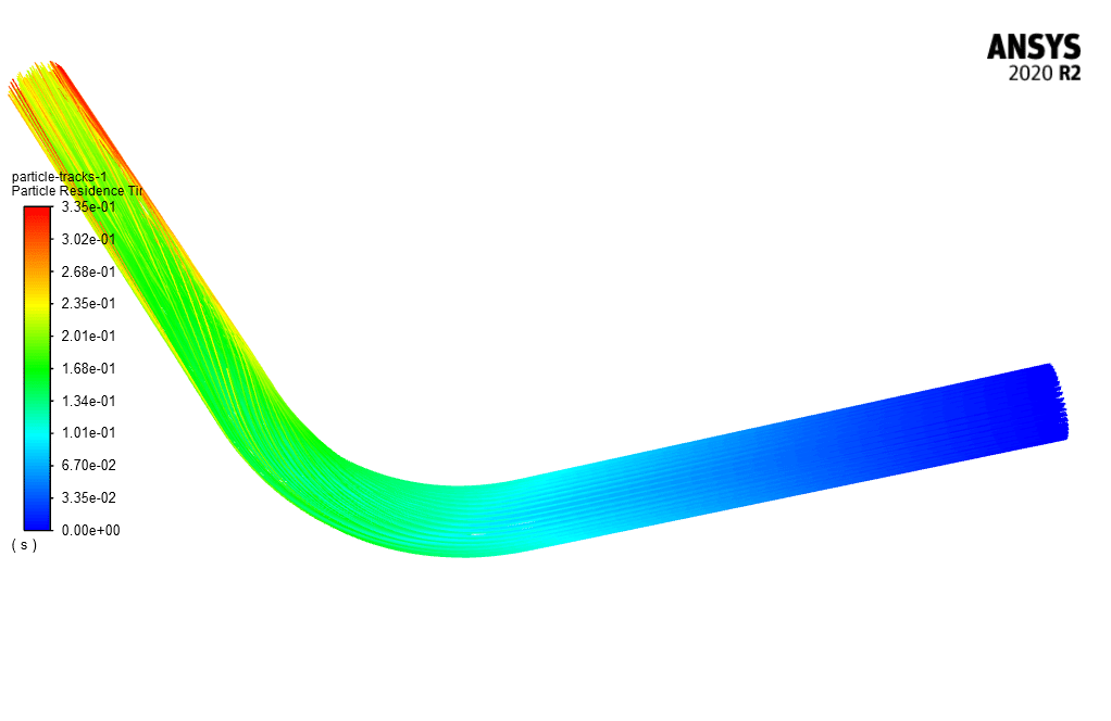
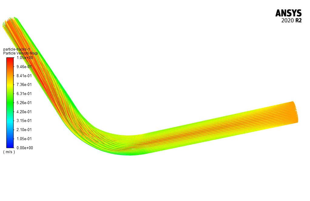
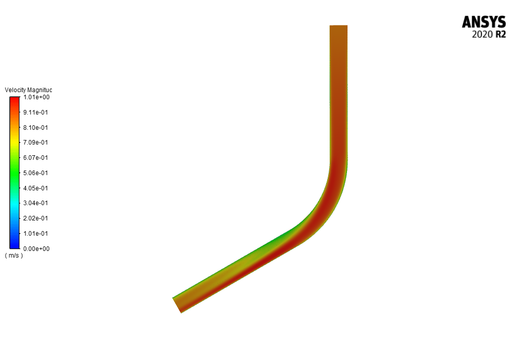
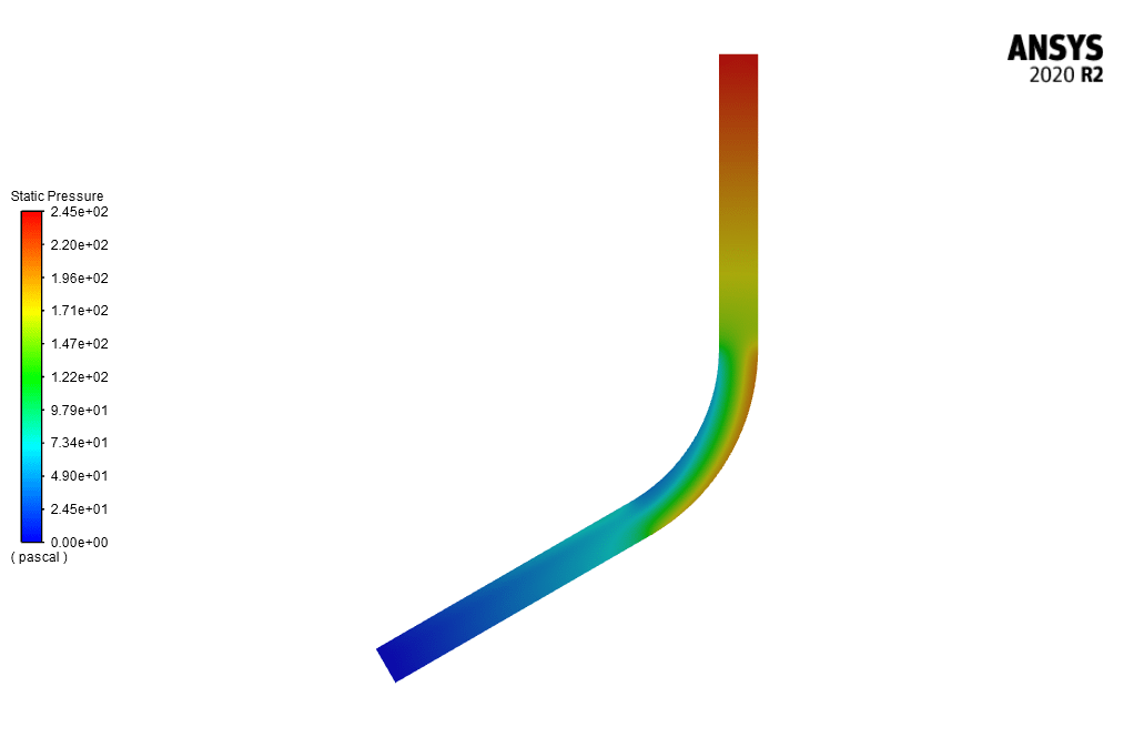
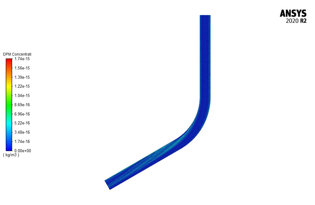
At the end of the solution process, two-dimensional and three-dimensional velocity, erosion rate, particle tracking counters are obtained. This 3-D simulation shows how sand particles erode the pipe from its bend. Also shows the effect of bend on pressure and velocity field on the bent pipe.
You can obtain Geometry & Mesh file and a comprehensive Training Movie that presents how to solve the problem and extract all desired results.




Horace Heller –
What is the size range of sand particles used in the DPM injections for the erosion simulation?
MR CFD Support –
The information regarding the exact size range of sand particles used in the DPM injections in the erosion simulation is not provided in the description above. However, to accurately model erosion, sand particle sizes would typically be chosen based on common size distributions found in the transported sediment of interest.
Miss Gerda Murray –
Can you explain if the erosion model accounts for different particle sizes or if it only simulates erosion from a uniform sand particle size?
MR CFD Support –
In the described simulation, the erosion rate is typically studied with the assumption of a uniform particle size for simplicity. However, ANSYS Fluent has the capability to simulate varying particle sizes through its DPM (Discrete Particle Model) to see how different sizes affect the erosion rate within the pipe.
Veronica Dach –
The provided explanation about erosion in the bent pipe simulation is comprehensive, but can you tell me more about how the erosion rate is calculated and what factors are taken into consideration?
MR CFD Support –
In this CFD simulation, the erosion rate is calculated using the Two-way Discrete Phase Model (DPM) in ANSYS Fluent which accounts for the impact of sand particles on the pipe walls. The factors considered include particle size, density, velocity at impact, incident angle, and material properties of the pipe. The calculation integrates these parameters to estimate the amount of material worn away from the pipe walls, using specific erosion models embedded in the software.
Miles Rodriguez III –
The description mentions using a Two-way DPM Erosion Model. Can you please explain what the two-way DPM means and its advantages in this type of erosion simulation?
MR CFD Support –
Two-way DPM (Discrete Phase Model) refers to a modeling approach where there’s an interaction between the discrete phase (in this case, the sand particles) and the continuous phase (the water flow). In erosion simulations, the two-way DPM allows for the calculations of the impact of the particles on the walls of the pipe as well as the influence of the fluid flow on the trajectory of the particles. This results in a more accurate prediction of erosion rates and patterns that would occur in the actual system.
Otis Lesch –
I purchased the Erosion in the Bent Pipe CFD Simulation training and it was incredibly detailed. I particularly found the particle tracking animations helpful for understanding erosion patterns. Great job on this one!
MR CFD Support –
Thank you for your kind words! We are thrilled to hear that you found the particle tracking animations helpful and that the details in our Erosion in the Bent Pipe CFD Simulation training met your expectations. It’s always our goal to provide comprehensive and easy-to-understand resources. If there’s anything else we can assist you with, please don’t hesitate to let us know. We look forward to serving you again!
Richard Lehner II –
The training materials and video were really detailed. I followed along and was able to grasp both the set up and the analysis of the CFD model effectively. I’m quite impressed with the clear representation of the erosion effects and how the bend influences the dynamics within the pipe. Well done MR CFD for another exemplary training product.
MR CFD Support –
Thank you so much for your positive feedback! We are thrilled to hear that our training materials and video guided you effectively through the CFD simulation process and helped you understand the influence of pipe dynamics and erosion effects. Your success is what we aim for, and we appreciate you choosing MR CFD. Looking forward to providing you with more quality learning experiences!
Daija Adams –
The training material for the bent pipe erosion simulation was exceptional! The inclusion of a detailed step-by-step video made the learning process so much easier and the unstructured mesh was well-optimized for accurate erosion rate predictions. Bravo on creating such an insightful and practical CFD training resource!
MR CFD Support –
Thank you for your kind words! We are thrilled to hear that you found our training material and video helpful for understanding the complex simulation of erosion in a bent pipe. It’s our pleasure to provide quality educational content that enhances learning and practical application. If you have any more questions or need further assistance, feel free to ask. Your success and satisfaction with our learning products are very important to us!
Bailee Koch –
I’m curious, does the erosion simulation take different particle sizes into account, and how does the particle size affect the results?
MR CFD Support –
In this erosion simulation, the effects of different particle sizes can be considered by defining multiple injections in the discrete phase model with various diameters for the sand particles. The particle size directly influences the impact energy and hence the erosion rate; larger particles usually result in increased erosion at the areas where they impact the pipe, especially at the bends where the flow changes direction rapidly.
Mr. Carol Becker –
Are there video explanations provided in the training on how to set up the DPM model and analyze the results for this kind of simulation?
MR CFD Support –
Yes, the comprehensive Training Movie included with the product provides a detailed walkthrough on setting up the Discrete Phase Model (DPM) used for simulating particle erosion as well as step-by-step guidance on analyzing the simulation results for this erosion in the bent pipe scenario.
Peter Muller –
The training materials sound comprehensive, but I’m curious to know if the simulation accounts for the change in sand concentration as the erosion process progresses?
MR CFD Support –
The primary focus of the simulation using ANSYS Fluent’s DPM model is to assess the erosion rate in a bent pipe. Various assumptions, such as inert sand particles and considerations for gravity, allow an approximation of erosion effects. However, gradual changes in sand concentration may not be explicitly modeled. The concentration remains fixed for steady simulation evaluations. Such dynamic concentration changes typically require a transient simulation for more detailed insights.
Marta Jakubowski –
I really enjoyed learning from the CFD simulation about erosion in bent pipes. It was intriguing to see how different particle sizes and velocities contributed to the rate of erosion. The training movie made the complex concepts much easier to understand.
MR CFD Support –
Thank you for the positive feedback on the Erosion in Bent Pipe CFD Simulation training. It is wonderful to hear that you found the educational materials and the training movie helpful in understanding the complex phenomena of erosion in pipes. We are thrilled that our product met your expectations and enhanced your learning experience.
Shirley Price –
The training materials seem comprehensive, but could you elaborate on how it shows the effect of the bend on the pressure and velocity fields?
MR CFD Support –
In the erosion simulation for the bent pipe, the effect of the bend on the pressure and velocity fields is captured by carefully monitoring the distributions of these quantities within the system. ANSYS Fluent allows us to visualize these fields through detailed two-dimensional and three-dimensional contours. The pressure and velocity changes are most significant at and downstream from the bend due to the flow’s altered direction and increased turbulence. Through such simulations, trainees can observe and analyze these effects, thereby understanding the complexities of flow behavior in the real-world scenarios represented.
Amira O’Kon –
Wonderful review! The effects of erosion in bent pipes are critical in industrial applications and understanding the simulation parameters and results can be greatly beneficial for engineers and designers. Thank you for providing an interactive Training Movie and additional details with the Geometry & Mesh files!
MR CFD Support –
Thank you for your kind feedback! We’re thrilled to hear that our training materials and simulation insights were helpful to you. Our team at MR CFD is always committed to providing high-quality, user-friendly learning experiences for valuable real-world applications. We appreciate your review and look forward to serving any further learning needs you might have!
Kelsie Crona –
How precise can the erosion rate predictions be in this type of CFD simulation using ANSYS Fluent? Does it account for material properties of the pipe?
MR CFD Support –
In CFD simulations using ANSYS Fluent, the erosion rate predictions can be quite precise if all relevant physical phenomena and material properties are accurately modeled. The Two-way DPM Erosion Model takes into account not only the flow characteristics but also the material properties of the pipe, such as hardness and ductility, which influence the erosion rate. Proper calibration with experimental data can enhance the prediction accuracy.
Dr. Tanner Kautzer IV –
The training for erosion simulation sounds thorough! The step-by-step methodology is sure to pave the way for learners to fully grasp the concept.
MR CFD Support –
Thank you for your kind words! We’re thrilled to hear that you found our erosion simulation training to be comprehensive and effective. If there’s anything else you’d like to learn or if you have further questions, please let us know!
Lauren Smitham –
Fantastic explanation of the erosion simulation in a bent pipe! The detailed step-by-step methodology provides clarity on how you used the DPM erosion model to assess the system. I’m excited to have learned how the particle tracking counters operate and the manner in which the erosion impacts are demonstrated through the simulation.
MR CFD Support –
Thank you for your kind words! We’re thrilled to hear that you found our simulation tutorial on erosion in bent pipes informative and easy to understand. We strive to provide comprehensive and detailed explanations to equip our users with the knowledge to carry out effective CFD simulations. Your positive feedback is much appreciated!
Sean Jacobs –
I am really impressed with the detailed results of the erosion in the bent pipe study!
MR CFD Support –
Thank you for the positive feedback! We are glad you’re impressed with the study and found the detailed results informative and useful. If you have any questions or need further assistance with our simulations or CFD analysis, feel free to reach out!
Miss Kristy Ruecker IV –
Terrific simulation of erosion in pipe bends; your approach enables deeper understanding of material degradation for industry applications.
MR CFD Support –
We’re sincerely grateful for your positive feedback! Ensuring comprehensive understanding for practical industry applications is at the core of our training product design. Thank you for your acknowledgment, and we’re here if you need further support with your CFD endeavors!
Prof. Quinn Jenkins II –
The training material mentions that the initial velocity of sand particles is set to zero. How can particles cause erosion without an initial velocity? Does the water flow impart sufficient momentum to them?
MR CFD Support –
The initial condition of zero velocity for the sand particles means that they start without any predefined velocity, but once introduced into the flow field, the flowing water accelerates them. These particles then begin to follow the water flow, which imparts sufficient momentum and causes them to erode the pipe material, especially at the bends. The DPM model within ANSYS Fluent calculates the interactions and resulting erosion as the particles gain velocity from the water flow.
Prof. Shanny Greenholt MD –
The description mentions gravity having an effect on the flow. How does this impact the erosion patterns observed in the bent pipe?
MR CFD Support –
In the simulation, gravity is taken into account to more accurately represent real-life conditions in which the pipe might be oriented vertically or on an incline. Gravity affects how the sand particles settle and impact the pipe walls, which in turn influences the distribution and intensity of the erosion. By considering gravity, we can observe more realistic erosion patterns, notably the areas where the particles strike the pipe more forcefully due to gravity acceleration, hence experience higher rates of erosion.
Dr. Neoma Pfannerstill –
I found the erosion rate data in this simulation particularly interesting. Could you please elaborate on the factors that directly influenced the erosion patterns within the pipe bend?
MR CFD Support –
The erosion patterns within the pipe bend are influenced by several factors, such as the velocity of the water, the size, material, and injection rate of the sand particles, the bend curvature of the pipe, and the interaction between the fluid flow and the particulate matter. The bend increases turbulence and changes the flow path, causing areas of higher velocity where the particles can impact the pipe wall more frequently or with greater force, leading to varying erosion rates, especially in areas where the flow changes direction sharply.
Kim Robel –
Just received my erosion simulation training for Ansys Fluent, and I have to say it’s impressive! Clear explanations and meticulous attention to the modeling of sand particle behavior within the bent pipe. The real-time erosion impact visualization is top-notch, and I find the particle tracking counters particularly useful for understanding the erosion rate at critical points in the pipeline.
MR CFD Support –
Thank you so much for your positive feedback! We are delighted to hear that you found the training helpful and that the visualizations and particle tracking enhanced your understanding of the erosion process within the bent pipe simulation. If you ever have any questions or need further support, feel free to reach out.
Prof. Adam Trantow DDS –
The training product seems comprehensive. Could you please provide more details about how the erosion rate is calculated within the simulation?
MR CFD Support –
In this CFD simulation, the erosion rate is calculated using the Two-way DPM (Discrete Phase Model) Erosion Model, where the impacts of sand particles on the pipe walls in the flow stream are tracked, and the erosion rates at different locations are computed based on the particle properties, wall material properties, collision parameters, and particle-wall interactions.
Lorine Paucek –
What steps should I follow to ensure an accurate simulation of erosion in a pipe like the one described?
MR CFD Support –
To ensure an accurate simulation of erosion in the pipe, please follow the set up outlined: choose the Two-way DPM Erosion Model; assume a pressure-based steady-state simulation with the effect of gravity; use the K-epsilon Realizable model for turbulence with scalable wall functions; accurately define boundary conditions such as velocity at the inlet and pressure outlet; apply the correct initial velocities and pressures; and finally, use an adequate mesh with a good quality metric. Choose appropriate discretization schemes and initialization methods for the water and particles. Once completed, post-process the results to evaluate erosion patterns and validate against expected physical behavior.