FCC Regenerator for Coke Combustion, Ansys Fluent CFD
$220.00 $110.00 Student Discount
- Reactors with risers. This resulted in successfully modeling the FCC reaction-regeneration system in a single CFD example
- The 3D virtual full-loop CFD simulation provided a detailed and comprehensive perspective of the reaction regeneration system’s performance
- The gas-solid interactions inside the FCC regenerator can be simulated using the Eulerian-Eulerian method
- The solid phase was treated using the Eulerian granular flow model
- The species transport model was implemented to monitor several chemical species
To Order Your Project or benefit from a CFD consultation, contact our experts via email (info@mr-cfd.com), online support tab, or WhatsApp at +44 7443 197273.
There are some Free Products to check our service quality.
If you want the training video in another language instead of English, ask it via info@mr-cfd.com after you buy the product.
Description
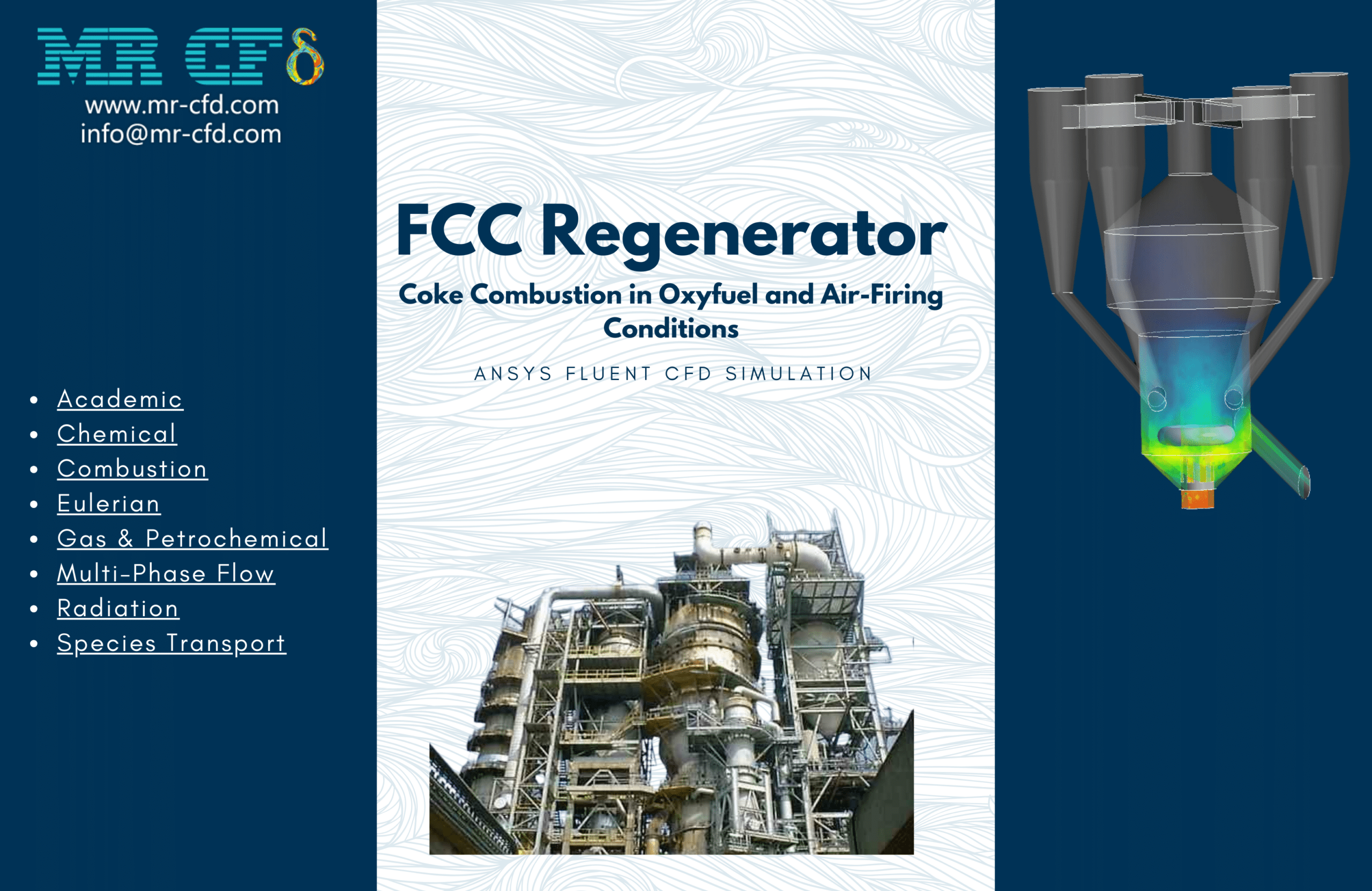
FCC Regenerator for Coke Combustion in Oxyfuel and Air-Firing Conditions, Ansys Fluent CFD simulation
description
One of the most significant conversion techniques utilized in refineries worldwide is fluid catalytic cracking (FCC). Propylene, diesel, gasoline, and other valuable products are produced by converting heavy oil feed with a high boiling temperature. The catalyst is continuously replenished in the FCC Regenerator process because coke deposits on it during the catalytic conversion and deactivates it. Because it directly affects product yields, the regeneration stage is crucial. Burning coke also produces NOx and SOx emissions, essential to measure and significantly impact the reactor structure, bed hydrodynamics, and operating parameters. Understanding the hydrodynamics and kinetics of the regenerator is crucial for all of these reasons. Reactors with risers. This resulted in successfully modeling the FCC Regenerator system in a single CFD example. The 3D virtual full-loop CFD simulation provided a detailed and comprehensive perspective of the reaction regeneration system’s performance, which is helpful for the FCC Regenerator unit’s operation and optimization. The industrial data and the principal projected findings agreed well.
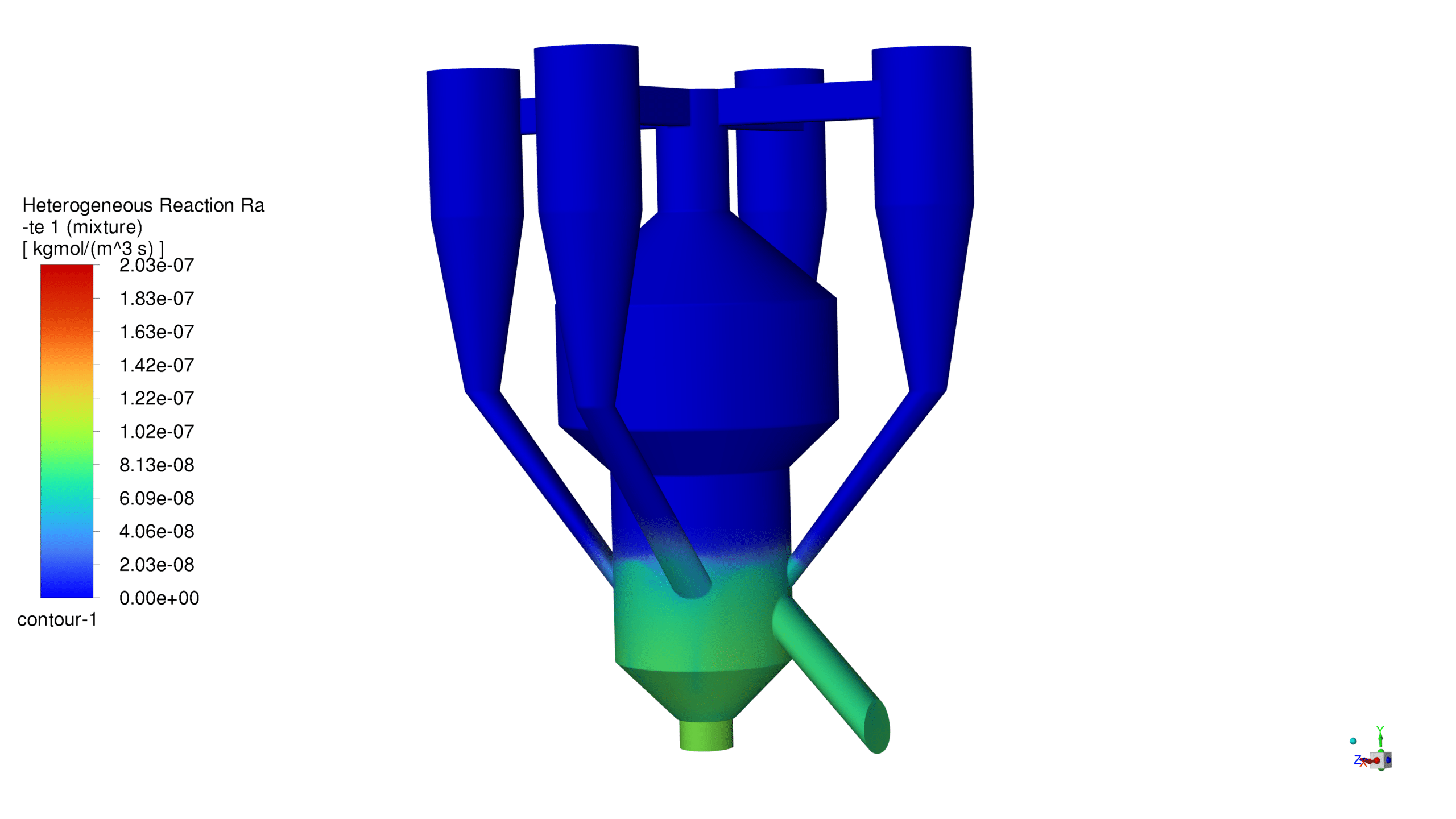
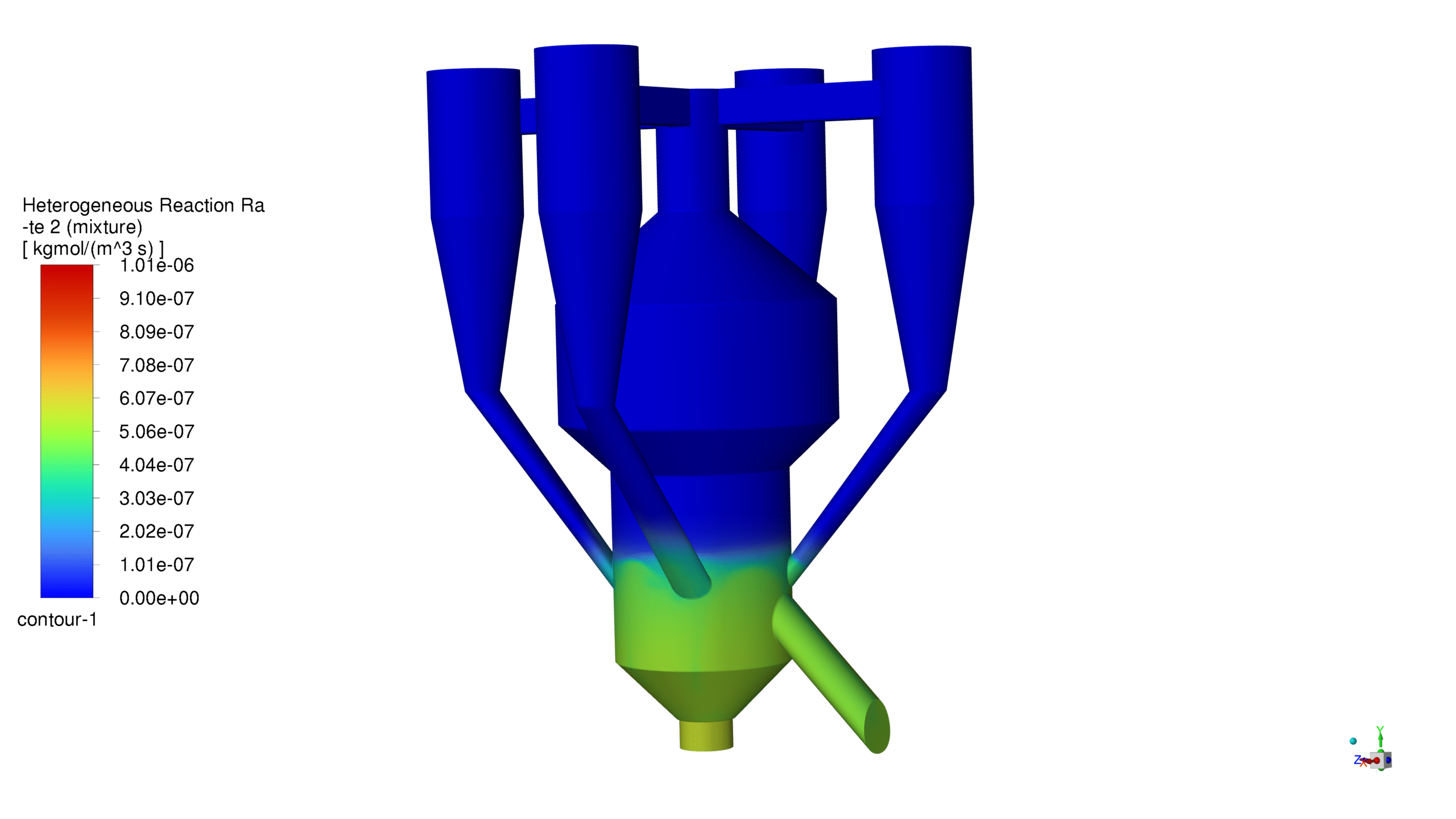
This study’s crucial component is incorporating an improved kinetic model that considers diffusion effects and both complete (C + O2 = CO2) and incomplete combustion (C + O2 = CO) reactions of coke.
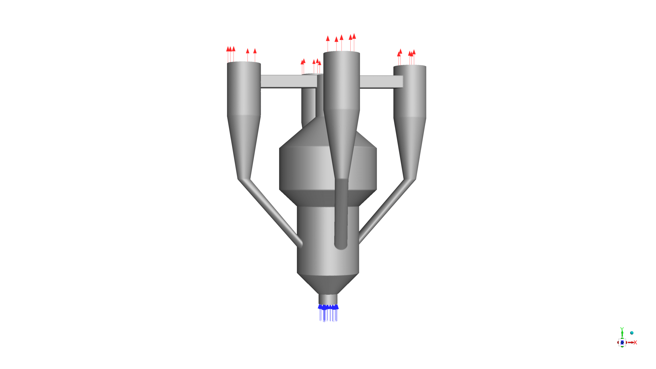
The 3-D geometry of the present model is carried out using space claim software. The geometry consists of a coke inlet, air inlet, gas outlet, and catalyst outlet. The meshing of this present model has been generated by ANSYS Meshing software. The mesh grid is unstructured, and the total cell number is 1,361,360.
Methodology
The gas-solid interactions inside the FCC regenerator can be simulated using the Eulerian-Eulerian method. To simulate the kinetics of coke oxidation, CO and CO2 are included as products in a multiple-surface-reaction model.
The solid phase was treated using the Eulerian granular flow model, which considers granular flow characteristics and particle-particle interactions.
The species transport model was implemented to monitor several chemical species’ concentration distributions and transport across the domain. This method makes examining species mixing, diffusion, and reaction mechanisms possible. The continuity and momentum equations were solved with the governing equations for species movement. The Arrhenius reaction rate model was used to determine the kinetics of the chemical reaction.
The Discrete Ordinates (DO) radiation model was implemented in the regenerator section to accurately account for the radiative heat transfer between the hot catalyst particles and surrounding gases.
This model offers a realistic depiction of the system’s chemical kinetics and successfully captures the temperature dependency of the reaction rates.
Results
Here’s a detailed analysis of your FCC reactor simulation results in complete sentences:
Mass Concentration Distribution:
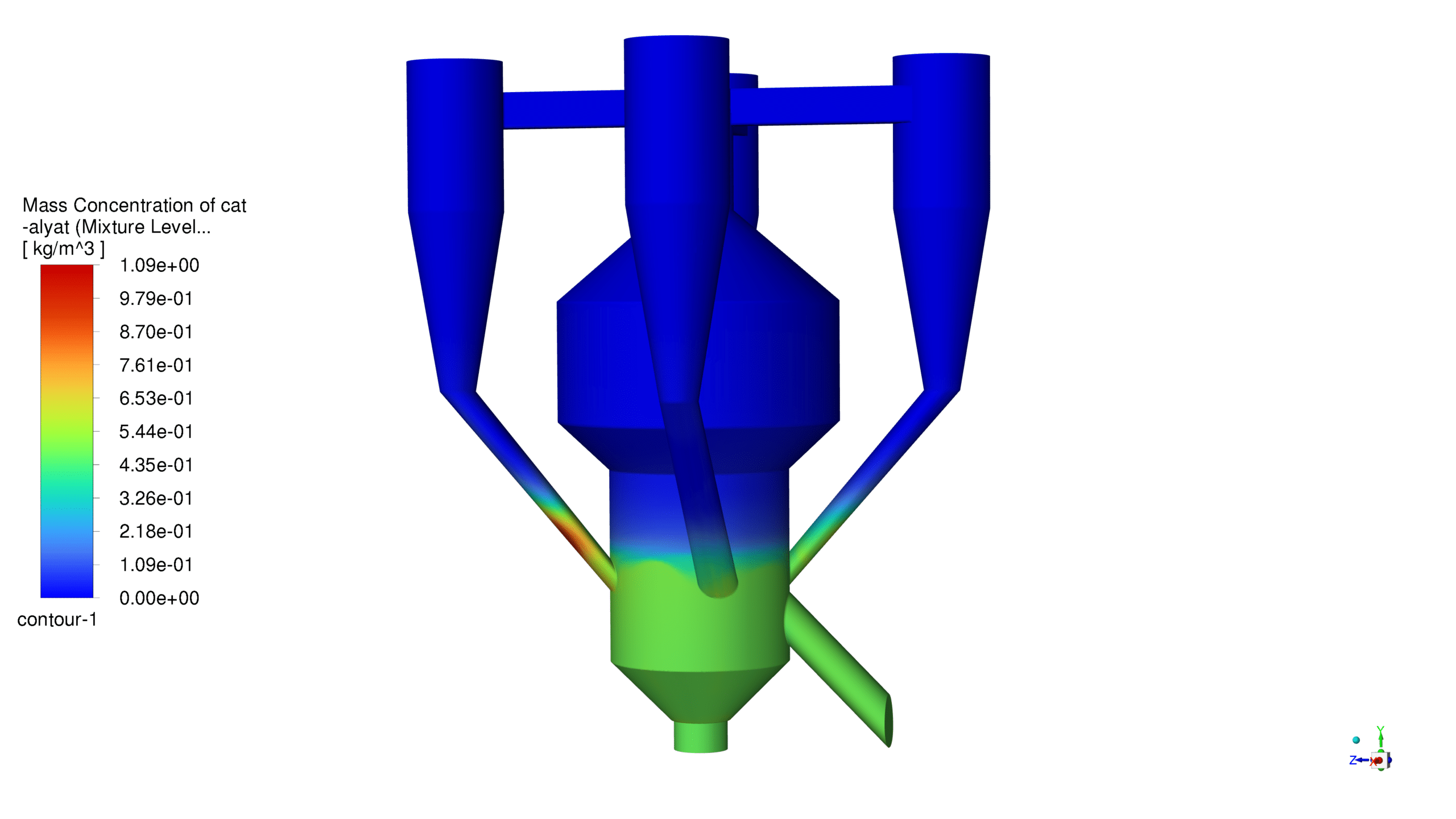
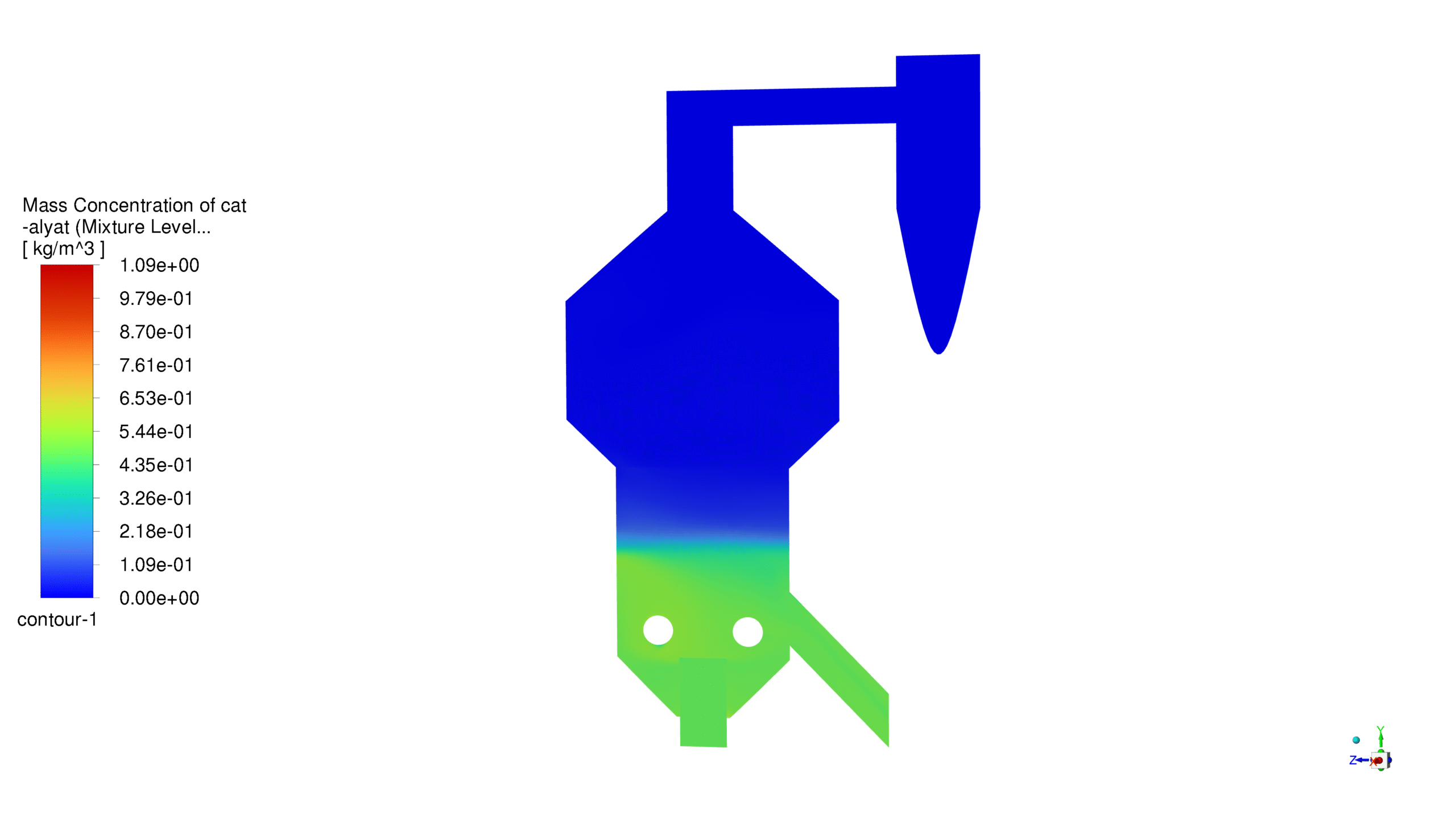
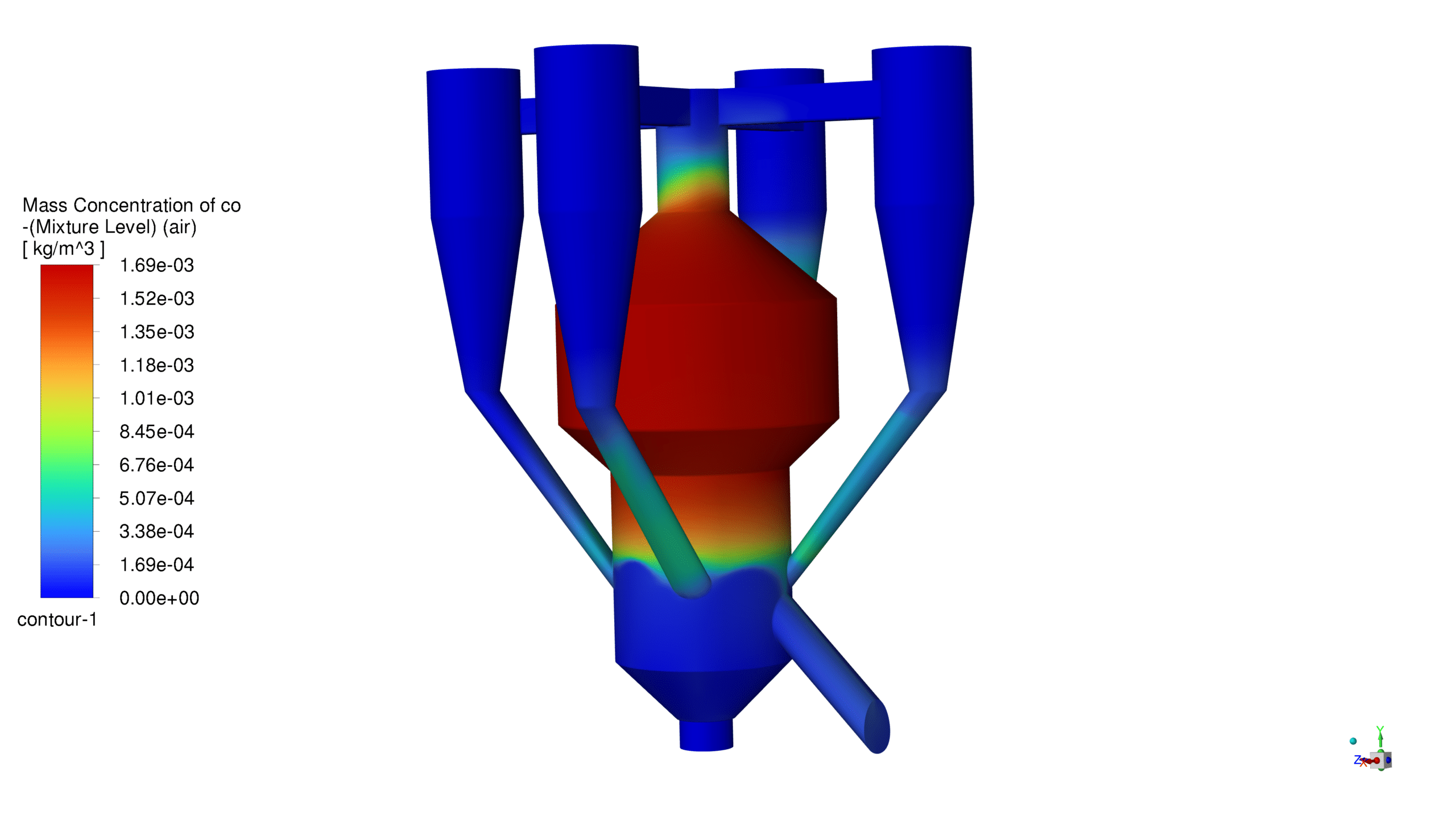
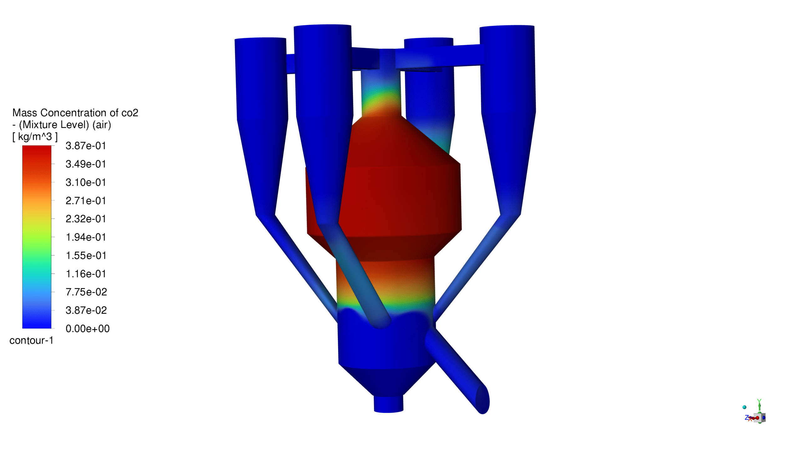
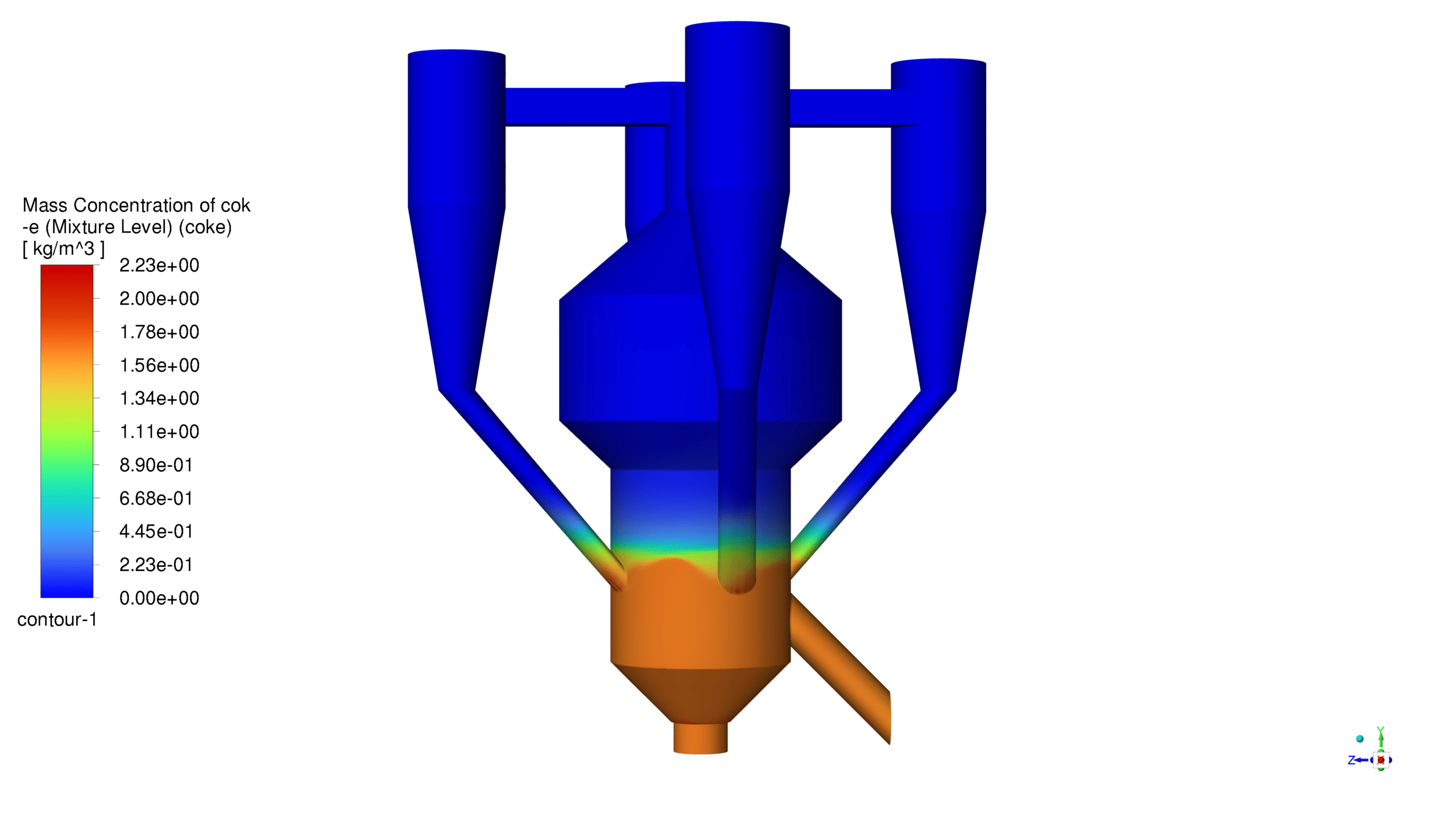
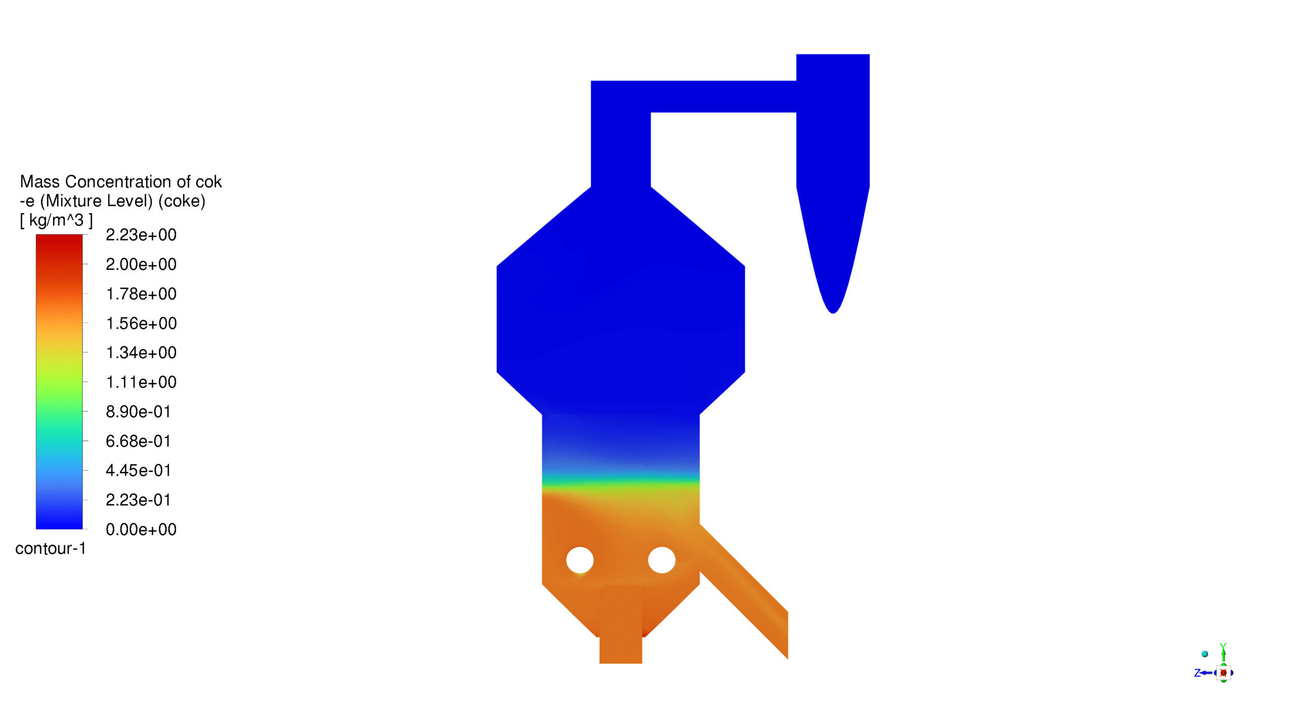
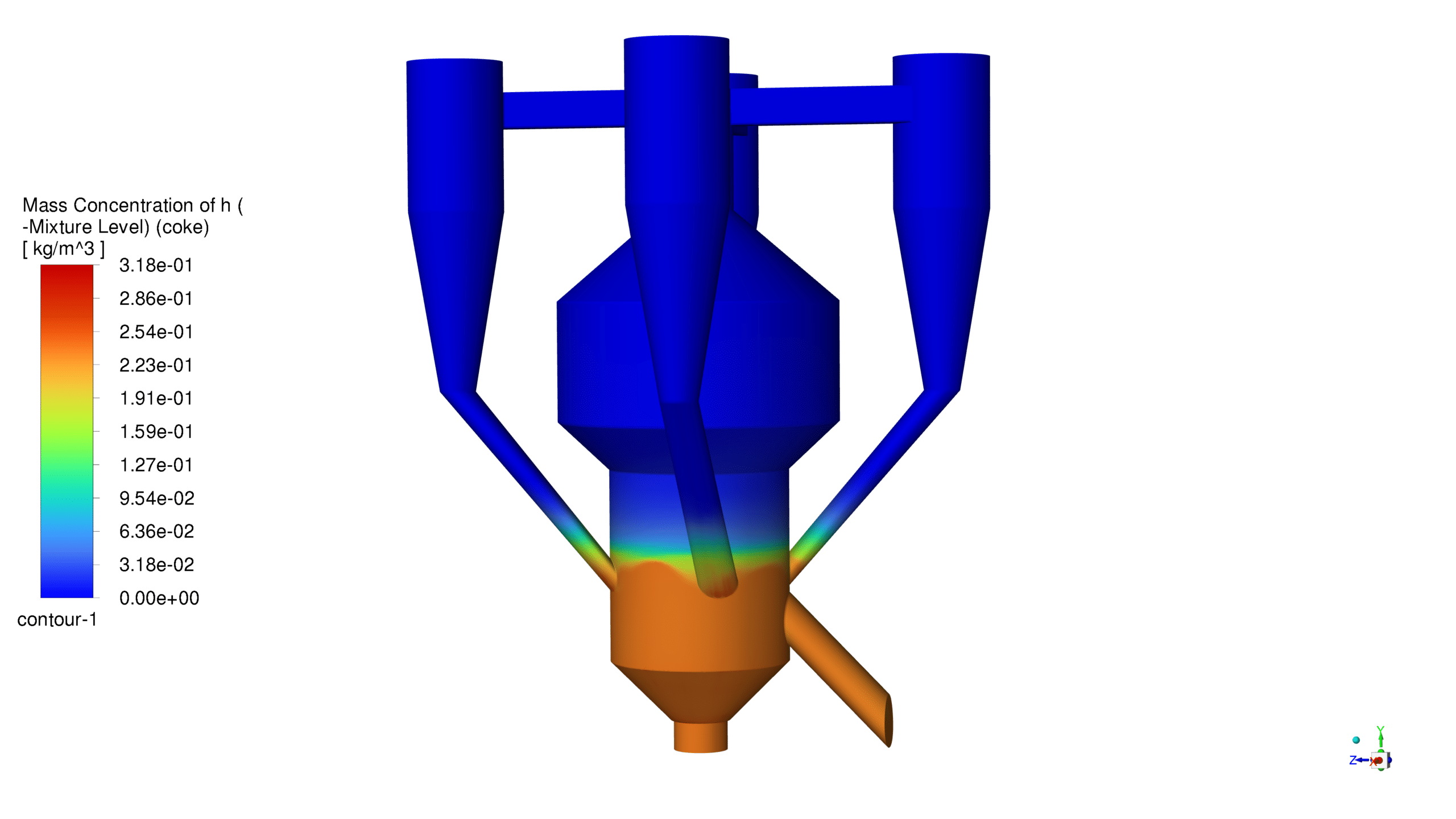
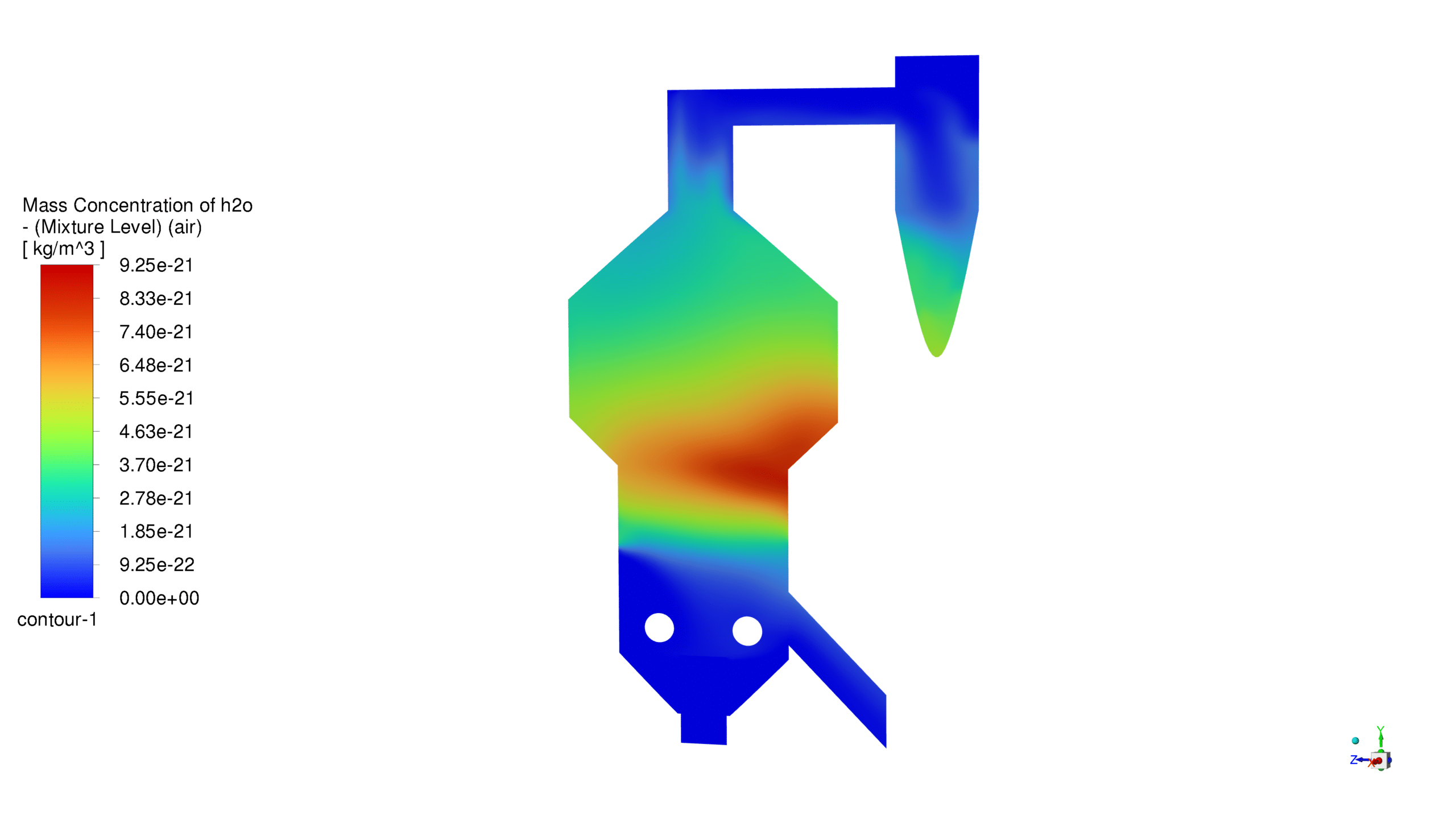
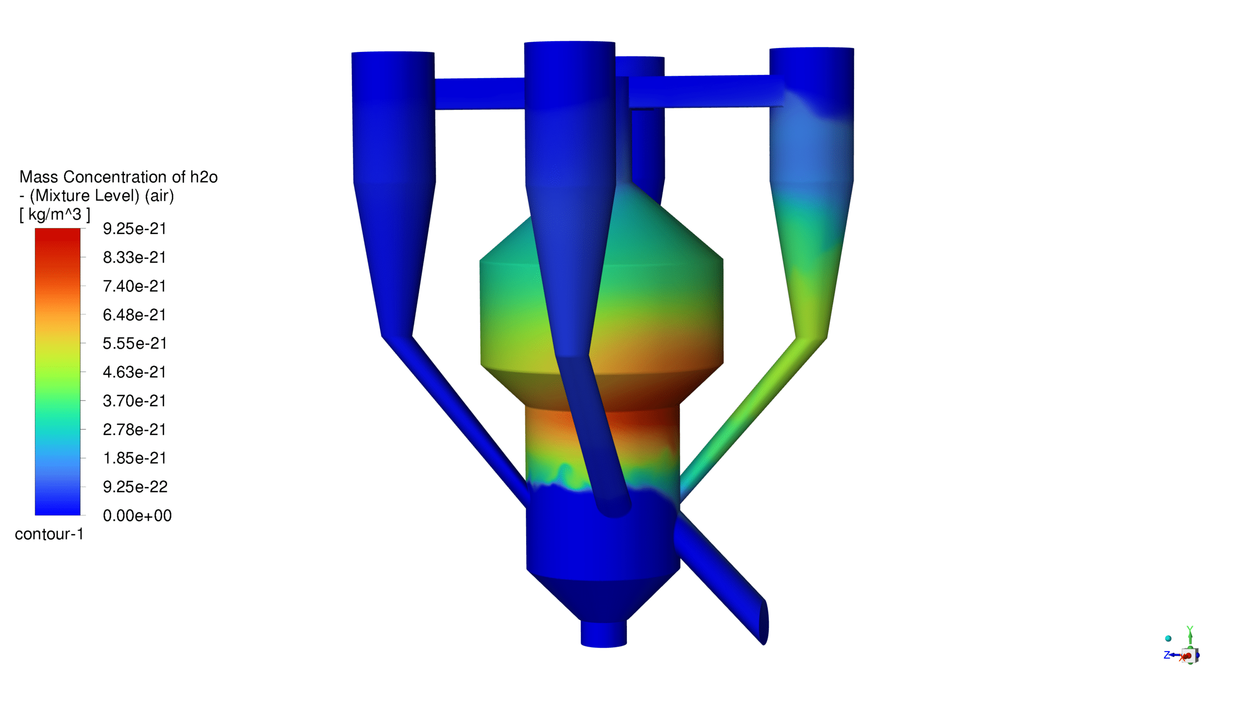
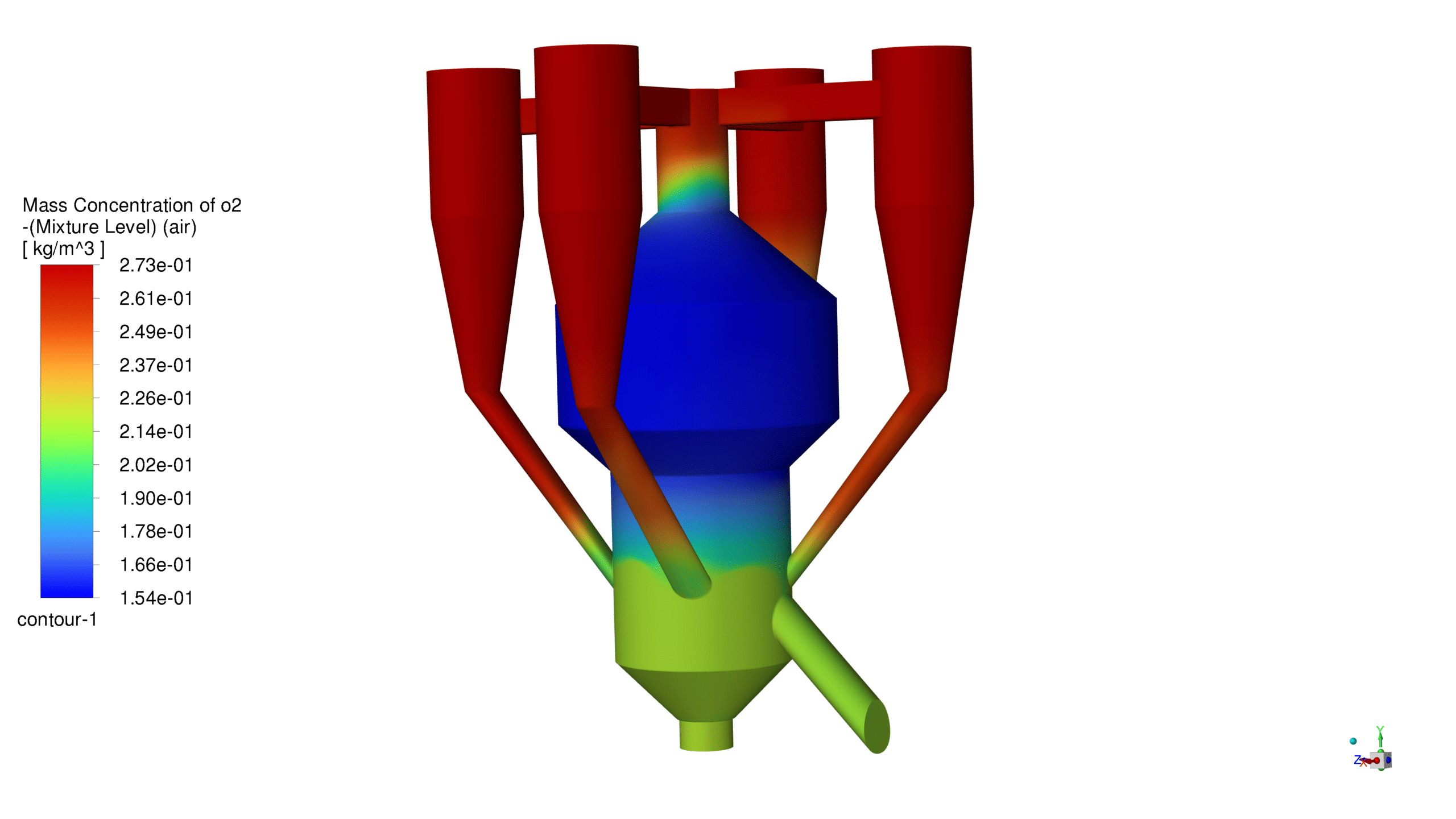
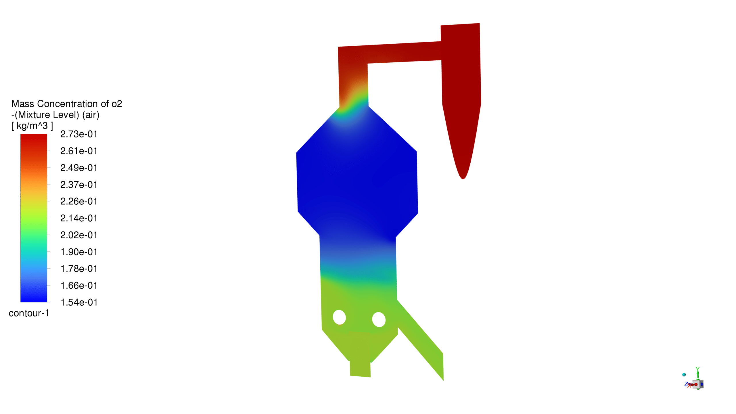
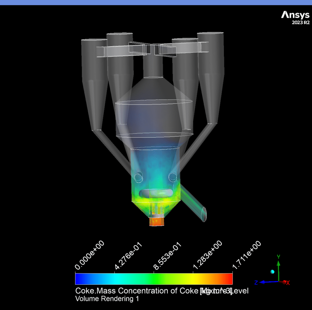
The catalyst concentration shows its highest value of 1.09 kg/m³ in the lower section of the reactor, with a gradual decrease towards the upper regions. The CO production demonstrates a maximum concentration of 1.69e-03 kg/m³ in the central reaction zone, indicating active catalytic conversion. Carbon dioxide reaches its peak concentration of 3.87e-01 kg/m³ in the main reaction zone, confirming successful oxidation processes. The coke formation is most prominent in the bottom section, with a maximum concentration of 2.23 kg/m³.
Temperature Profile:
The reactor exhibits a temperature range from 300K to 753K, with the highest temperatures observed in the reaction zone. This temperature distribution effectively supports the endothermic cracking reactions while maintaining catalyst activity. The gradual temperature gradient from bottom to top ensures proper heat distribution throughout the reactor.
Pressure Distribution:
The static pressure varies between -93.2 Pa and 92.9 Pa across the reactor volume. This pressure gradient creates favorable conditions for particle suspension and ensures proper fluid dynamics within the system. The pressure distribution pattern supports the upward movement of catalyst particles and maintains stable operation.
Velocity Analysis:
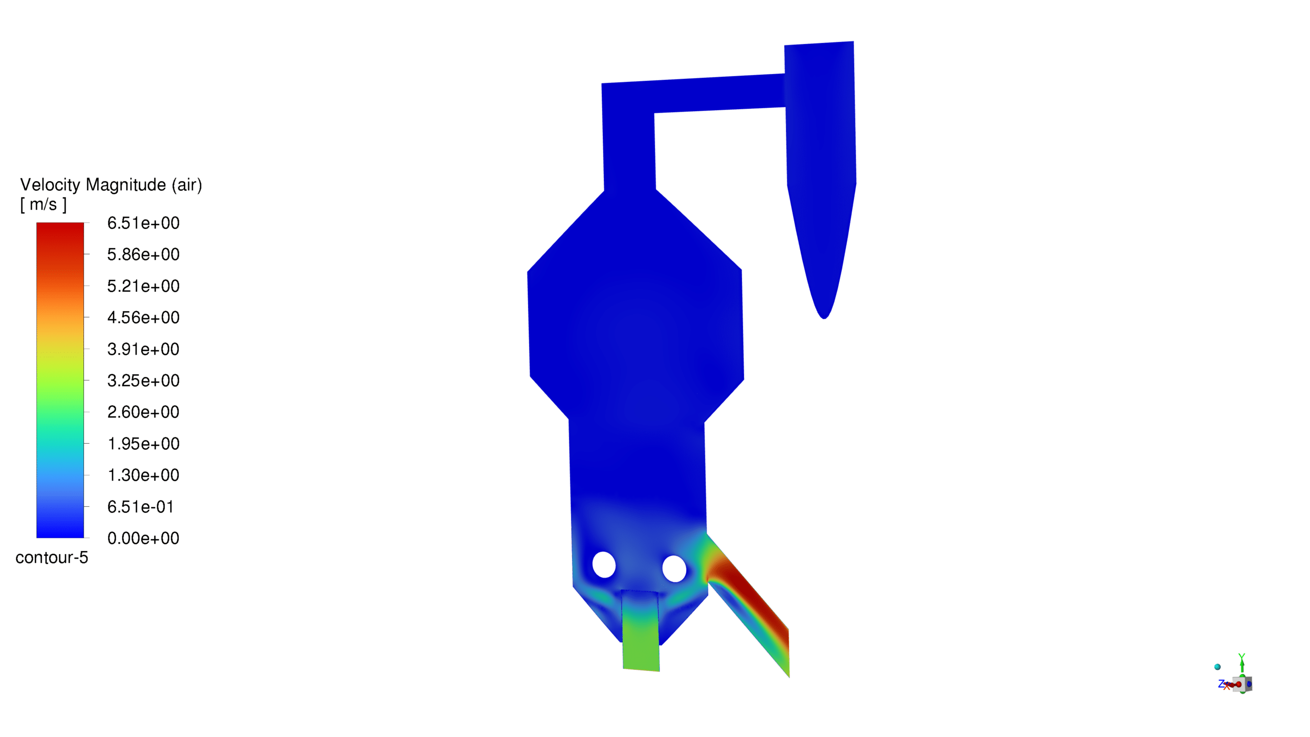
The velocity magnitude reaches a maximum of 6.51 m/s, with higher velocities particularly noticeable in the riser section. This velocity profile ensures adequate particle suspension and promotes efficient contact between the catalyst and feedstock. The flow pattern indicates good mixing characteristics and appropriate reaction residence time.
Mass Fraction Profile:
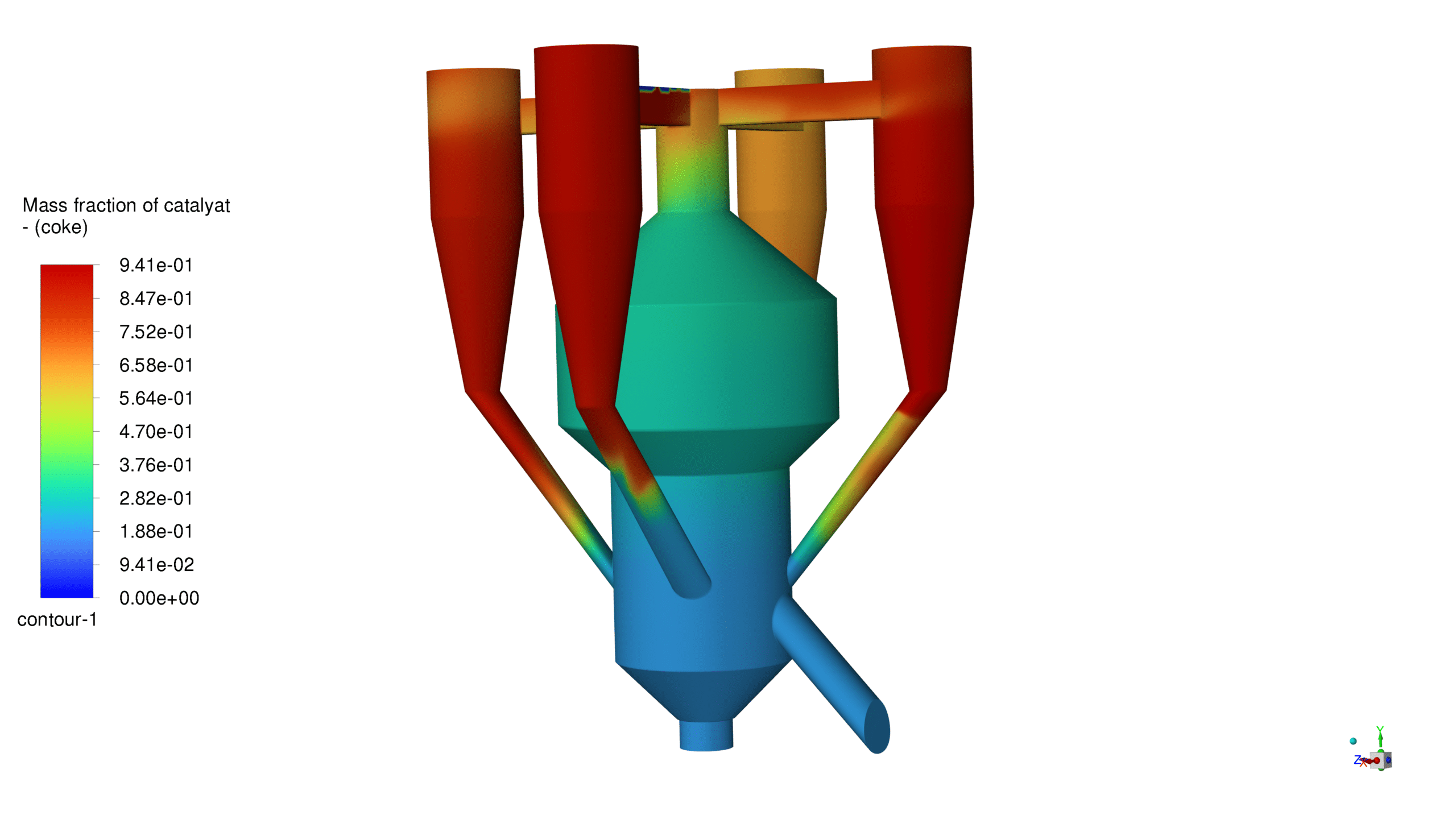
The catalyst mass fraction shows a well-distributed pattern, with higher concentrations in the lower regions gradually decreasing upward. This distribution pattern confirms adequate catalyst circulation and utilization throughout the reactor volume. The results validate the reactor’s design for optimal catalyst-feedstock contact and reaction efficiency.





Reviews
There are no reviews yet.