Fluid-Structure Interaction over HAWT Turbine Vibration (two-way)
$300.00 $150.00 Student Discount
- this report presents a FSI analysis of a HAWT using CFD.
- The geometry was created using ANSYS Design Modeler, and meshing was performed with ANSYS Meshing, resulting in a high-fidelity model with 3,465,821 cells.
- The simulation leverages (MRF) approach for rotating domains and dynamic mesh methods to capture the complex fluid-structure interactions.
- A two-way FSI approach was employed to capture the mutual interaction between the fluid flow and the structural deformation of the turbine blades.
To Order Your Project or benefit from a CFD consultation, contact our experts via email (info@mr-cfd.com), online support tab, or WhatsApp at +44 7443 197273.
There are some Free Products to check our service quality.
If you want the training video in another language instead of English, ask it via info@mr-cfd.com after you buy the product.
Description
Introduction
This report presents a comprehensive Fluid-Structure Interaction (FSI) analysis of a HAWT using advanced computational methods. FSI is a multiphysics approach that couples the principles of computational fluid dynamics (CFD) with structural mechanics to provide a holistic understanding of how fluid forces affect structural deformation and vice versa. This bidirectional coupling is particularly crucial in wind turbine design, where the flexible nature of large blades can significantly influence aerodynamic performance and structural integrity.
Also a one-way simulation of Fluid-Structure Interaction over HAWT Turbine was previously conducted,
The geometry was created using ANSYS Design Modeler, and meshing was performed with ANSYS Meshing, resulting in a high-fidelity model with 3,465,821 cells.
Methodology
The simulation leverages advanced techniques such as the Multiple Reference Frame (MRF) approach for rotating domains and dynamic mesh methods to capture the complex fluid-structure interactions.
A two-way Fluid-Structure Interaction (FSI) approach was employed to capture the mutual interaction between the fluid flow and the structural deformation of the turbine blades. The simulation utilized the following settings:
Inlet velocity: 25 m/s
Operating pressure: 101,325 Pa
Turbine rotation speed: 12 RPM
Result
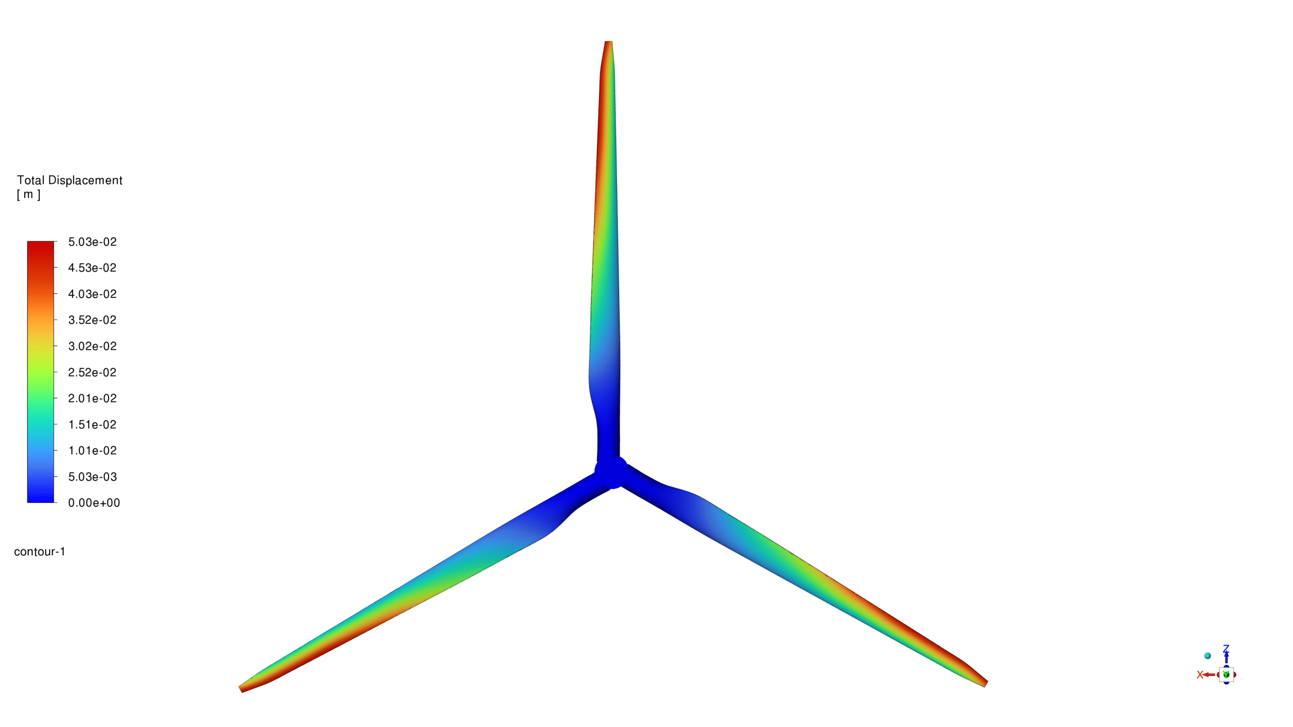
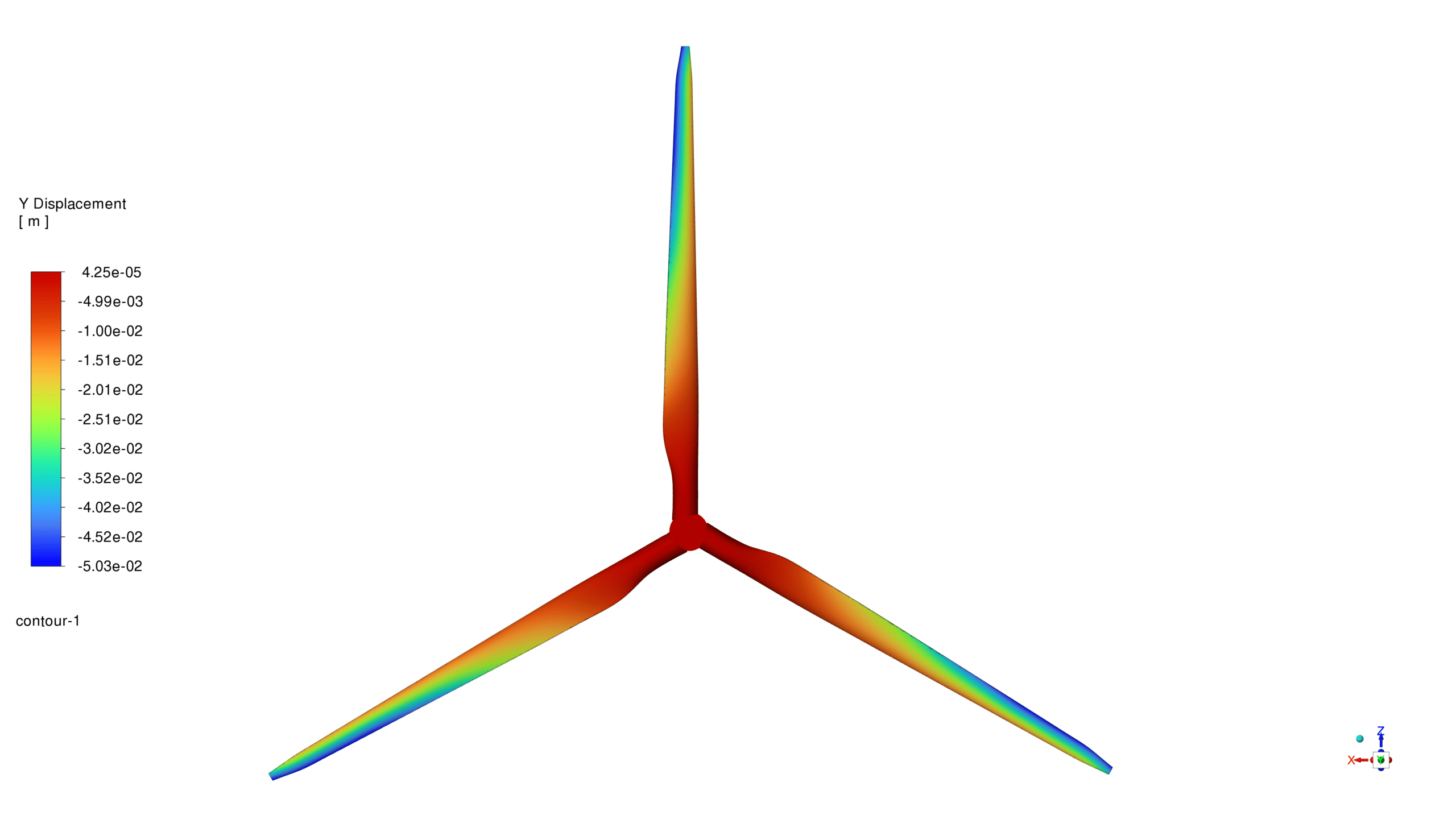
The simulation results show a maximum total deformation of 0.0503 m at the blade tips. This significant deformation highlights the importance of considering structural flexibility in wind turbine design.
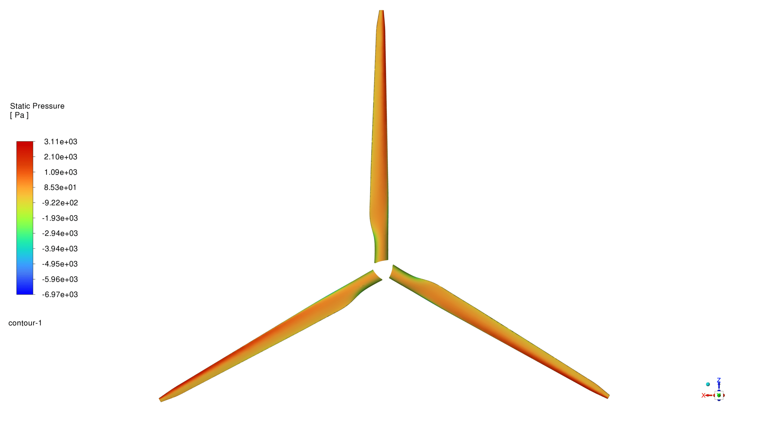
The static pressure contour reveals a pressure difference between the upper and lower surfaces of the blades, ranging from -6970 Pa to 3110 Pa. This pressure differential is crucial for generating lift and driving the turbine rotation.
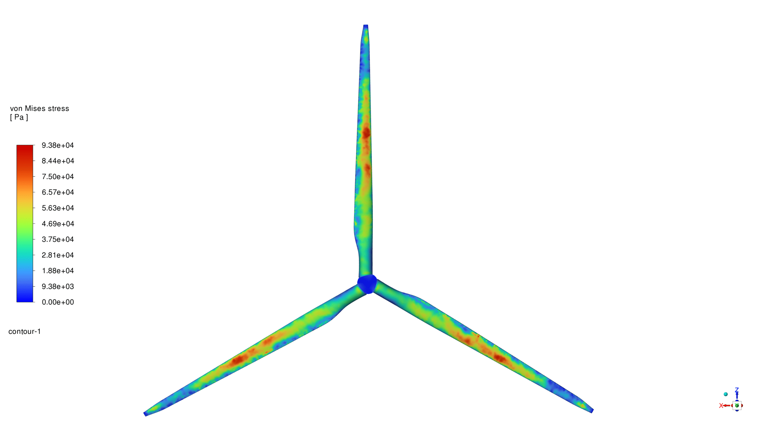
The von Mises stress contour indicates a maximum stress of 9.9878e6 Pa, with high-stress regions similar to those observed in the strain analysis. This information is vital for assessing the structural integrity and fatigue life of the turbine blades.
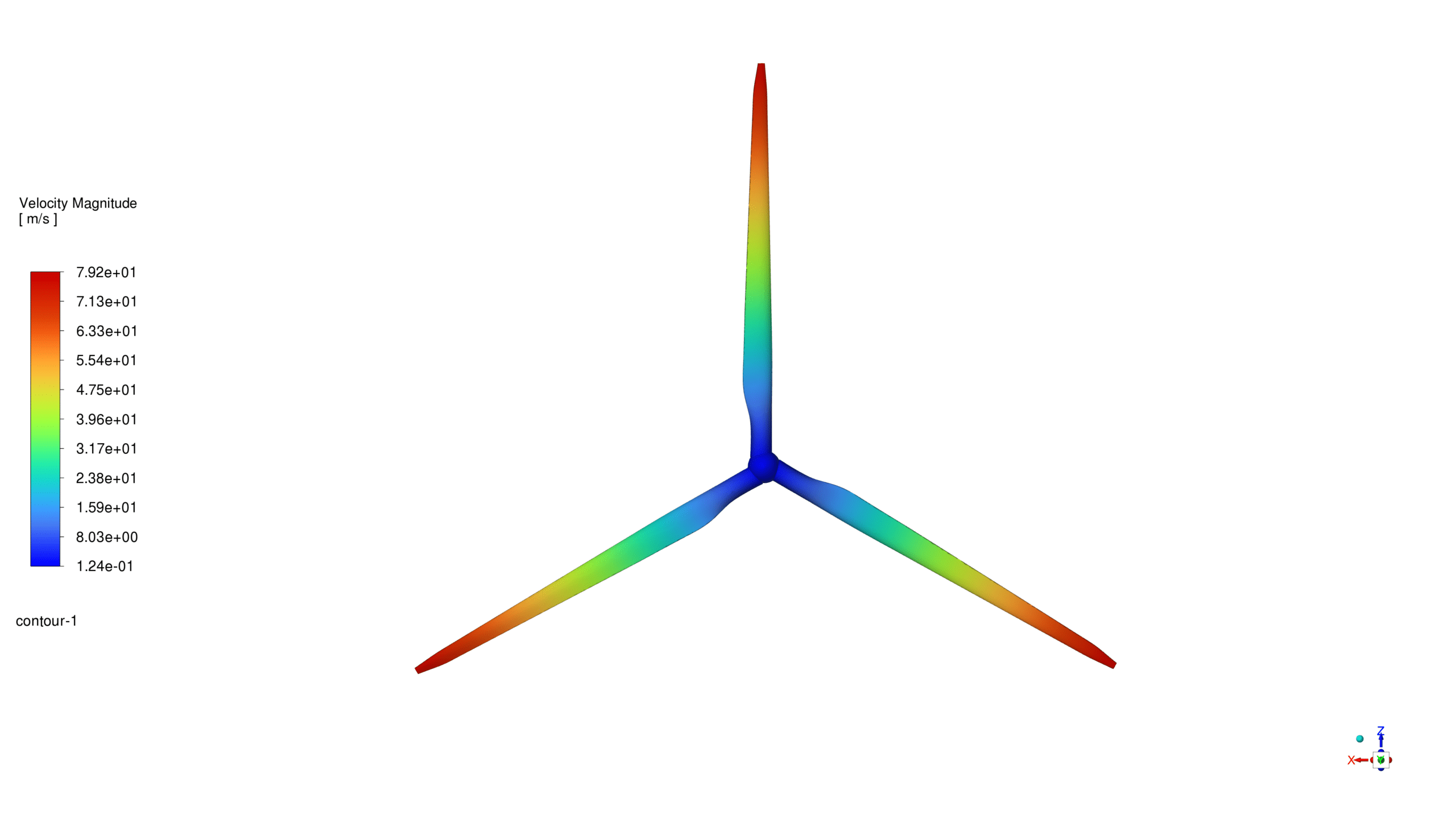
The velocity magnitude contours show a maximum velocity of 79 m/s at the blade tips, with a gradual decrease towards the hub. The wake region behind the turbine is clearly visible, indicating energy extraction from the incoming wind.




Reviews
There are no reviews yet.