Francis Turbine Cavitation, Ansys Fluent CFD Simulation
$200.00 $100.00 Student Discount
To Order Your Project or benefit from a CFD consultation, contact our experts via email (info@mr-cfd.com), online support tab, or WhatsApp at +44 7443 197273.
There are some Free Products to check our service quality.
If you want the training video in another language instead of English, ask it via info@mr-cfd.com after you buy the product.
Description
Multi-phase Flow Analysis of Cavitation Characteristics in Francis Turbine Using Ansys Fluent CFD Simulation
Describtion
The computational fluid dynamics (CFD) analysis of a Francis turbine was conducted using ANSYS Fluent software to investigate its performance characteristics and flow behavior. This study aims to provide detailed insights into the pressure distribution, velocity patterns, and potential cavitation phenomena within the turbine system. The simulation incorporates advanced numerical models and careful consideration of boundary conditions to ensure accurate results.
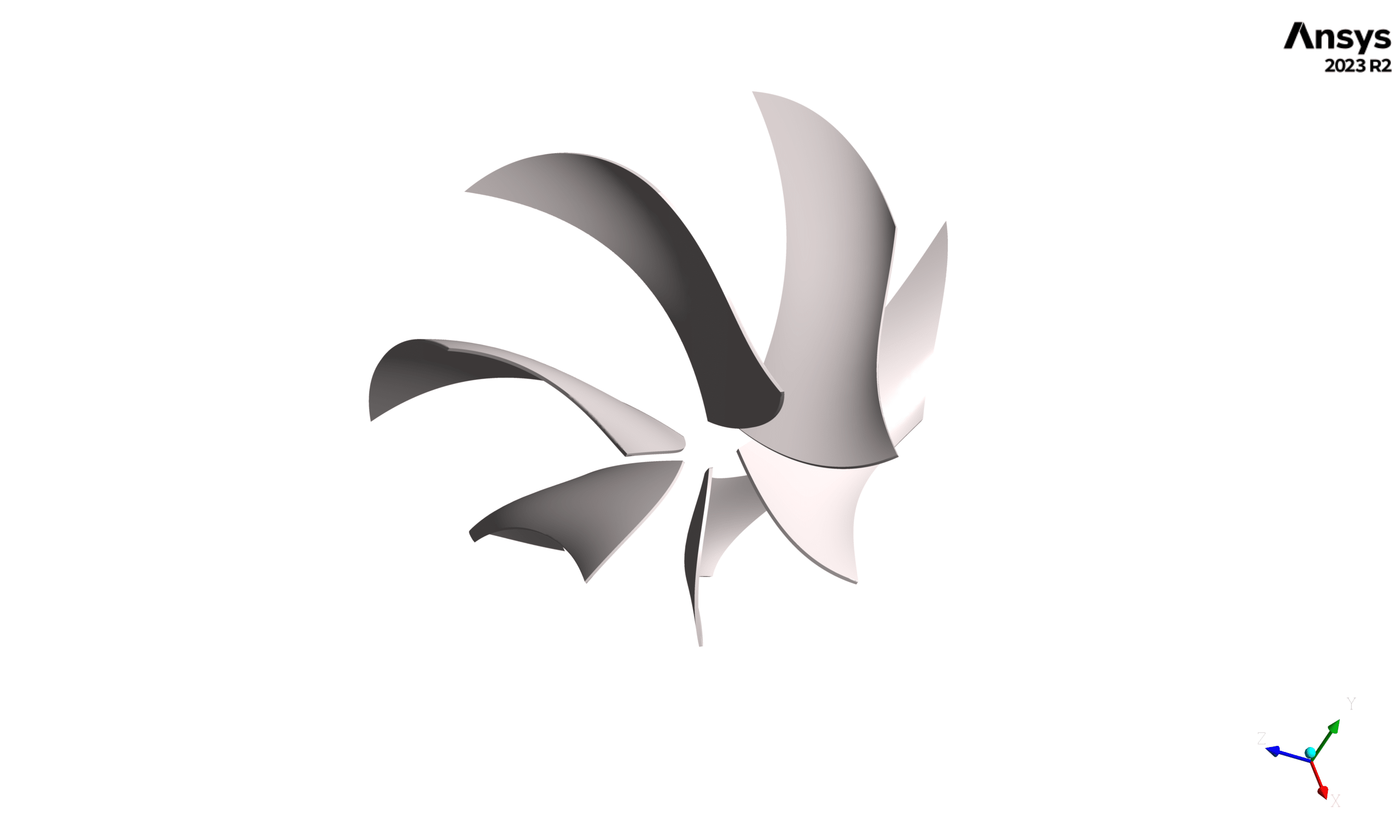
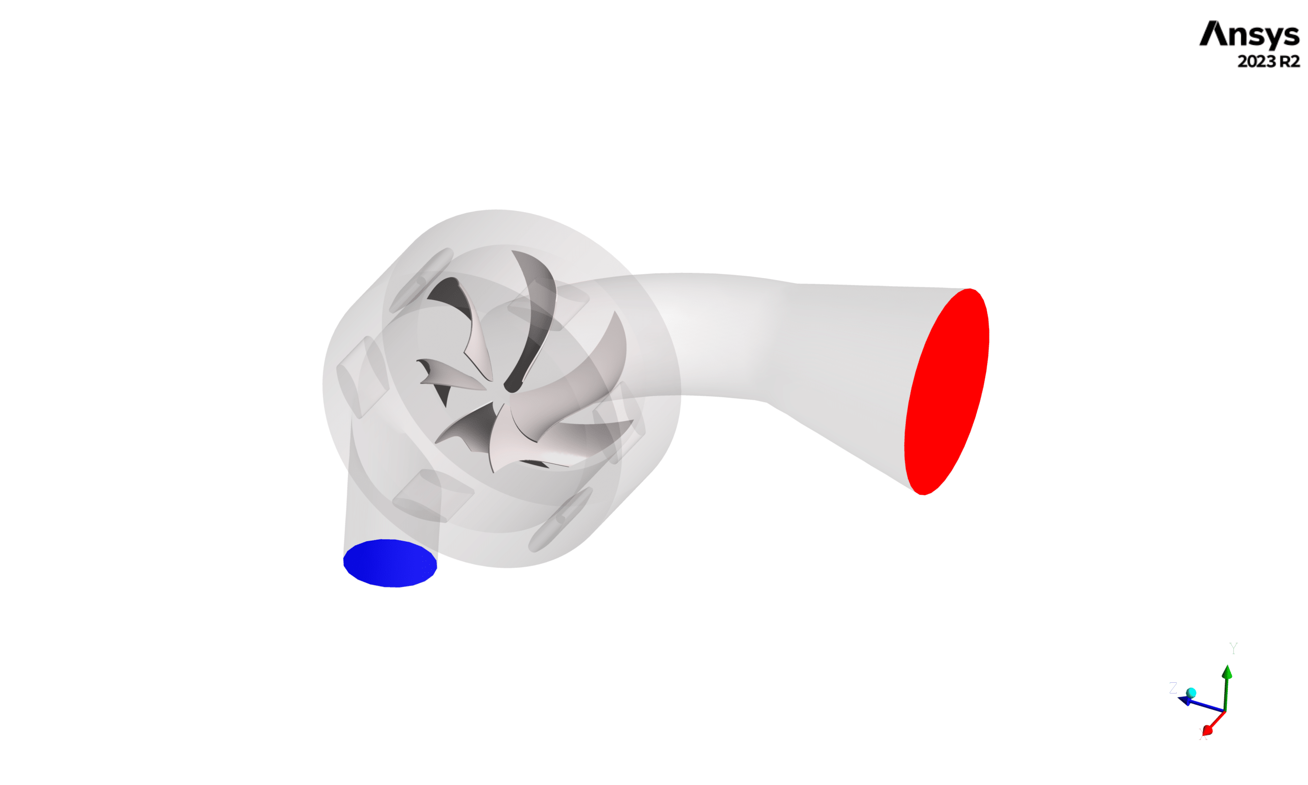
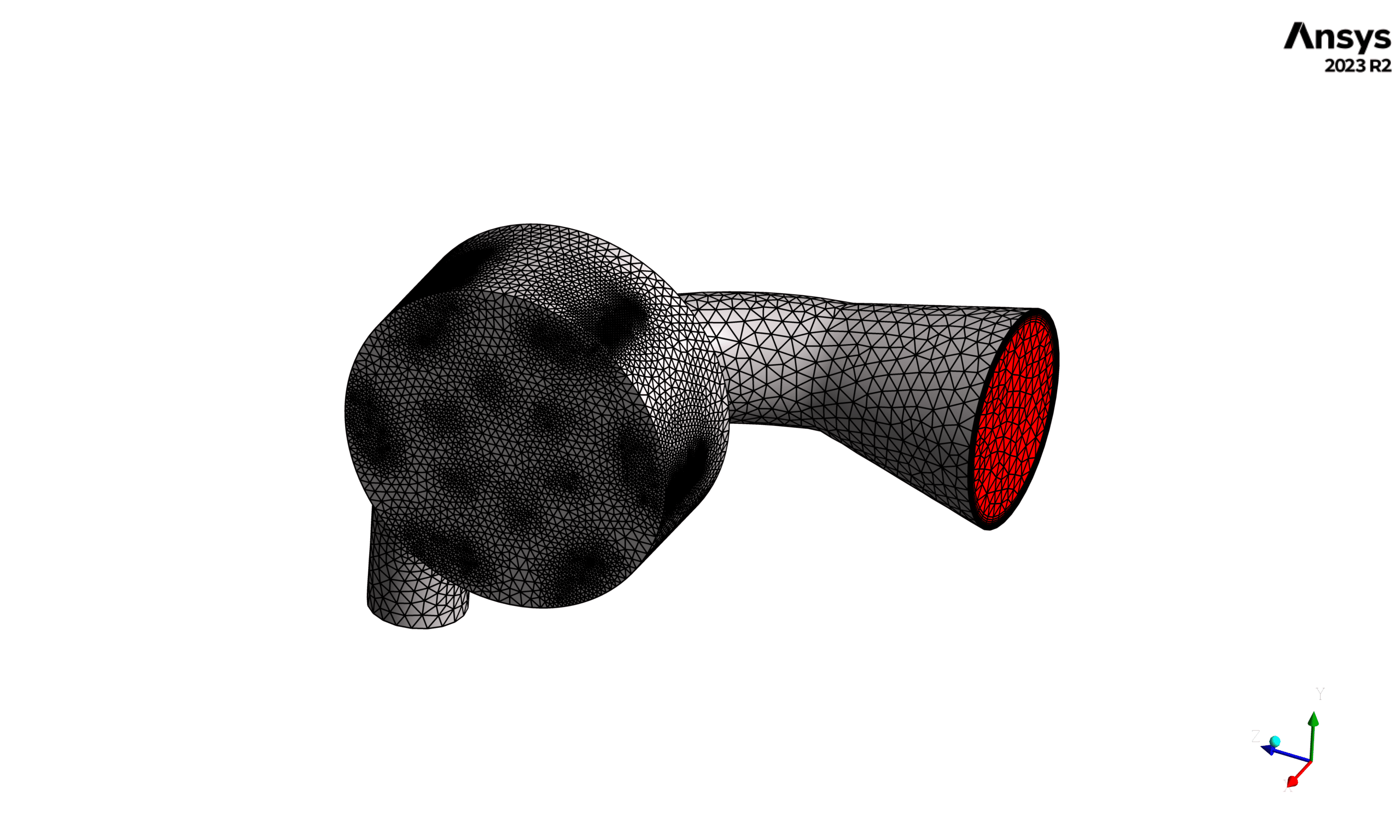
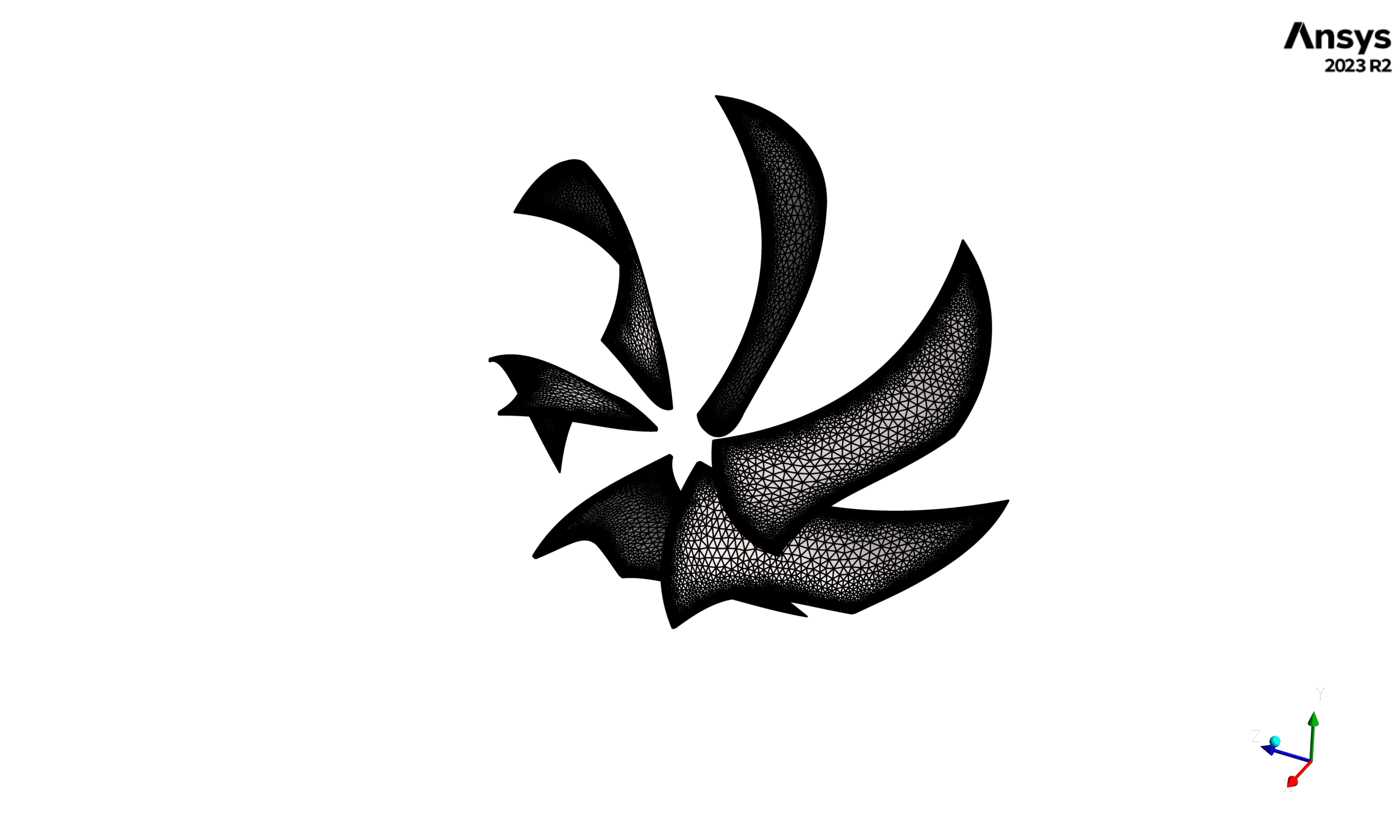
Geometry and Mesh Generation: The initial phase of the project involved creating the turbine geometry using ANSYS Design Modeler. Following the geometry creation, a high-quality computational mesh was generated using ANSYS Meshing. The mesh consists of approximately 5 million tetrahedral cells, carefully refined to capture complex flow features and maintain excellent mesh quality metrics. This detailed mesh resolution was chosen to ensure accurate flow prediction, particularly in critical regions such as the runner blades and draft tube.
Methodology
The simulation employed a pressure-based solver with gravity effects enabled (-9.81 m/s² in Y-direction) to account for buoyancy effects. A Volume of Fluid (VOF) multiphase approach was implemented to model the interaction between water (primary phase) and water vapor (secondary phase). The inclusion of cavitation modeling in the heat and mass transfer settings allows for the prediction of potential cavitation zones. The k-ω SST turbulence model was selected for its superior performance in predicting lift and drag forces, which are crucial for accurate turbine performance assessment.
The rotating components of the turbine were modeled using a frame motion approach with a rotational speed of 200 RPM. The inlet boundary condition was specified as a mass flow inlet with a flow rate of 1.996 kg/s, while a pressure outlet condition was applied at the exit. These boundary conditions were carefully chosen to represent realistic operating conditions of the Francis turbine.
The numerical solution was obtained using a coupled algorithm for pressure-velocity coupling, ensuring robust convergence. Spatial discretization schemes were selected to maintain high accuracy, including PRESTO! for pressure calculations and second-order upwind schemes for both momentum and turbulence quantities. The solution was initialized using standard initialization procedures to establish a stable starting point for the calculations.
Results
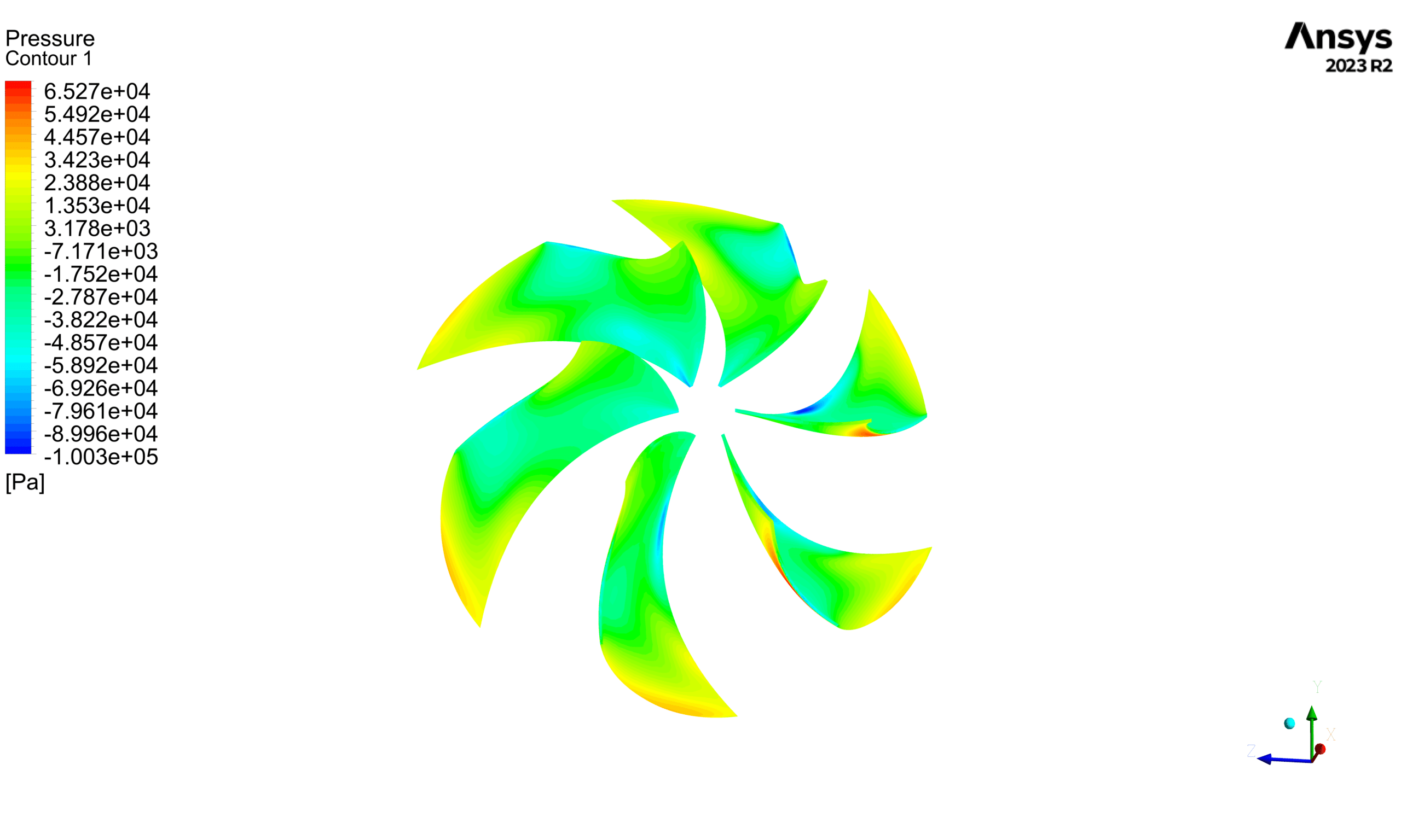
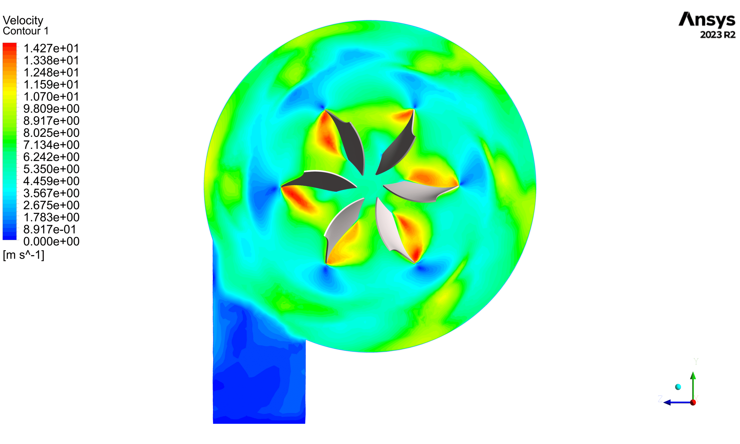
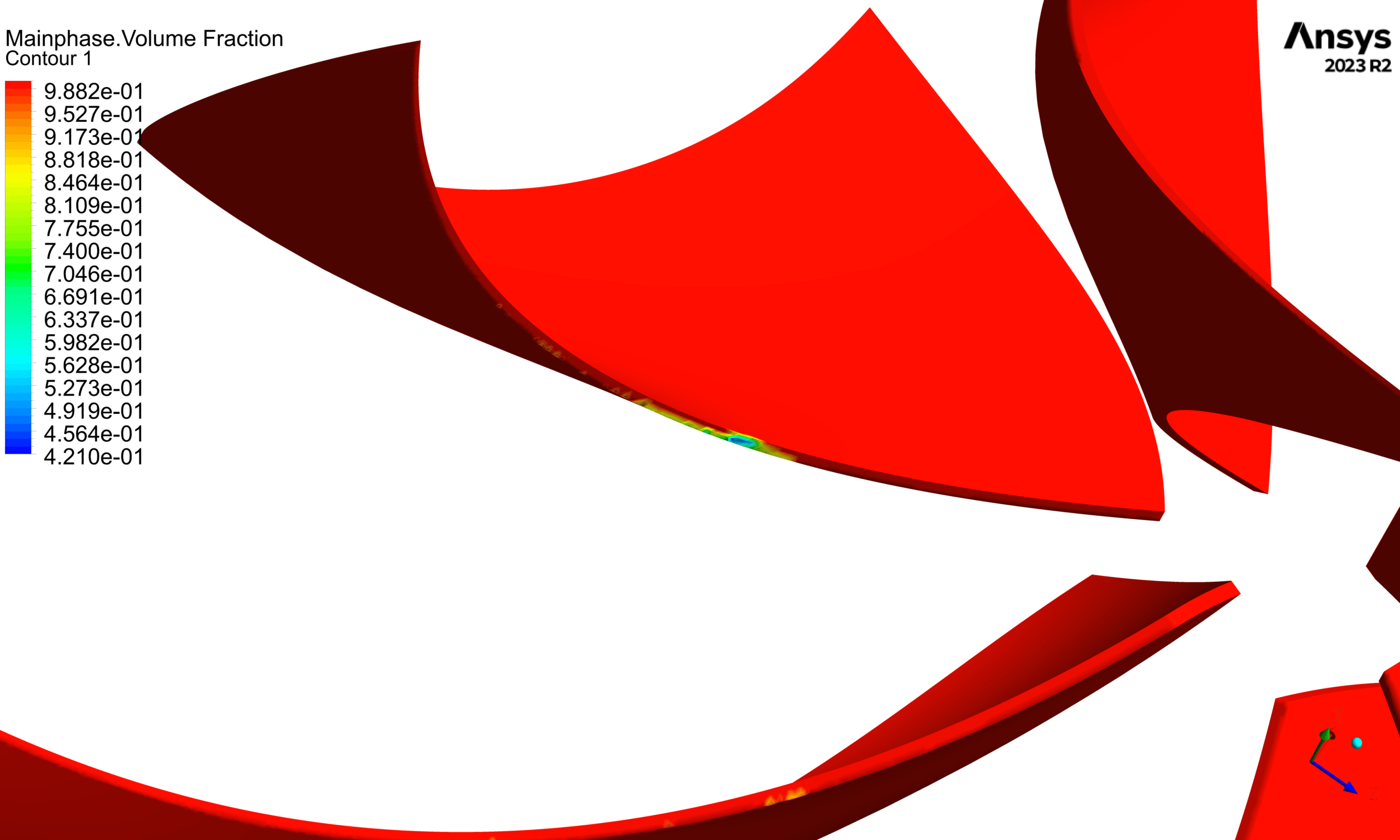
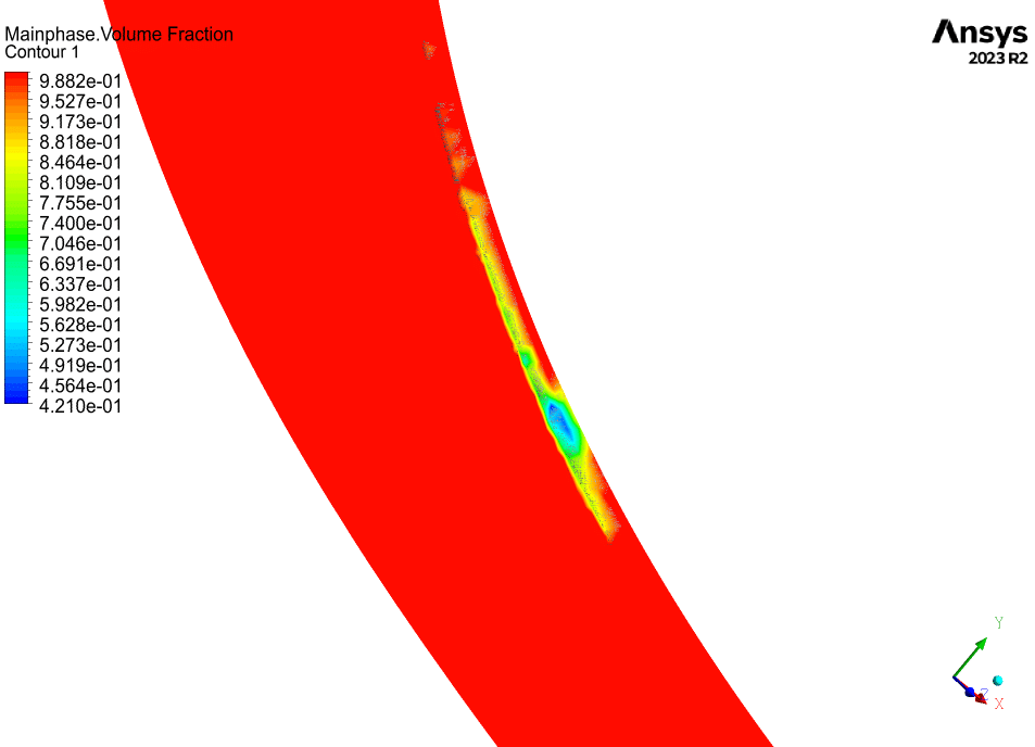
The simulation results provide comprehensive insights into the turbine’s performance characteristics. The pressure contours reveal the pressure distribution throughout the turbine passage, while velocity contours illustrate the flow patterns and potential areas of flow separation. The volume fraction of water distribution helps identify regions where cavitation might occur. These results are crucial for understanding the turbine’s operational behavior and identifying potential areas for design improvement.
Conclusion
The CFD analysis successfully captured the complex flow phenomena within the Francis turbine. The detailed numerical setup and careful consideration of physical models ensure the reliability of the results. This analysis provides valuable insights for understanding the turbine’s performance characteristics and can serve as a basis for future design optimizations.




Reviews
There are no reviews yet.