FSI Method for Water Turbine Vibration CFD Simulation
$270.00 $135.00 Student Discount
The present study investigates the water flow around a vertical water turbine considering unsteady CFD simulation.
Click on Add To Cart and obtain the Geometry file, Mesh file, and a Comprehensive ANSYS Fluent Training Video.To Order Your Project or benefit from a CFD consultation, contact our experts via email (info@mr-cfd.com), online support tab, or WhatsApp at +44 7443 197273.
There are some Free Products to check our service quality.
If you want the training video in another language instead of English, ask it via info@mr-cfd.com after you buy the product.
Description
FSI Method for Water Turbine, ANSYS Fluent CFD Simulation Training
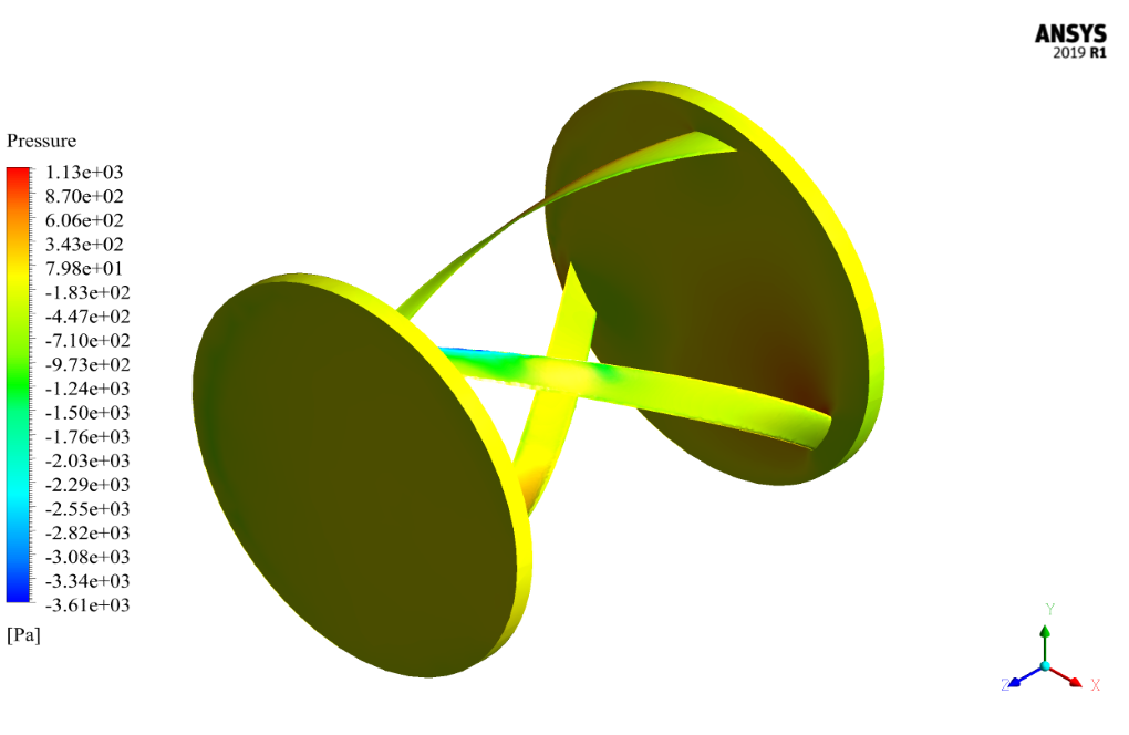
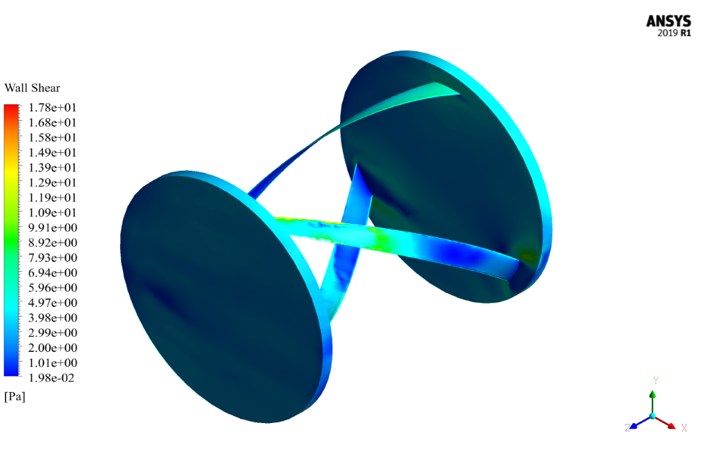
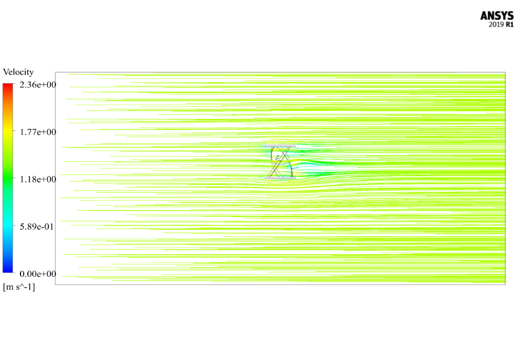
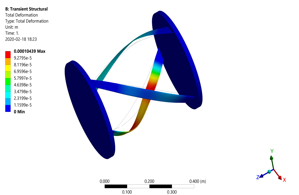
The present study investigates the water flow around a vertical water turbine considering unsteady CFD simulation by ANSYS Fluent software. In the present case, it is assumed that the turbine blades are affected by the flow of the passing fluid; that is, the fluid flowing through the turbine blades impedes forces on the turbine body and these forces cause deformation or resizing of the body of these blades. Therefore, the present problem consists of two fluid and solid solutions at the same time and hence, the FSI method and the coupling between the fluid flow and the Transient Structural are used.
Assumptions for Water Turbine CFD Simulation using FSI Method
Simulation is Transient and the solver is pressure-Based. Also, the gravity force effect is ignored.
Geometry & Mesh of the Water Turbine
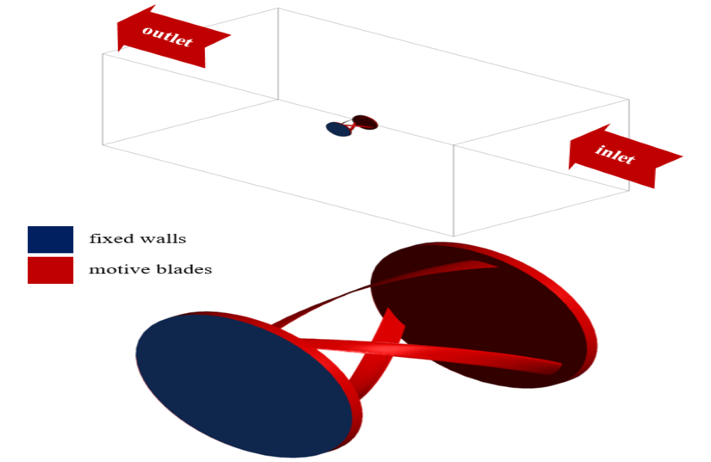
The present 3-D model was designed by Design Modeler software. The geometry of the model consists of a large cubic space as a fluid domain and the water turbine inside this space as a solid domain. The unstructured mesh was carried out by ANSYS Meshing software. The element number is 523202.
CFD Simulation
Here is a summary of the steps to define and solve the problem in the table:
| Models | |||
| k-epsilon | Viscous model | ||
| standard | k-epsilon model | ||
| standard wall function | near wall treatment | ||
| Dynamic mesh | |||
| smoothing and remeshing | mesh methods | ||
| system coupling | dynamic mesh zone | ||
| Boundary conditions for FSI CFD simulation | |||
| velocity-inlet | Inlet | ||
| 1.5 m.s-1 | velocity magnitude | ||
| pressure-outlet | Outlet | ||
| 0 Pa | gauge pressure | ||
| wall | Walls type | ||
| stationary walls | blades and fixed walls | ||
| Solution Methods for FSI Simulation | |||
| Simple | Pressure-velocity coupling | ||
| second-order upwind | pressure | Spatial discretization | |
| second-order upwind | momentum | ||
| first-order upwind | turbulent kinetic energy | ||
| first-order upwind | turbulent dissipation rate | ||
| Initialization (FSI) | |||
| Standard | Initialization method | ||
| 1.5 m.s-1 | x-velocity | ||





Brian Fay MD –
The article I was going through with this tutorial was excellent and complete.
Violet Haley I –
Could you please tell me the role of FSI in water turbine simulation?
MR CFD Support –
Fluid-Structure Interaction (FSI) plays a crucial role in water turbine simulations. It helps to analyze the interaction between the fluid flow and the turbine blades, which is essential for predicting the performance and structural integrity of the turbine.
Laila Strosin I –
How does this simulation handle the rotating motion of the turbine blades?
MR CFD Support –
The simulation uses the sliding mesh technique to handle the rotating motion of the turbine blades. This method allows for accurate modeling of the interaction between the rotating blades and the stationary parts of the turbine.
Kariane Frami –
Can this simulation be used to predict the efficiency of the water turbine?
MR CFD Support –
Yes, the simulation can provide valuable insights into the flow behavior and pressure distribution, which can be used to calculate the efficiency of the water turbine.
Lexus Langworth –
The water turbine simulation seems complex. Could you clarify whether the CFD model accounts for transient blade row interactions, such as the interactions between stationary and rotating components?
MR CFD Support –
In this particular simulation, the focus is on the fluid-structure interaction (FSI) effects where the fluid flowing past the turbine blades imparts forces on the turbine body, leading to deformation or resizing. Standard interaction models between stationary and rotating components, such as the transient blade row interaction models, are not explicitly mentioned in the summary. However, dynamic mesh techniques are employed to handle the motion and deformation, suggesting that there may be an accounting for interactions that involve moving components.
Diamond King –
How accurately can the transient structural software predict blade deformation during operation in this simulation?
MR CFD Support –
In the simulation using FSI for the water turbine, the transient structural software predicts blade deformations based on the forces exerted by the water flow. The software uses advanced algorithms to solve for deformation, coupling the fluid dynamics effects from ANSYS Fluent with the structural response from Transient Structural through system coupling. The accuracy of prediction can be quite high, depending on mesh quality, fluid-structure interaction modeling, and proper definition of the material properties.
Francesca Langworth –
Does the CFD simulation of the water turbine take into account the possibility of cavitation due to the pressure changes around the blades?
MR CFD Support –
Cavitation in the fluid flow around turbine blades is an important factor to consider. However, the training product does not mention the simulation of cavitation effects explicitly. Cavitation modeling would typically require additional settings and assumptions in the simulation setup, such as the use of a cavitation model in conjunction with the viscous and turbulence models.
Blair Ryan PhD –
I’ve read about the use of k-epsilon model and system coupling for the FSI CFD simulation. Could you please explain why this specific viscous model was chosen for the water turbine analysis and how the system coupling impacts the analysis results?
MR CFD Support –
The k-epsilon viscous model is chosen for the water turbine FSI CFD simulation due to its ability to accurately predict the average flow characteristics in turbulent flow conditions, which are common in the environment around a turbine. Its robustness and reliability make it a common choice for industrial applications, including simulation of flow around turbine blades. Regarding the system coupling, it is essential to accurately predict the interaction between the fluid and the structure. The system coupling enables the simulation to capture the effect of the fluid forces on the turbine blades which leads to blade deformation. This deformation in return affects the fluid flow, and only through system coupling can both phenomena be simultaneously calculated for a realistic and dynamic simulation.
Andreane Huels Jr. –
Hello
His training was excellent.
Prof. Reginald O’Keefe PhD –
This training module sounds really comprehensive. I’m especially impressed with how the dynamic mesh and system coupling are articulated!
MR CFD Support –
Thank you for recognizing our efforts. It’s great to hear that our training material is clear and beneficial for understanding complex subjects such as dynamic mesh and system coupling.
Agustin Runolfsdottir II –
I am in awe of how detailed the water turbine FSI simulation is! It is impressive how the coupling of fluid flow and structural dynamics can predict turbine blade deformations so accurately. The integration of the dynamic mesh technique for the constantly reshaping geometry is also fascinating!
MR CFD Support –
Thank you for your review and appreciation of the FSI simulation for the water turbine in ANSYS Fluent. We are thrilled to hear that you found the detailed approach and the dynamic mesh technique helpful and accurate for predicting structural deformations in response to fluid flow forces. It’s always our goal to deliver high-quality, comprehensive learning materials!
Sandra Grant IV –
I was wondering whether you can clarify how the transient nature of the simulation affects the results, particularly in terms of the forces affecting the turbine blades and subsequent deformations.
MR CFD Support –
The transient nature of the simulation allows for the capture of time-dependent behaviors, such as unsteady flow patterns around the turbine blades that result in dynamic forces. These forces have a direct impact on the deformation of the turbine blades. As the simulation progresses, these forces are calculated at each time step, interacting with the structure’s material properties, leading to real-time calculations of deformation and allowing for analysis of the turbine’s response to the cyclic loading over time.
Dr. Pietro Kub IV –
Are the turbine blade materials considered in the vibration analysis during the FSI simulation, and if so, what type of materials are used?
MR CFD Support –
In the FSI simulation, the materials for the turbine blades must indeed be considered to accurately predict their deformation and vibrational characteristics. Generally, the material properties such as density, Young’s modulus, Poisson’s ratio, and damping factor would be specified. However, the review doesn’t include the type of material used. In practice, materials commonly used for turbine blades, like aluminum or steel alloys, would be characterized and included in the analysis.
Cecilia Romaguera –
I really enjoyed learning about the FSI method for water turbine vibration through your CFD simulation product. It’s insightful how the interactions between the fluid flow and the turbine blades are taken into account to determine the structural responses. The details on the boundary conditions, models, and solution methods provided are thorough and help understand the intricacies of such simulations. Thank you for a comprehensive training module!
MR CFD Support –
Thank you for your positive feedback! We’re thrilled to hear that you found the training module on the FSI method for water turbine vibration simulation comprehensive and educational. Our goal is to provide in-depth knowledge and understanding of CFD simulations to our customers. We appreciate your comments and are glad you enjoyed learning from our product.
Dayne Lindgren –
Your CFD training material on the FSI method for water turbine vibration simulation has shed new light on fluid-structure interactions. Through a mix of three-dimensional modeling and boundary condition exploration, I found myself becoming more proficient each step of the way. Brilliant work, take my genuine appreciation!
MR CFD Support –
Thank you very much for your positive feedback! We’re overjoyed to hear that our training material on water turbine vibration simulation using the FSI method was instrumental to your understanding of fluid-structure interactions. We strive to provide comprehensive learning resources and your appreciation truly motivates us. If you have any more questions or need further assistance in your learning journey, please let us know. Happy simulating!
Ismael Wisoky Sr. –
The CFD Simulation Training for the water turbine sounds quite comprehensive. I’m really impressed by how deformation is incorporated into the analysis with FSI. What post-processing is done to display the results of the fluid interaction with the water turbine blades?
MR CFD Support –
In post-processing, the analysis would typically involve the visualization of flow patterns around the turbine blades with streamlines and contour plots. The deformation and displacement of the blades due to fluid interaction would be displayed through stress and strain distribution plots, and possibly animation to show the changes over time during the simulation.
April Beatty –
What role does the standard k-epsilon model play in this simulation, and how does it differ from other turbulence models?
MR CFD Support –
The standard k-epsilon model is a two-equation turbulence model used in the CFD simulation for predicting the characteristics of the turbulent fluid flow. It accounts for the turbulent kinetic energy (k) and its dissipation rate (epsilon). This model is widely used for its robustness and relatively simple implementation compared to more complex turbulence models. Its role in this simulation is to provide a more accurate estimation of the flow’s turbulence around the turbine blades, which is important for calculating the forces exerted by the fluid on the blades in an FSI analysis. Other turbulence models may offer more precision in certain specific applications but can be more computationally intensive or require finer mesh resolution.
Dr. Stephen Zemlak Jr. –
After running my simulation following the MR CFD guidance for the water turbine, it feels like I’ve got a grip on FSI concepts. Definitely helped to bridge the gap between theory and application. No question, just a big thanks!
MR CFD Support –
Thank you so much for your kind words! We’re delighted to hear that our product was helpful in advancing your understanding of FSI concepts and practical simulation work. If you need any more help or further learning tools, please don’t hesitate to reach out. Your success is what motivates us to keep creating high-quality learning materials!
Dr. Jacquelyn Mitchell IV –
The results of the FSI analysis on the water turbine, especially regarding the blade deformation, would be fascinating to see. Are there any animations or visual presentations available that detail the dynamic interactions and deformations?
MR CFD Support –
Yes, the analysis of the water turbine using FSI incorporates visual outputs, such as animations, to show the dynamic interactions and blade deformations. These allow you to observe the extent of deformation due to the fluid forces, showcasing the application’s realism of FSI in simulating complex interactions between fluid and structure.
Rosina Medhurst –
I found the training helpful, but is static pressure-adjustment used in cases where the FSI interaction heavily modifies the flow field around the turbine?
MR CFD Support –
Static pressure adjustment is typically implemented when pressures vary significantly due to interactions and changes in the domain. In the FSI simulation case, pressure adjustments are part of the solver iterations and coupling mechanism to ensure accurate pressure fields that consider the deformations and resizing of the blades.
Judd Rogahn –
I’m really curious, how did the interaction between the water flow and the turbine blade dynamics influence the overall performance and efficiency of the water turbine in this simulation?
MR CFD Support –
In the FSI simulation, the interaction between the water flow and the turbine blade dynamics results in fluid forces that impact the blades, leading to deformations. These deformations and the resultant blade movements in turn modify the flow field around the blades. The coupling of these effects can have significant impacts on the turbine’s performance and efficiency. Accurate capture of these interactions often leads to better predictions of the turbine’s operational behavior, providing insights into stress distribution, potential fatigue life, and optimum operating conditions for maximal efficiency.
Autumn Huels –
Can you detail the specific mesh adaptivity techniques used for handling the dynamic aspects of blade deformation during the simulation?
MR CFD Support –
In this CFD simulation with FSI, dynamic mesh techniques such as smoothing and remeshing were applied to handle blade deformation. Smoothing adjusts the mesh to maintain quality without changing topology. Remeshing creates new cells and adjusts the existing mesh when large deformations occur, thus keeping a high-quality mesh that properly adapts to the changing geometry of the deforming turbine blades.
Dan Lowe MD –
I am fascinated with the way the water turbine interacts with the fluid forces. Can the deformation or resizing results from the study be weighed against the real-world performance statistics of a similar water turbine?
MR CFD Support –
Thank you for your interest in the interaction of the water turbine with fluid forces. Yes, the simulation accounts for the deformation or resizing of the turbine blades due to fluid forces, which can be compared with real-world performance statistics to evaluate the accuracy of the simulation model. Computational results can be validated by experimental or field data to ensure the model’s predictive capabilities reflect actual turbine performance under similar operating conditions.