Gas Turbine Intake CFD Analysis
$40.00 $20.00 Student Discount
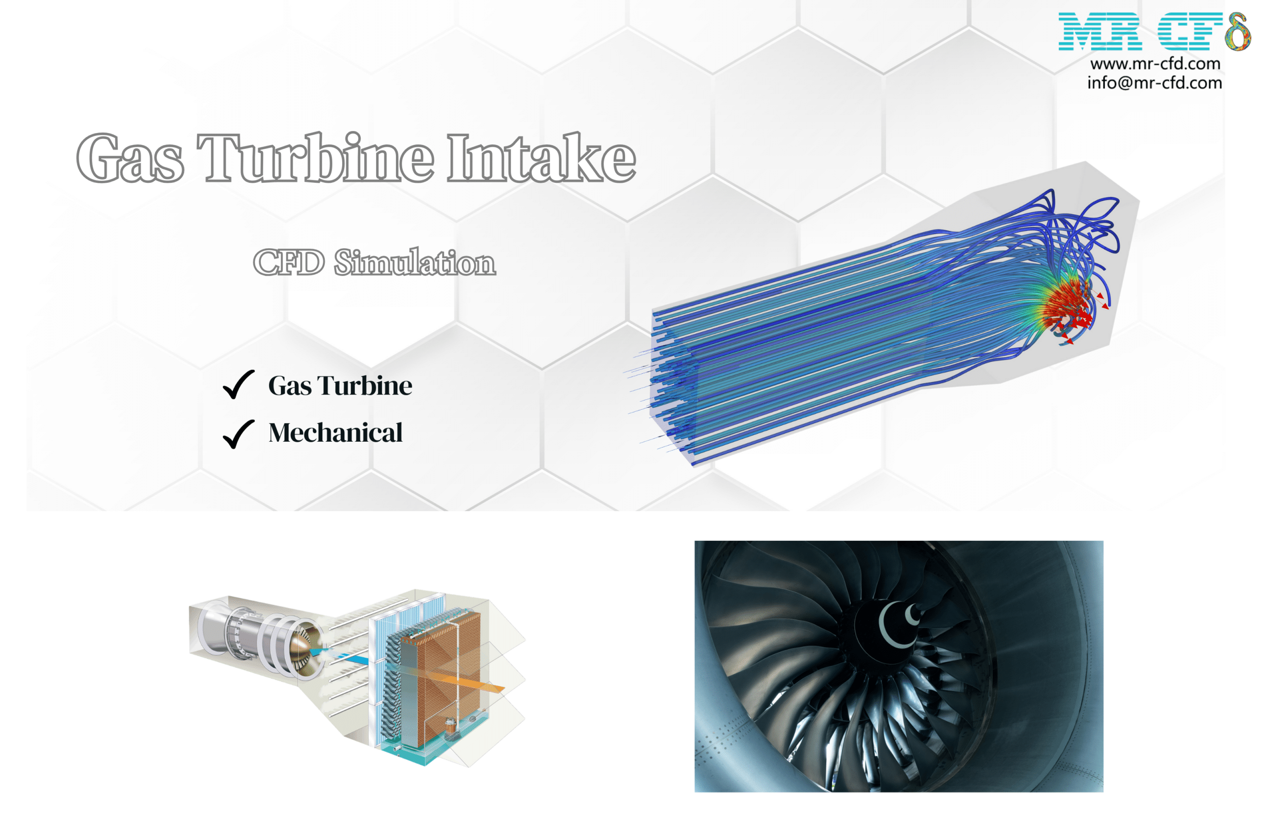
- This report presents a comprehensive CFD analysis of a Gas Turbine Intake using ANSYS Fluent.
- The study investigates flow behavior and pressure characteristics within a complex intake geometry, utilizing a structured mesh of 1,494,720 elements.
- The simulation employs a pressure-based, steady-state solver with the Realizable k-epsilon turbulence model.
- Key results include velocity magnitude contours, pressure distribution, and turbulence kinetic energy patterns throughout the intake system.
- An area-weighted average pressure of 320.84187 Pa at the inlet offers quantitative data on entrance conditions.
To Order Your Project or benefit from a CFD consultation, contact our experts via email (info@mr-cfd.com), online support tab, or WhatsApp at +44 7443 197273.
There are some Free Products to check our service quality.
If you want the training video in another language instead of English, ask it via info@mr-cfd.com after you buy the product.
Description
Gas Turbine Intake CFD Analysis, ANSYS Fluent Tutorial
Introduction
This report presents a detailed Computational Fluid Dynamics (CFD) analysis of a Gas Turbine Intake using ANSYS Fluent. The study aims to investigate the flow behaviour and pressure characteristics within the intake geometry, providing valuable insights into the performance and efficiency of this critical component of a gas turbine system.
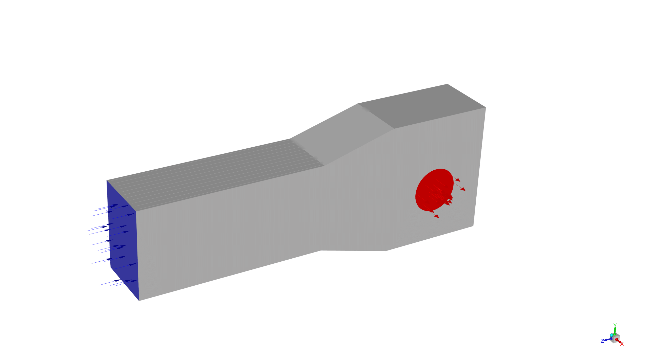
The simulation geometry, designed using ANSYS Design Modeler, represents a complex intake structure with multiple bends and varying cross-sections. The domain includes an inlet at one end and an outlet at the other, allowing for the investigation of airflow through the entire intake system. The geometry is optimized to capture the flow dynamics, pressure variations, and potential turbulence within the intake.
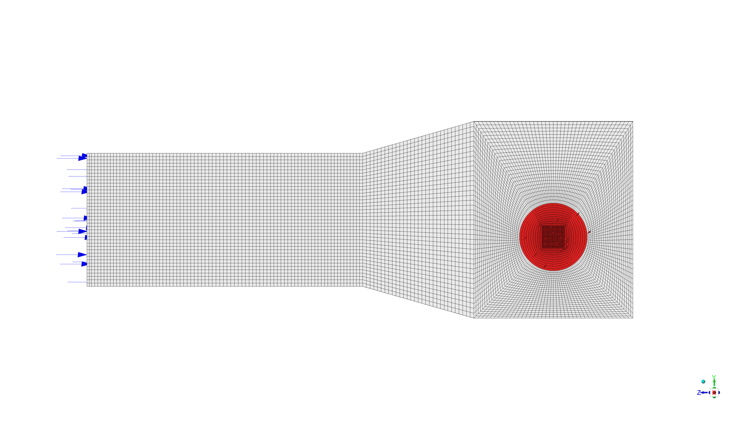
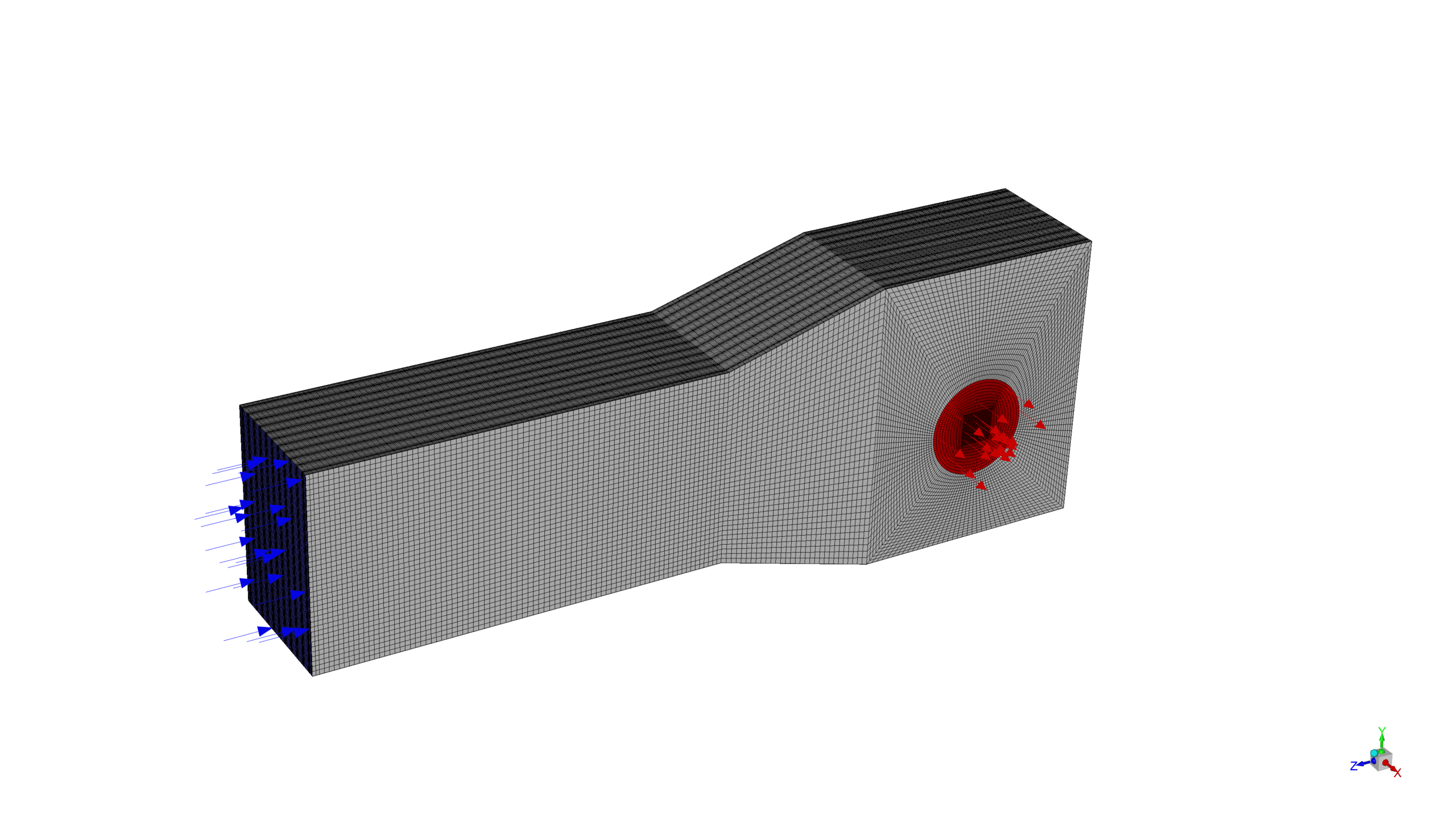
ANSYS Meshing was employed to generate a high-quality structured mesh comprising 1,494,720 elements. This mesh density provides sufficient resolution to accurately capture the flow dynamics, turbulence effects, and pressure variations within the domain. The structured nature of the mesh ensures efficient computation and helps in resolving the complex flow patterns expected in the gas turbine intake.
Methodology
A pressure-based, steady-state solver was employed to capture the flow characteristics of the gas turbine intake.
The Realizable k-epsilon turbulence model with standard wall function was chosen to accurately represent the turbulent nature of the flow, especially in regions with complex geometry and potential flow separation.
A surface report was generated to calculate the area-weighted average pressure at the inlet, which was found to be 320.84187 Pa.
Results
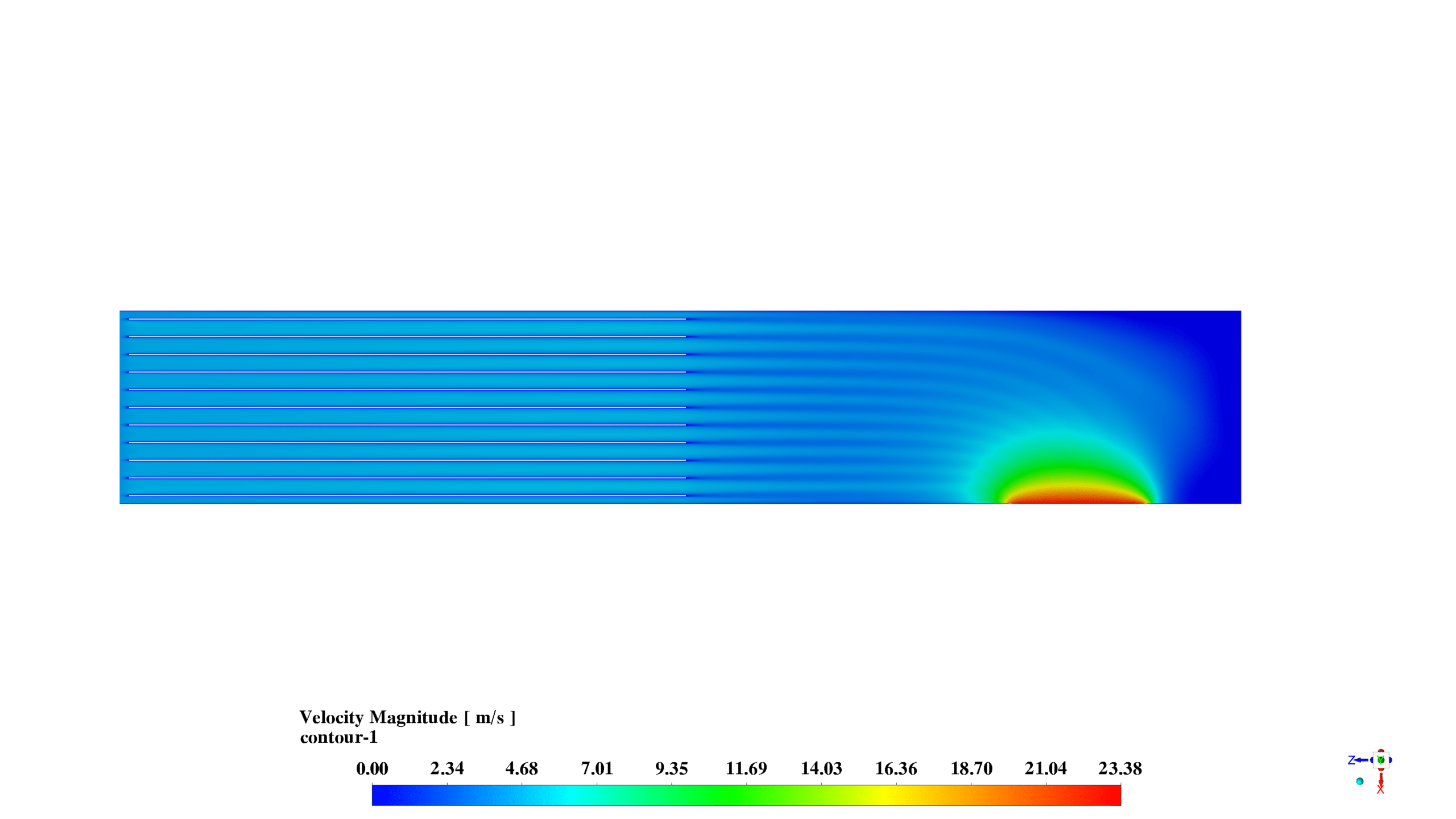
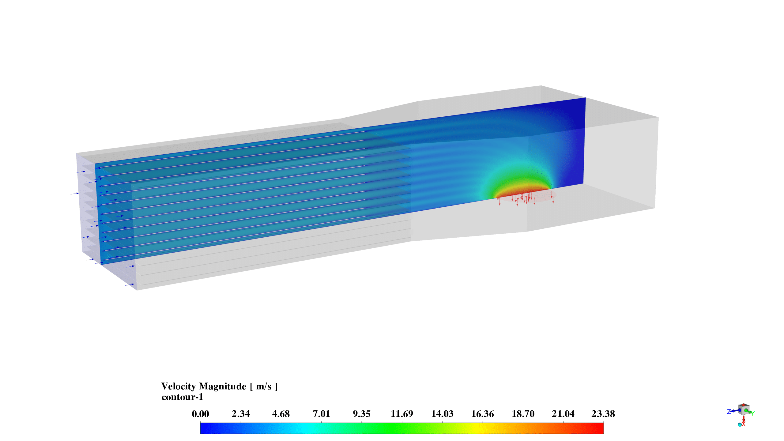
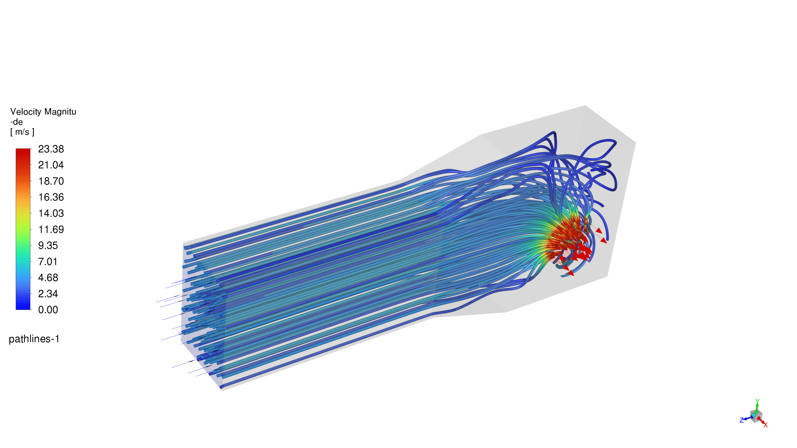
The velocity magnitude contours reveal the distribution of air velocity throughout the intake. Lower velocities are observed near the walls and in regions with larger cross-sections, while higher velocities are seen in areas where the flow is constricted or redirected.
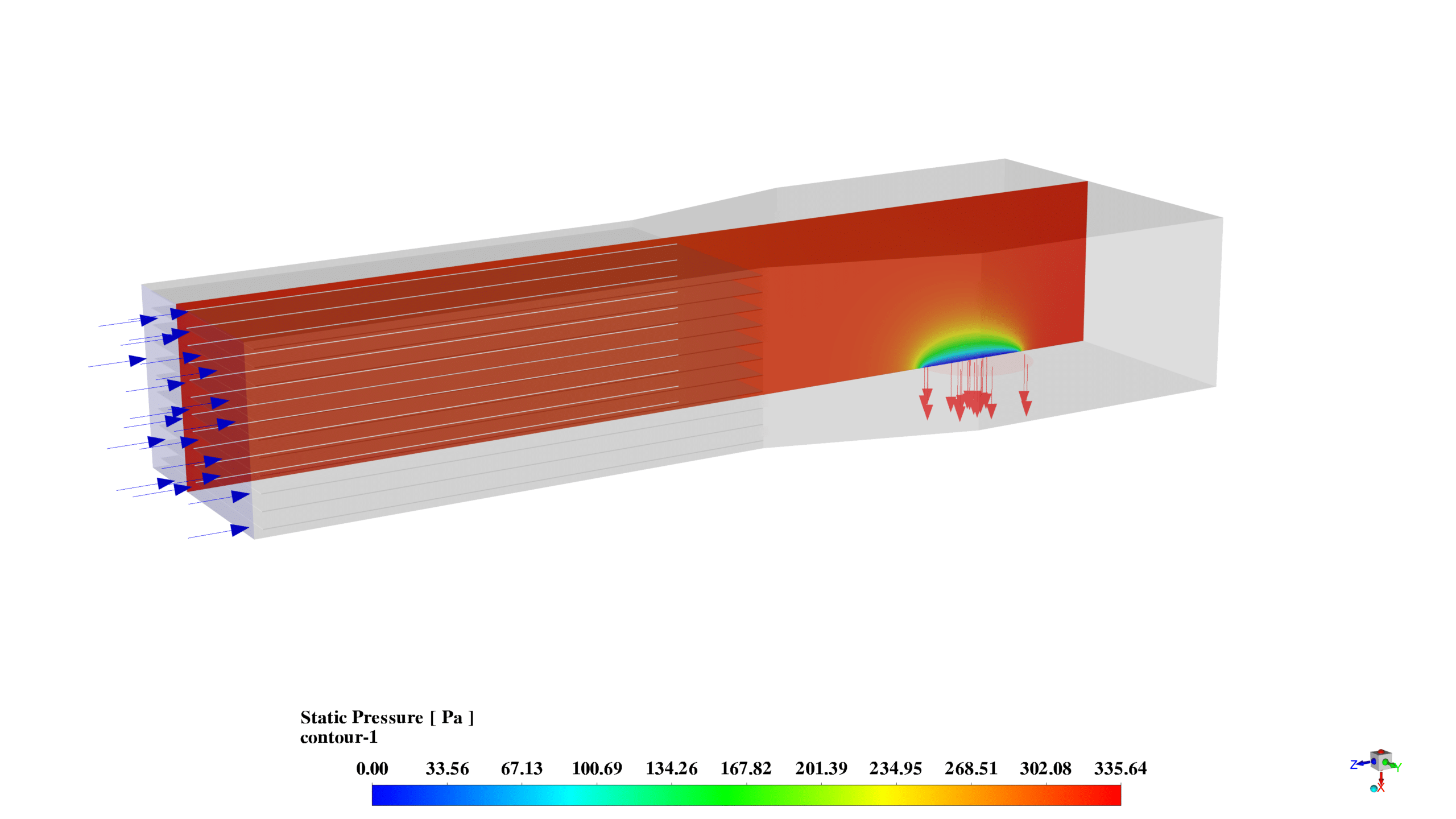
The pressure contours demonstrate the pressure distribution within the intake system. A higher pressure region is observed at the inlet, with pressure gradually decreasing as the flow progresses through the intake. This pressure variation is crucial for understanding the intake’s performance and its impact on the overall gas turbine efficiency.
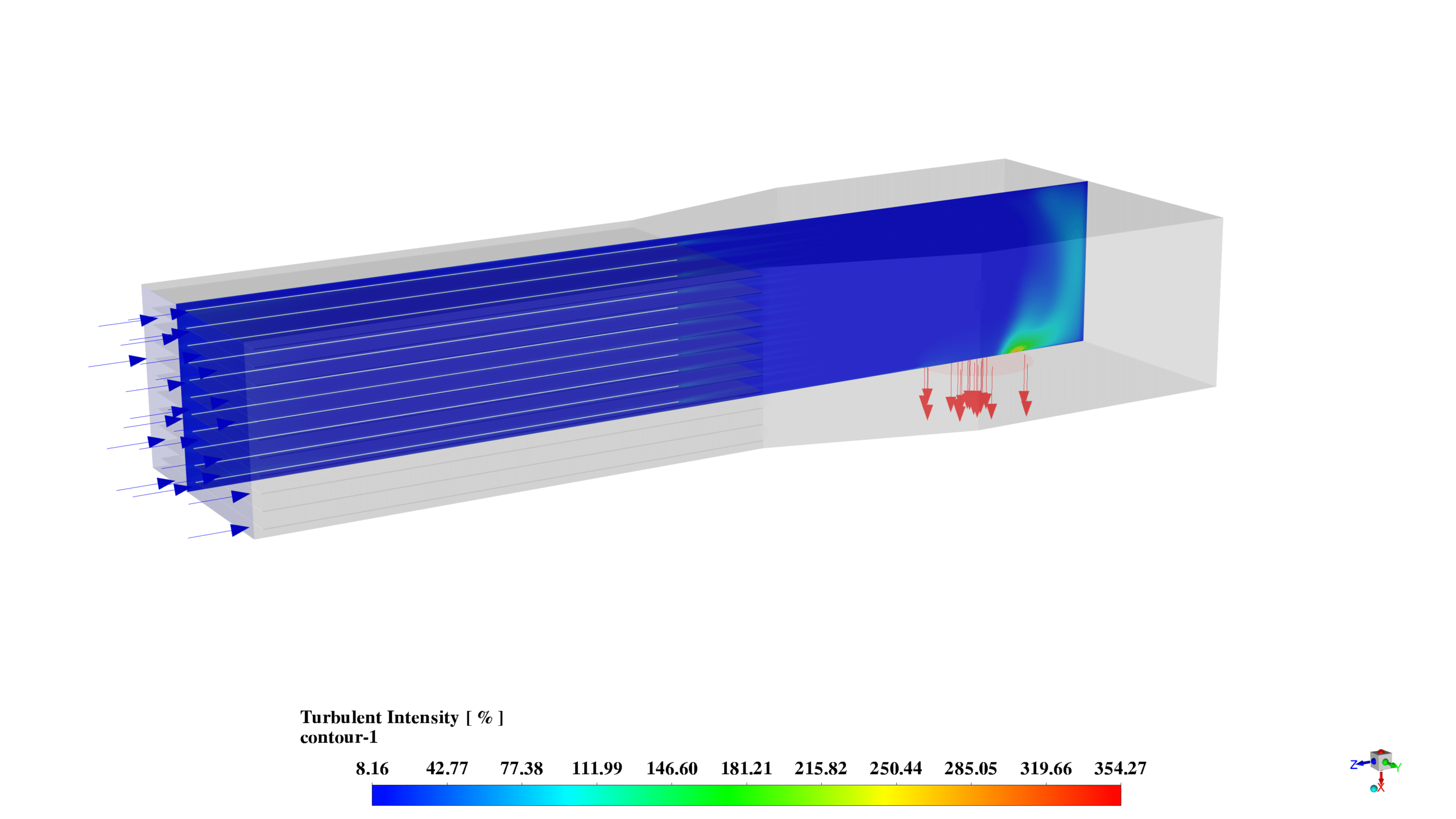
The turbulence kinetic energy contours illustrate the regions of high turbulence within the intake. Higher turbulence is evident in areas where the flow changes direction abruptly or passes through constrictions, which is important for identifying potential areas of energy loss or flow instability.
The simulation captures the essential flow characteristics of the gas turbine intake, with clear indications of velocity changes and pressure variations throughout the geometry.
The pressure distribution aligns with expectations for a complex intake system, with a gradual pressure drop from inlet to outlet.
The velocity profile shows acceleration in constricted areas and deceleration in expanded regions, which is typical for intake systems.
The area-weighted average pressure at the inlet (320.84187 Pa) provides a quantitative insight into the pressure conditions at the entrance of the intake system.
The turbulence kinetic energy distribution helps identify potential areas of concern where flow separation or excessive turbulence might occur, which could impact the intake’s performance.



Reviews
There are no reviews yet.