Gasification in Gasifier Chamber, P1 Radiation Model
$240.00 $120.00 Student Discount
- The present problem simulates the gasification process inside a gasifier chamber by ANSYS Fluent.
- The present 3-D model is designed using Design Modeler software. The meshing of the model has been done using ANSYS Meshing software. The element number is 219170.
- Water vapor is created by the process of evaporation of water droplets inside the chamber by applying DPM.
- The species transport model with volumetric reactions has been used and to define the type of reactants and the process of chemical reactions. The CHEMKIN mechanism has been used, which includes 5 chemical reactions involving 8 different types of reactants and products.
- This model also assumes that Radiation heat transfer due to chemical reactions occurs inside the gasifier chamber, and hence, the P1 model is defined for simulation.
To Order Your Project or benefit from a CFD consultation, contact our experts via email (info@mr-cfd.com), online support tab, or WhatsApp at +44 7443 197273.
There are some Free Products to check our service quality.
If you want the training video in another language instead of English, ask it via info@mr-cfd.com after you buy the product.
Description
Gasification Project Description
The present problem simulates the gasification process inside a gasifier chamber by ANSYS Fluent software. The gasification process is a set of chemical reactions in which a carbon-based substance is converted to carbon monoxide, hydrogen, and carbon dioxide. The product of this process is considered a renewable energy source with many applications in industry.
In this case, a material is defined as fuel, with a density of 1550 kg.m-3 and a specific heat capacity of 1680 j.kg-1.K-1, which is sprayed into the chamber and reacts with water vapor at high temperature. Evaporating water droplets inside the chamber also create water vapor. Therefore, to simulate this model, defining discrete phases within the continuous phase is necessary.
Hence, the discrete phase model (DPM) is used along with the injection process for this model. The fuel stream enters the gasifier chamber from the lower area as stagnant particles with a velocity of 30 m.s-1, a temperature of 393.15 K, and a mass flow rate of 0.2 kg.s-1; While the flow of liquid water in the form of droplets with a velocity of 122 ms-1, temperature 673.15 K, and a flow rate of 0.02 kg.s-1 enters the chamber from the middle area and, under the process of evaporation, turns into water vapor to react with fuel particles.
The entry of these two flows into the chamber leads to a reaction between them. Two conical areas have been used on both sides of these input flows to strengthen and accelerate the reaction process between them. Also, each input flow enters the chamber from two pipes in opposite directions to each other and at an angle of 180 degrees to each other, both of which lead to a vortex flow and thus strengthen the mixing of the two flows.
Also, in the present simulation, it is necessary to define the chemical reactions between the input flows and the production of the desired gaseous species. Therefore, for the mentioned modeling, the model of species transport with volumetric reactions has been used, and to define the type of reactants and the process of chemical reactions, the CHEMKIN mechanism has been used, which includes 5 chemical reactions involving 8 different types of reactants and products.
The reactions related to this reaction pattern are presented in the table below. This model also assumes that radiation heat transfer due to chemical reactions occurs inside the gasifier chamber, and hence, the P1 model is defined for simulation.
This CFD Project is the 2nd episode of the Radiation Model Training Course.
Gasifier Geometry & Mesh
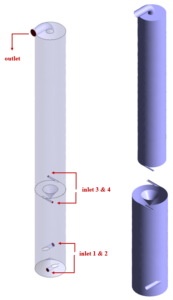
The present 3-D model is designed using Design Modeler software. The geometry of the model consists of a two-piece cylindrical chamber 7.5 m long and 0.8 m in diameter So that the upper part has a length equal to 5 m and the lower part has a length equal to 2.5 m. The lower part consists of two cones on either side of it in opposite directions;
So that the cone in the middle of the chamber has a diameter of 0.6 m and a height of 0.3 m, and the cone at the bottom of the chamber has a diameter of 0.8 m and a height of 0.35 m. There are two pipes for fuel inlet in the lower part of the chamber, in the form of a narrow cylinder with a diameter of 0.1 m but in opposite directions to each other and at an angle of 180 degrees.
The two pipes for liquid water inlet are located in the middle of the chamber, in the form of a narrow cylinder with a diameter of 0.05 m but in opposite directions to each other and at an angle of 180 degrees. The product outlet pipe with a diameter of 0.2 m is placed at the top of the chamber. The figure below shows a view of the geometry.
The meshing of the model has been done using ANSYS Meshing software and the mesh type is unstructured. The element number is 219170. The following figure shows the mesh.
Gasification CFD Simulation
To simulate the present model, several assumptions are considered:
- We perform a pressure-based solver.
- The simulation is steady.
- The gravity effect on the fluid is ignored.
A summary of the defining steps of the problem and its solution is given in the following table:
| Models (Gasification) |
||||
| Viscous | k-epsilon | |||
| k-epsilon model | standard | |||
| near-wall treatment | standard wall function | |||
| Radiation model | P1 | |||
| Species model | Species transport | |||
| reactions | volumetric | |||
| mixture species | O2, N2, CH4, H2, CO2, H2O, air | |||
| Discrete phase model | On | |||
| Injection | active | |||
| Injection
1 & 2 anthracite |
particle type | Inert | ||
| injection type | surface | |||
| point properties | temperature | 393.15 K | ||
| velocity magnitude | 30 m.s-1 | |||
| diameter | 0.000001 m | |||
| total flow rate | 0.2 kg.s-1 | |||
| Injection
3 & 4 water-liquid |
particle type | droplet | ||
| injection type | surface | |||
| point properties | temperature | 673.15 K | ||
| velocity magnitude | 122 m.s-1 | |||
| diameter | 0.000001 m | |||
| total flow rate | 0.02 kg.s-1 | |||
| Energy | On | |||
| Boundary conditions (Gasification) |
||||
| Inlet-1 & Inlet 2 | Velocity inlet | |||
| velocity magnitude | 30 m.s-1 | |||
| temperature | 393.15 K | |||
| internal emissivity | 1 | |||
| all species mass fractions | 0 | |||
| discrete phase BC type | escape | |||
| Inlet-3 (up-down) &
Inlet 4 (up-down) |
Velocity inlet | |||
| velocity magnitude | 122 m.s-1 | |||
| temperature | 673.15 K | |||
| internal emissivity | 1 | |||
| all species mass fractions | 0 | |||
| discrete phase BC type | escape | |||
| Wall-up
& Wall-down |
Wall | |||
| wall motion | stationary wall | |||
| heat flux | 0 W.m-2 | |||
| internal emissivity | 1 | |||
| all species boundary conditions | zero diffusive flux | |||
| discrete phase model conditions | reflect | |||
| Outlet | Pressure outlet | |||
| gauge pressure | 0 Pascal | |||
| internal emissivity | 1 | |||
| discrete phase BC type | escape | |||
| Methods (Gasification) |
||||
| Pressure-velocity coupling | SIMPLE | |||
| pressure | second order | |||
| momentum | second order upwind | |||
| turbulent kinetic energy | first order upwind | |||
| turbulent dissipation rate | first order upwind | |||
| H2O – O2 – N2 – CH4 – CO – H2 – CO2 | second order upwind | |||
| energy | second order upwind | |||
| Initialization (Gasification) |
||||
| Initialization methods | Standard | |||
| velocity (x,y,z) | 0 m.s-1 | |||
| temperature | 400 K | |||
| gauge pressure | 0 Pascal | |||
| H2O | 0.3 | |||
| O2 – N2 – CH4 – CO – H2 – CO2 | 0 | |||
Results
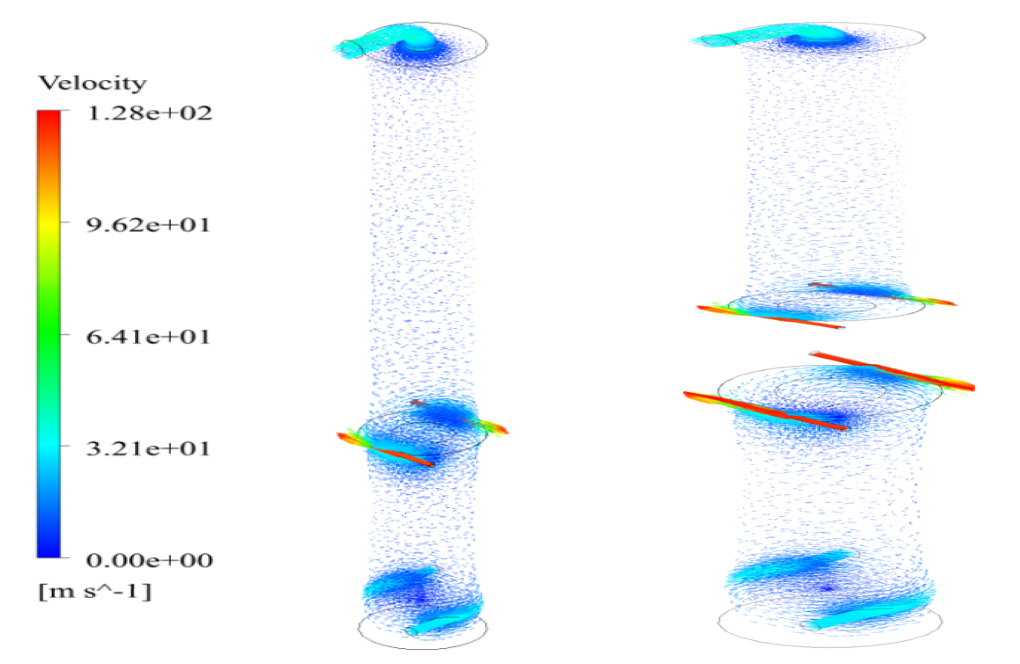
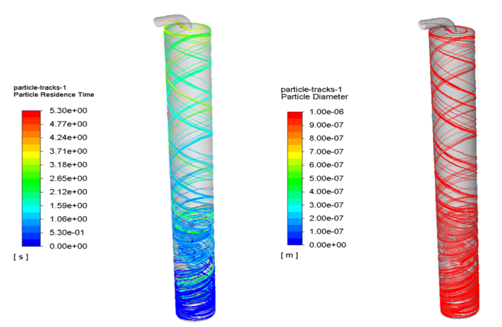
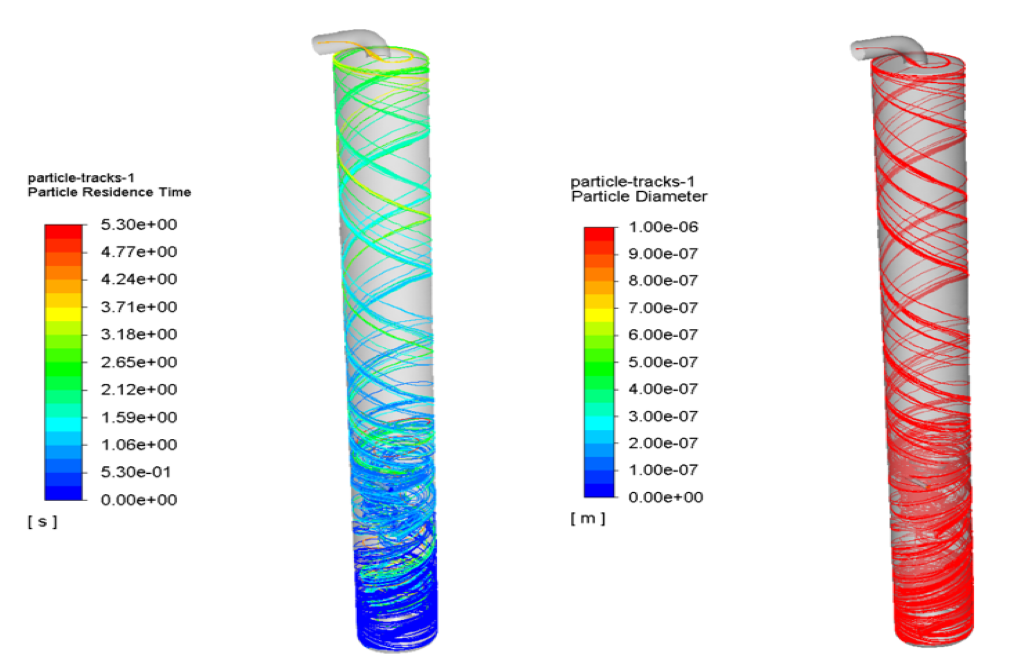
At the end of the solution process, three-dimensional temperature and velocity counters, three-dimensional velocity vectors, and a particle track are obtained.




Easton Boyle –
you guys have a simulation for everything, don’t you? It’s like a candy store for CFD enthusiasts!
MR CFD Support –
Thank you for your feedback! We strive to cover a wide range of topics and applications to cater to the diverse needs of our customers.
Cyrus Schuppe –
What is the main purpose of this Gasification CFD Simulation?
MR CFD Support –
This simulation is designed to analyze the process of gasification, which is a thermochemical process that converts organic or fossil-based carbonaceous materials into carbon monoxide, hydrogen, and carbon dioxide.
Prof. Florida Monahan III –
I’m particularly interested in how the P1 radiation model is implemented in this kind of simulation. Could you provide more details on how it contributes to the overall accuracy of the gasification process simulation?
MR CFD Support –
In this simulation, the P1 radiation model helps in accurately predicting the thermal radiation effects, which are crucial in high-temperature processes like gasification. It simplifies the calculation by assuming that radiative heat flux is divergence free. The model is particularly useful for predicting the heat transfer in optically thick and participating media, which is the case for the combustion gases in the gasifier chamber. The inclusion of the P1 radiation model ensures that the influence of thermal radiation on the temperature distribution and the reaction kinetics in the gasification process is considered, enhancing the accuracy of the simulation results.
Tyrique Homenick –
Can this simulation be customized to model a specific gasification process?
MR CFD Support –
Yes, we can accommodate your desired simulations. Please share more details about your specific process.
Mr. Bertram Weimann –
Your work is truly impressive. Keep it up!
Marina Greenholt –
How are the results of the simulation visualized?
MR CFD Support –
The results are visualized using contour plots of pressure, temperature, and species concentration, as well as pathlines of the flow.