Biomass Combustion CFD Simulation, ANSYS Fluent Training
$220.00 $110.00 Student Discount
- The problem numerically simulates the biomass combustion process inside a gasifier chamber using ANSYS Fluent software.
- We design the 2-D model by the Gambit software.
- We Mesh the model by Gambit software, and the element number equals 1108.
- We use the DPM model to define spraying the fuel in the chamber as discrete particles.
- We define Non-Premixed Combustion in the Species model.
- We use the P1 Radiation model to define radiant heat energy from the flames.
To Order Your Project or benefit from a CFD consultation, contact our experts via email (info@mr-cfd.com), online support tab, or WhatsApp at +44 7443 197273.
There are some Free Products to check our service quality.
If you want the training video in another language instead of English, ask it via info@mr-cfd.com after you buy the product.
Description
Description
The present problem simulates the biomass combustion process inside a gasifier chamber by ANSYS Fluent software. We perform this CFD project and investigate it by CFD analysis.
The material used for combustion is biomass, which reacts with the oxidizer. It is a biomass substance made from wheat straw that reacts with oxygen to produce synthetic gas as a healthy fuel, and various gas species are involved as reactants or products.
Fuel containing biomass and air enters the chamber from two separate inlets from the upper area. It creates a mass of materials, including ash and semi-combustible coal, in the lower part of the chamber. Finally, the resulting gas is discharged from the outlet at the bottom of the chamber to the next stage, entering the relevant boiler to create the combustion process.
We design the present 2-ِD model and its mesh using Gambit software. The mesh type is unstructured, and the element number is 1108.
Biomass Methodology
In this project, we use the Species model. Since the inlets of air and the fuel are separated, the fuel and oxidizer do not combine before entering the inner space of the chamber. So, we define the reaction as Non-premixed.
We import a PDF (probability density function) file to define the non-premixed combustion. It’s a mixture consisting of biomass, air, and other gaseous species with a rich flammability limit of the fuel flow equal to 0.1 in Fluent software.
Also, the fuel must enter the chamber as discrete particles. It means that the injection of this substance into the chamber is defined based on the Lagrangian view. Therefore, we use the Discrete Phase Model (DPM).
In addition, we define the Radiation model since there is radiant heat energy from the flames in the combustion process. In the present model, we use the P1 model. It’s because the process is related to combustion, and the thickness of its optical layer is high.
Biomass Conclusion
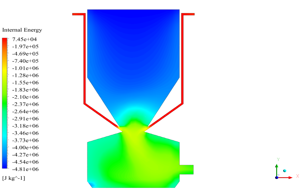
In conclusion, we obtain two-dimensional contours related to pressure, temperature, velocity, and density. We also obtain species mass fraction, water and vapor mass fraction, and radiation temperature.
The results show that, as expected, combustion is formed and performed with the arrival of fuel particles, and the combustion chamber temperature is raised.
The velocity has its maximum value due to the accumulation of particles in the small inlet surface in the inlet area. The highest temperature occurred in the nozzle opening. The results also show the accumulation of soot in the output area of the geometry.


Velda Dicki –
The training was practical, and I think it can be beneficial.
Prof. Alanis Homenick –
Thank you for this excellent tutorial; the teacher is fluent in the topics and clearly explains everything.
Miss Dovie Koch I –
Can this simulation be customized to model different types of biomass and gasification conditions?
MR CFD Support –
Yes, we can accommodate your desired simulations. Please share more details about your specific requirements.
Vladimir Pfannerstill DDS –
Can this simulation be used to optimize the design of biomass gasification systems?
MR CFD Support –
Absolutely! The results from this simulation can provide valuable insights into the combustion process and the performance of the gasifier, which can be used for design optimization.
Prof. Wendell Schulist II –
I found it incredibly fascinating that the biomass is introduced as discrete particles. Can you elaborate on the considerations regarding the sizing and properties of the particles in the simulation settings?
MR CFD Support –
In the biomass combustion simulation, particle sizing and properties are carefully chosen to accurately represent the real-world characteristics of wheat straw particles. The Discrete Phase Model (DPM) requires the definition of particle size, density, as well as the material properties of the biomass, including its heating value and moisture content. Additionally, parameters like particle injection velocity, temperature, and feed rate need to be set in alignment with the combustion chamber’s operating conditions to achieve realistic simulation results.
Mr. Royal West DDS –
The learning materials were very detailed, making understanding the biomass combustion process clear and straightforward. The intertwining of theory and software application was particularly beneficial.
MR CFD Support –
Thank you for your kind words! We’re delighted to hear that you found our biomass combustion CFD simulation course both detailed and easy to follow. Your feedback is greatly appreciated, and we’re glad the course enhanced your understanding effectively. If there’s anything else you’d like to learn or need further assistance with, please don’t hesitate to let us know!
Ms. Aryanna Feil –
I’m curious about the probability density function in this simulation. Could you please explain how the PDF is used in the biomass combustion process, and how it affects the results?
MR CFD Support –
The probability density function (PDF) in biomass combustion simulations is essential for predicting the mixture fraction of fuel, oxidizer, and combustion products within the gasifier. It enables the modeling of chemical reactions and their rates under non-homogeneous conditions. In ANSYS Fluent, the PDF is imported to define the non-premixed combustion characteristics, accounting for variations like temperature and chemical species concentration gradients. This impacts results by providing a more accurate prediction of species distribution, temperature, and velocity within the chamber, which are vital for understanding the combustion efficiency and product gas composition.
Chet Collier –
I was wondering how the Discrete Phase Model (DPM) you mentioned contributed to the biomass combustion simulation? Did it enhance the accuracy of predicting the behavior of the biomass particles during combustion?
MR CFD Support –
In the context of biomass combustion simulation, the Discrete Phase Model (DPM) is crucial for tracking individual biomass particles as they flow, heat up, react, and potentially burn out within the gasifier chamber. Using DPM allows for a more accurate prediction of how biomass particles actually behave and interact with the surrounding combustion environment, including responses to temperature changes, reactions with the oxidizer, and subsequent gas formations. This contributes substantially to the overall accuracy and robustness of the CFD model in predicting the combustion of biomass.
Dr. Neha Walker –
Is it possible to track the individual particles during the simulation to study their behavior and the combustion process in detail?
MR CFD Support –
Yes, in ANSYS Fluent Discrete Phase Model (DPM), you can track the trajectory of individual particles, monitoring various parameters like their temperature, mass, and reaction progress to better understand the combustion process and the behavior of particles within the reactor.
Ulices Schneider –
I’m interested in how efficient the combustion is in this simulation. Does the simulation provide data regarding the complete burn or chances of incomplete combustion?
MR CFD Support –
The simulation does provide insights into combustion efficiency. It reveals information about the combustion completeness by showing temperature distribution and species mass fractions. One can observe the presence of semi-combustible materials and ash in the lower part of the chamber, indicating areas where incomplete combustion may occur. This is further clarified by examining the mass fractions of various gas species, which signify how effectively the biomass is burning.
Holly Rogahn I –
It was great and perfect.
Dr. Ursula Flatley MD –
In the simulation of biomass combustion, can you explain how the application of the P1 radiation model influences the outcome compared to other radiation models?
MR CFD Support –
The P1 radiation model is specifically chosen for this biomass combustion simulation because of its suitability for media with high optical thickness where radiation plays an important role. By accounting for the heat transfer due to radiation, which is significant in combustion processes, the P1 model enhances the accuracy of temperature distribution and heat flux predictions within the combustion chamber. This choice directly affects the simulation results by providing a more realistic representation of the thermal field in such high-temperature environments, compared to other models that may neglect important radiation effects or might not be as suitable for optically thick media.
Mrs. Susana Hartmann –
I just completed the biomass combustion simulation course and I love how well-explained the concept of biomass as a renewable energy source was. The step-by-step breakdown of the setup really solidified my understanding. Great job!
MR CFD Support –
Thank you for your feedback! We’re thrilled to hear that our course helped enhance your understanding of biomass combustion. Your enthusiasm for learning is what inspires us to keep improving our training materials!
Brook Leuschke –
I’m impressed by the level of detail in the biomass combustion CFD simulation training. The comprehensive approach to simulating the gasification process is exceptional.
MR CFD Support –
Thank you for your positive feedback! We are delighted to hear that the level of detail in our biomass combustion CFD simulation training has impressed you. It’s great to know that the comprehensive approach to the subject was exceptional. If you have any more questions or need further assistance with our training materials, please don’t hesitate to reach out.
Jacklyn Douglas I –
This biomass combustion simulation seems very comprehensive. What is the maximum temperature reached in the nozzle opening?
MR CFD Support –
The precise numerical value of the maximum temperature reached in the nozzle opening is specific to the simulation settings and the combustion process’s dynamics. Unfortunately, without access to the simulation results, I cannot provide the exact temperature value. The simulation report or the results section in the software would have this detail.
Mr. Wilson Hand DVM –
Do the provided training materials discuss how to set up the Discrete Phase Model (DPM) for fuel particle injection in detail?
MR CFD Support –
Yes, the Discrete Phase Model (DPM) for fuel particle injection setup is thoroughly discussed in the training materials to guide you through the process of setting up simulations for biomass combustion effectively.
Jerad Krajcik –
Is it possible to adjust the biomass particle size in the DPM to see how it affects combustion efficiency?
MR CFD Support –
Indeed, you can modify the biomass particle size within the Discrete Phase Model settings to study how changes in particle size may impact the overall combustion efficiency. Simulations can be re-run with different particle sizes to compare results.
Dr. Mabelle Feeney –
I was wondering about the initial conditions for the biomass and air before they entered the chamber. Could you explain how they were set up for the simulation?
MR CFD Support –
The initial conditions for the biomass and air in the simulation were set to specific values to accurately represent their physical state before entering the combustion chamber. The biomass was treated as discrete particles with prescribed size and distribution, while the air inlet carried ambient temperature and a calculated oxidizer mass flow rate necessary for complete combustion with the given amount of biomass.
Dion Gibson –
I especially appreciate the clarity of the given results on biomass combustion. Was any specific calibration needed to match the simulation results with experimental or real-life data?
MR CFD Support –
Thank you for your compliment! To ensure accuracy in our simulations, we always aim for close alignment with empirical data. For this particular simulation, we performed standard calibrations through sensitivity analyses and tuning of input parameters within ANSYS Fluent, adapting boundary conditions and material properties to refine the model. However, any necessary specific calibrations were made in accordance with reliable reference data or experimental results to ensure the validity of our simulation outcomes in capturing the complex processes of biomass combustion.
Prof. Loyce Buckridge IV –
Is the model capable of predicting emissions from the biomass combustion process as well?
MR CFD Support –
The model described, with the Species model and non-premixed combustion settings, is indeed capable of predicting emissions from the biomass combustion process. It can track various gas species which are byproducts of the combustion reaction. Moreover, using the Species mass fraction results, the simulation can provide insight into the amount of emissions, including soot accumulation, produced during the combustion.
Tabitha Berge –
Can you also determine the energy efficiency of the combustion process using this simulation?
MR CFD Support –
In this simulation, it primarily focuses on the combustion behavior and pollutant formation through temperature and species mass fraction contours. To determine energy efficiency quantitatively, one would need to assess the energy input compared to the energy output. This can be done through additional analyses by considering the heating value of the biomass, the outlet gas energy content, and heat losses, which is usually not directly calculated from typical combustion CFD simulations but can be estimated using the simulation data.
Vidal Ratke –
I’m blown away by the Biomass Combustion CFD Simulation training—it provided a deep understanding of complex processes like non-premixed combustion and radiation modeling with P1. All the visualization of combustion chamber phenomena adds tremendous value to the learning experience.
MR CFD Support –
Thank you so much for your positive feedback! We are thrilled to hear that you found the training on Biomass Combustion CFD Simulation in ANSYS Fluent informative and valuable. It’s always encouraging to know that our efforts to provide detailed and visualized learning materials are appreciated. If you have any further questions or require additional learning resources, please do not hesitate to reach out.
Jacques Lynch –
I’d like to know more about how you condition and handle the biomass before it enters the combustion chamber. Are there any preprocessing steps required for the particle size or moisture content of the biomass fuel?
MR CFD Support –
In this simulation scenario, preprocessing of the biomass, like controlling particle size or moisture content before entry, would be an important part of the combustion process setup. However, this information hasn’t been detailed in the description provided. Understanding how biomass treatment affects combustion simulation results is crucial, and typically in real applications, biomass is ground to a consistent particle size, and moisture content is reduced to improve combustion efficiency.