H-Type Vertical Axis Wind Turbine (VAWT), Mesh Motion
$140.00 $70.00 Student Discount
- The problem numerically simulates H-type vertical axis wind turbine using ANSYS Fluent software.
- We design the 3-D model by the Design Modeler software.
- We Mesh the model by ANSYS Meshing software, and the element number equals 1546624.
- We perform this simulation as unsteady (Transient).
- We use the Mesh Motion moethod to define rotational movement.
To Order Your Project or benefit from a CFD consultation, contact our experts via email (info@mr-cfd.com), online support tab, or WhatsApp at +44 7443 197273.
There are some Free Products to check our service quality.
If you want the training video in another language instead of English, ask it via info@mr-cfd.com after you buy the product.
Description
H-Type Vertical Axis Wind Turbine (VAWT) CFD Simulation Applying ANSYS Fluent Mesh Motion Method, Tutorial
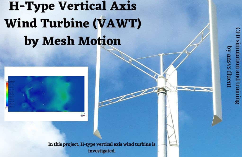
This simulation is about an H-type vertical axis wind turbine (VAWT) via ANSYS Fluent software. We perform this CFD project and investigate it by CFD analysis.
Nowadays, turbines are a reliable, clean energy source that generates electricity using the induced rotation by wind flow. However, turbine wind farms face challenging issues such as low efficiency at lower diameters for horizontal axis turbines (HAWT), disruption of the natural view of valleys, and low wind conditions.
These three problems can be solved using Vertical Axis Turbines (VAWT), where diameters as large as 200 m, commonly used in HAWTs, do not need. VAWTs are widely used offshore. Disruption of natural view is overcome, and wind conditions are more predictable and reliable in offshore wind farms.
The H-type turbine analyzed in the present work has six blades with three blades closer to the center of rotation. The turbine rotates in a -Z direction with an angular velocity equal to 14.17 rad/s. Air velocity at the inlet is equal to 5.3 m/s.
Airflow in the domain is dominantly affected by turbine rotation. Maximum air velocity in the domain is equal to 45 m/s, which is captured downstream of the turbine.
The geometry of the present model is drawn by Design Modeler software. The model is then meshed by ANSYS Meshing software. The model mesh is unstructured, and 1546624 cells have been created.
H-type Turbine Method
In this simulation, the rotational motion of the turbine blades must be defined. But instead of applying rotational motion to the blades, rotational motion is applied to the field around the blades. So, it is necessary to separate a distinct zone as the moving zone from the total computing zone. Since this turbine is one of the vertical axis turbines, the behavior of the fluid is dependent on time; because the position of the turbine blades varies over time. Then the Mesh Motion is used in cell zone conditions. In this method, the rotation axis and rotation speed must be determined.
H-type Turbine Conclusion
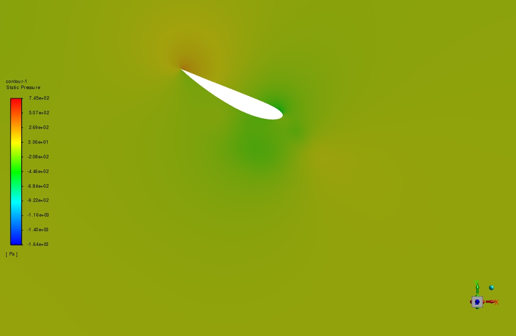
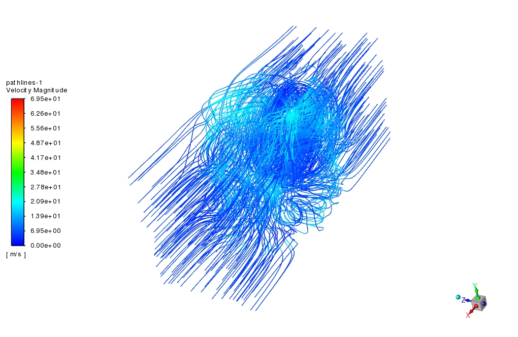
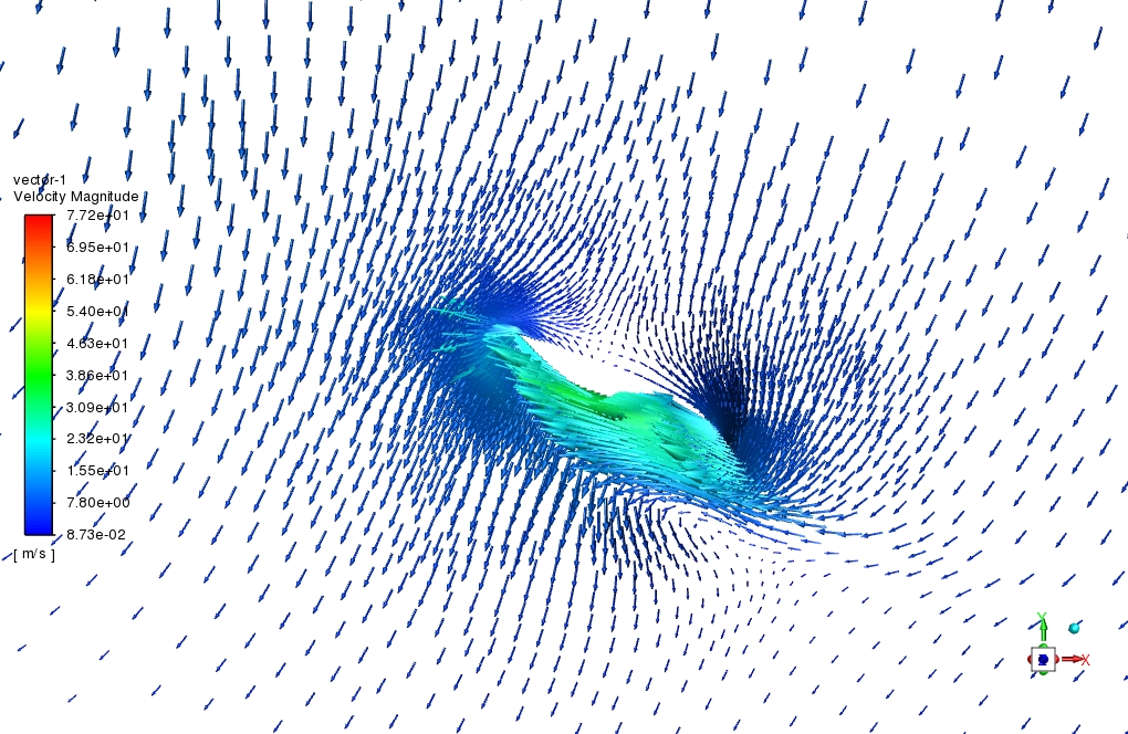
After simulation, the contours of velocity and pressure are obtained. Also, velocity vectors and pathlines around the turbine blades are obtained. The results show that the wind flow around the turbine blades has a rotational movement. The air mass flow rate at the inlet is equal to 272.685 kg/s.
The turbine blade’s tip speed ratio (TSR) is almost equal to 6, where tip speed and free stream velocity are equal to 30 and 5.3 m/s. According to rotation and free stream flow direction, there is a stagnation point in the minus Y direction of the turbine, which also represents the maximum pressure zone.
The combined effect of free stream flow and flow generated due to rotation differs on the inner and outer blades. On the internal blades, the pressure difference is less than on the outer blades. This can result from the higher linear velocity of the outer blades than the inner blades.


Malinda McLaughlin III –
Can this simulation be used to optimize the design of a vertical axis wind turbine?
MR CFD Support –
Absolutely! The simulation provides detailed insights into the flow behavior and aerodynamic forces on the turbine blades, which can be used to optimize the turbine design for improved performance.
Lexie Mayert –
Can the simulation predict the torque on the turbine shaft?
MR CFD Support –
Yes, the simulation can predict the torque on the turbine shaft by calculating the moment of the aerodynamic forces about the shaft axis.
Constantin Tremblay –
Truly comprehensive and insightful simulation output! The results around the blade tips showing reduced pressure on the internal blades versus the outer blades were particularly interesting. It seems like your findings could heavily influence turbine design optimization for performance enhancement in VAWTs. Great job!
MR CFD Support –
Thank you for your kind words! We are delighted to hear that the simulation insights were helpful and informative. Customer feedback is valuable to us, and we appreciate your recognition of our efforts to optimize VAWT performance through CFD analysis. If you have further inquiries or need support on your own projects, don’t hesitate to reach out!
Dr. Gillian Greenholt DDS –
The explanation of the H-type turbine simulation is fantastic! It provided a clear understanding of the methodology and important aspects like TSR and their effect on turbine performance.
MR CFD Support –
Thank you so much for your kind words! We are thrilled to know that our tutorial on the H-type vertical axis wind turbine was helpful and informative for you. Your feedback is greatly appreciated, and if you have any other questions or need further clarification on any aspect of the simulation, don’t hesitate to reach out to us!
Kayley Nitzsche –
I am thrilled with how the Mesh Motion method was applied in this simulation! It really helped to understand how rotation impacts airflow around the blades.
MR CFD Support –
Thank you for your kind words! We’re glad the Mesh Motion method in the simulation of the H-Type VAWT provided clear insight into the aerodynamic behaviors involved. Your appreciation means a lot to us, and we’re thrilled our tutorial was helpful. If you have any more questions or need further clarifications, feel free to reach out!
Dr. Edna Watsica PhD –
The results for tip speed ratio and stagnation points were particularly interesting! Really illustrated the complex dynamics involved. Great material for a better understanding of VAWT designs and performance.
MR CFD Support –
Thank you for sharing your thoughts on the simulation of the H-Type Vertical Axis Wind Turbine using ANSYS Fluent Mesh Motion Method! We are glad to hear that the material provided valuable insights into VAWT designs. Your feedback is greatly appreciated, and we hope the tutorial was informative and beneficial to your research or projects.
Hayley Upton –
I am very impressed with the detailed explanation of the H-Type VAWT simulation using the mesh motion method. Could you please share what criteria were used to determine the mesh quality in this particular simulation?
MR CFD Support –
We are thrilled to hear you’ve enjoyed the explanation! The mesh quality for this simulation of the H-Type VAWT using the mesh motion method is typically determined based on factors such as skewness, aspect ratio, orthogonal quality, and smoothness transitions between cell sizes. The meshes are refined in areas of high gradient (near the rotating blades, in this case) to accurately capture the flow phenomena. Both ANSYS Meshing software’s quality diagnostics tools and convergence criteria during the simulation help ensure that the created mesh can capture the essential flow characteristics around the turbine effectively.
Mr. Brenden Brakus –
The results sound great! Does this simulation take into account the varying wind conditions that can occur in offshore environments?
MR CFD Support –
Thank you for the compliment! The simulation is designed around a specific uniform wind condition with a constant inflow velocity to assess and simulate the performance of the H-Type VAWT. Real-world offshore wind conditions can indeed vary, and these could potentially be investigated with additional simulations that include gusting and varying wind profiles.
Misael Kemmer –
The review perfectly explains the attention to detail in this simulation. The clear distinction between inner and outer blades and their effect on airflow is impressive.
MR CFD Support –
Thank you for your positive feedback! We are thrilled to hear that our attention to detail and clear explanations in the H-Type VAWT simulation have met your expectations. We strive to provide comprehensive and insightful analyses in all our simulations. If you have further inquiries or need more information, please feel free to reach out!
Patsy Upton –
I am thrilled with the dynamic visualization of the VAWT simulation; the rotating airflow truly helps understand the interactions! Can you clarify how the speed ratio is determined and what its significance is in the analysis?
MR CFD Support –
Sure, the tip speed ratio (TSR) is determined by the ratio of the blade tip speed to the free stream wind velocity. The TSR is significant because it gives insight into the efficiency of the turbine; an optimum TSR value suggests that the turbine is producing energy at or near its maximum potential efficiency for the current wind speed.
Hulda Tremblay IV –
Amazing clarity on the Mesh Motion and its implications on simulating the VAWT’s dynamics. I particularly appreciated the results section detailing the turbine blade’s TSR and stagnation points affecting pressure distribution.
MR CFD Support –
Thank you for your positive review! We’re glad to hear that you found the explanation on Mesh Motion and the resulting dynamics of the VAWT insightful and easy to understand. It’s fantastic that the details provided on the turbine’s operation and the pressures involved added real value to your understanding of the simulation. Your feedback is much appreciated!
Brian Cummerata DDS –
I’m impressed by the detail and thorough analysis of the H-Type Vertical Axis Wind Turbine (VAWT). It’s intriguing how the mesh motion method is employed to simulate the rotational movement around turbine blades. Kudos to the team for carrying out such comprehensive work.
MR CFD Support –
Thank you for the positive feedback! We’re thrilled to hear that you are impressed with the level of detail and thoroughness of the H-Type VAWT simulation utilizing the mesh motion method. Our team strives for excellence in providing comprehensive CFD analyses, and your compliments are truly appreciated.
prem kumar naik –
sir, your simulations are really awesome. how much torque and efficiency did you get? My name is Prem Kumar Naik from IIT Kharagpur, I am also working on a project for a wind turbine on mars. can you please share those data (how much efficiency did you get) with me? my email is premnaikmude@iitkgp.ac.in,Thank you
Dr. Leonie Waters –
This product is exceptional at illustrating the complexities of modeling an H-Type VAWT. By visualizing the effects of blade rotation on airflow, the simulation offers a practical insight into wind turbine operation and efficiency that simple theoretical models miss.
MR CFD Support –
Thank you for sharing your positive experience with our H-Type VAWT simulation tutorial! We are pleased that you find the product provides practical and complex modeling insights. It’s great to know that it helped enhance your understanding of wind turbine dynamics. If you need any further information or assistance on our simulations, feel free to reach out.
Prof. Garry Marquardt –
The tutorial for the H-Type VAWT was so clear and precisely what I needed as a reference for my project on sustainable energy solutions. The application of the Mesh Motion Method was especially enlightening!
MR CFD Support –
Thank you for your positive feedback! We’re thrilled to hear the tutorial for the H-Type Vertical Axis Wind Turbine using the Mesh Motion Method was helpful for your sustainable energy project. Your success is our reward. If you ever have any more queries or need further assistance, our team is always here to help!
Dr. Glen Murray –
The simulated results for the H-Type VAWT look promising! I’m particularly impressed by the way you’ve managed to capture the complex rotational movements and their effects. It’s great to see that Vertical Axis Wind Turbines are being given attention as a sustainable energy solution, especially with their offshore applications in mind where they have the advantage over HAWT.
MR CFD Support –
Thank you for the positive feedback on the H-Type Vertical Axis Wind Turbine CFD simulation! We’re glad to hear that you appreciate our efforts to explore innovative, sustainable energy solutions using advanced simulation methods. If you have any further inquiries or need additional information, feel free to ask.
Mozelle Reynolds –
How does the simulation model the rotation of the turbine blades?
MR CFD Support –
The simulation uses the mesh motion method to model the rotation of the turbine blades. This method involves moving the mesh nodes in the computational domain to simulate the rotation of the blades.
Frida Lindgren –
I found the information about the rotational motion applied to the field around the blades instead of the blades themselves very interesting. Can you please elaborate on how the performance differs when using this mesh motion approach compared to directly rotating the blades?
MR CFD Support –
Using the mesh motion approach allows the entire fluid domain around the blades to be set in rotational motion rather than directly rotating the solid blades. This can simplify the computational model and reduce computational costs by not requiring the mesh to conform to the moving solid boundaries of the blades. The results between both approaches could vary, with the mesh motion technique possibly providing a good approximation of performance while being computationally less intensive, although this can depend on factors such as mesh quality, rotation speed, and accuracy of the defined boundary layer around the blades.
Dr. Lexi Carroll DDS –
The results of the VAWT simulation sound intriguing! I’m particularly interested in how the Mesh Motion method improves the CFD simulation. Could you explain the advantages of using Mesh Motion for this type of simulation?
MR CFD Support –
Using the Mesh Motion method in this type of CFD simulation allows for the dynamic tracking of the rotating blades of the VAWT without the need to actually rotate the geometry. The mesh surrounding the blades is treated as a separate zone that moves, thereby capturing the effects of rotation and time-dependence in the wind flow pattern. This approach enables accurate computation of fluid forces on the rotating blades, prediction of performance under varying wind conditions, and the adaptation of the mesh during the simulation to maintain the quality necessary for accurate results. Mesh Motion is particularly advantageous for complex, moving geometries and provides a more computationally efficient alternative to physically rotating the actual geometry.
Juanita Schamberger DVM –
I am impressed by how the challenges in horizontal axis wind turbines are tackled with the use of vertical axis wind turbines in this study. Great CFD analysis of the H-type VAWT using the mesh motion method.
MR CFD Support –
Thank you for your positive feedback! We’re glad that our simulation on H-type Vertical Axis Wind Turbines provided clear insights and addressed significant challenges in the field. Should you have any questions or need further information about our simulations, feel free to reach out.
Prof. Toni Robel –
Very impressed with the H-Type VAWT simulation and the detailed inclusion of TSR and pressure contours. Are the visual results clear enough to see the pressure differences between the internal and outer blades?
MR CFD Support –
Thank you for your kind words! We’re glad to hear that you found the simulation results impressive. Yes, the visual results are designed to be clear, allowing you to see the difference in pressure between internal and outer blades effectively. The contours of pressure in the simulation showcase these differences distinctly, aiding in a comprehensive analysis of the wind turbine’s performance.
Taylor Green –
I appreciated the practical aspect of the H-Type VAWT simulation tutorial in handling mesh motion setup. Is there any supplementary content I can access for further understanding of mesh interactions during rotation?
MR CFD Support –
We’re glad to hear that you found the tutorial beneficial! You can find additional resources, such as webinars, detailed user guides, or extra case studies on mesh interaction effects in rotating bodies on our website or by reaching out to our support team who can provide tailored materials suited to your interests.
Marian Wiza –
After performing the simulation, could we estimate the power output of the H-Type VAWT based on the obtained results? And if so, which of the results would be most crucial for this calculation?
MR CFD Support –
Yes, after performing the simulation, we can estimate the power output of the H-Type VAWT. The most crucial results for calculating the power output would be the torque generated on the blades due to the air pressure difference. Additionally, knowing the angular velocity (given as 14.17 rad/s) and tip speed ratio (TSR) helps in calculating the mechanical power. A formula including the torque (τ) and angular velocity (ω) is used: Power (P) = τ * ω.
Prof. Cory Feeney –
This product completely surpassed my expectations! The level of detail in both the tutorial and simulation for the H-Type Vertical Axis Wind Turbine was excellent. Understanding the impact of the blade’s rotation on wind flow and how you faithfully recreated this dynamic in ANSYS Fluent mesh motion gives me immense confidence in the accuracy of the CFD analysis. This will be immensely helpful for my project on renewable energy sources. The visuals of velocity vectors and pathlines were particularly insightful. Keep up the great work!
MR CFD Support –
We’re thrilled to hear that our H-Type Vertical Axis Wind Turbine (VAWT) simulation tutorial was able to provide you with the details and insight you needed for your renewable energy project. It’s always rewarding to know our products are making a positive impact on our customers’ work. Thank you for taking the time to share your kind words and positive experience. We look forward to delivering more quality simulations and tutorials!
Pietro Collier –
The tutorial you provided for the H-Type VAWT simulation using Mesh Motion in ANSYS Fluent was fantastic. The images and explanations made the complex concepts clear, and the step-by-step approach was very effective for my learning. Great job!
MR CFD Support –
Thank you for your positive feedback on the H-Type VAWT CFD Simulation tutorial! We’re thrilled to hear that our resources made such a complex topic clear and accessible for you. If you need further assistance or have any more questions as you continue to explore CFD simulations, please don’t hesitate to reach out.
Daron Hermiston –
I found the TSR value mentioned interesting. Can you explain how applying Mesh Motion enhances the simulation results for the VAWT?
MR CFD Support –
Using Mesh Motion for the H-type VAWT simulation allows the mesh to adapt to the moving parts of the turbine. This means the turbine blades can physically rotate within the simulation, providing a more detailed and accurate representation of the interactions between the wind and rotating blades. Hence, this leads to a more realistic prediction of performance characteristics like the turbine’s TSR, flow patterns, and pressure distribution, thus enhancing the overall quality of the CFD analysis.
Celia Jerde –
The simulation results reflect a comprehensive understanding of the turbine’s operation. Great job on the visualization of the airflow and pressure contours. It’s really effective how they express the rotor’s performance.
MR CFD Support –
Thank you for your positive feedback on our H-Type VAWT simulation and its visualization features. We are delighted to know that our work meets your expectations and provides a clear understanding of the turbine’s aerodynamics and performance.
Blanche Howe –
Your presentation and analysis of the H-Type VAWT was comprehensive and nodded to several benefits, including less visual disruption and adaptable scale. I was particularly interested in the different behavior exhibited between the internal and outer blades. Thank you for such an informative assessment!
MR CFD Support –
Thank you for your positive feedback! We’re thrilled to hear that you found the information about the H-Type vertical axis wind turbine and its blade behavior insightful. Our goal is to provide thorough and understood analysis that is beneficial to our users. If you have any more questions or need further assistance with wind turbine design and analysis, feel free to reach out!
Santos Crist –
I was impressed with how dynamic structures like the VAWT are simulated. How does the simulation using Mesh Motion account for the variable positions of the blades over time, and how is it different from simply applying a rotational movement to the blades?
MR CFD Support –
In the Mesh Motion technique, the entire mesh surrounding the turbine blades is set in motion instead of individually rotating the blades. This means that a distinct ‘moving zone’ is defined in the computational domain, and it is this section of the mesh that is set to rotate. The rotation axis and angular velocity are specified for the entire zone, emulating how the fluid movement is influenced by the turning blades. The key difference from merely rotating the blades is that with Mesh Motion, the mesh grid itself adapts to the rotational motion, providing more accurate simulation of the fluid dynamics as the turbine rotates.
Mrs. Valentina Paucek II –
I’m really impressed with how the simulation considers both the rotational movement of the turbine and the airflow! Could the rotation axis and rotation speed parameters be adjusted easily if different wind conditions were being tested?
MR CFD Support –
Yes, the rotation axis and rotation speed can be adjusted easily in the ANSYS Fluent environment. You can redefine these parameters in the ‘cell zone conditions’ to simulate different wind conditions and obtain the corresponding effects on the turbine’s performance.
Toni Marks –
This tutorial made setting up the mesh motion for the VAWT seem straightforward. The visualization of airflow patterns was particularly helpful to understand turbine efficiency. You mentioned a stagnation point, how does the presence of a stagnation point affect the performance of the H-Type Turbine?
MR CFD Support –
The presence of a stagnation point on the H-Type Turbine indicates the region where the airflow is momentarily at rest relative to the turbine blade. This is typically where the relative airflow has the highest pressure and meets the blade face directly. Understanding the stagnation point’s location helps in optimizing the turbine’s design to reduce drag and maximize lift, therefore improving the performance. However, it is worth considering that any prolonged high-pressure regions can increase structural stress and may affect the long-term durability of the turbine.
Alvis Jakubowski –
What an insightful simulation of the H-type VAWT using the Mesh Motion Method! I’m delighted to see the methodical approach to boundary conditions and the detailed analysis of velocity and pressure contours. Plus, considering rotational effects in airflow around the turbine and assessing tip speed ratio offers a comprehensive understanding that’s vital for optimizing turbine design for different conditions. Is the inclusion of aerodynamic drag and its effects on the turbine performance detailed in the CFD project results?
MR CFD Support –
I’m glad to hear your positive feedback on the H-type Vertical Axis Wind Turbine simulation. Indeed, aerodynamic drag is a key factor in turbine performance and is taken into account in the CFD analysis. The results provide insights into the airflow patterns and pressures exerted on the turbine blades, which inherently include the impact of drag forces. These findings help evaluate the overall efficiency of the turbine design under various wind conditions.
Alexa O’Connell –
I was intrigued by the unique approach of using mesh motion in this simulation. Can you explain why this method was chosen over directly applying rotational motion to the turbine blades?
MR CFD Support –
The use of mesh motion over directly applying a rotating boundary condition to the turbine blades provides a more robust and flexible simulation framework. By defining a moving mesh zone around the blades, it allows for an accurate representation of the blade movement while keeping the physical blades stationary in the simulation. This technique simplifies the meshing process and conserves the quality of the mesh over time, making it suitable for complex and dynamic geometries common in such fluid-structure interactions.
Ms. Lela Bosco II –
What exactly is the tip speed ratio (TSR), and why is it significant for analyzing the wind turbine’s performance?
MR CFD Support –
The tip speed ratio (TSR), in the context of wind turbines, is defined as the ratio of the speed of the tip of a blade to the speed of the undisturbed wind flow. It is significant for analyzing wind turbine performance as it helps determine the efficiency of the turbine in converting wind power into rotational power. Higher TSR values typically indicate better aerodynamic efficiency, but only up to a point, after which the efficiency can decrease with further increase in TSR due to effects like drag and blade stalling.
Madisyn Ledner –
I am very impressed with the comprehensive analysis provided. The simulation results sound fascinating, especially how the air mass flow rate and TSR were determined. I would like to know if the behavior of the fluid remains constant over longer periods, or if there are transitions that happen after longer simulations?
MR CFD Support –
Thank you for your kind words and interest in our CFD simulation of the H-Type VAWT! As the rotor of a wind turbine engages the dynamic wind flow, fluid behavior can be transient in nature especially over longer periods given changing wind conditions. As the simulation provided captured flow characteristics for a set time, any longer-term transitional phenomena would require running the simulation over extended periods with variable wind conditions to fully apprehend temporal patterns and possible instabilities in the wake or blade interaction with the flow. In reality, various factors can affect the flow, including turbulence, wind gusts, changes in wind direction, and speed.
Prof. Selina Schuster –
I found the results for TSR fascinating. How exactly is the tip speed ratio calculated, and what its optimal value indicates for the performance of the VAWT?
MR CFD Support –
The tip speed ratio (TSR) is calculated by dividing the tip speed of the turbine blade by the free stream velocity. Optimal TSR values indicate the turbine’s efficiency and its ability to extract energy from the wind. Higher TSR values could imply better performance up to a certain range which is specific to the turbine design.
Geoffrey Flatley –
The process was so clearly laid out here, I can say this tuturial made me grasp mesh motion concepts, I’m truly intrigued by the turbine’s TSR value. Great job!
MR CFD Support –
We are delighted to receive your positive feedback and to hear that our tutorial has enhanced your understanding of mesh motion concepts in CFD. Your acknowledgment of the turbine’s Tip Speed Ratio (TSR) is appreciated and we’re glad it sparked your interest. Thank you for your review, and we hope our resources continue to support your learning journey.
Lavinia Bauch –
Very impressed with the H-Type VAWT simulation! It addresses efficiency and environmental constraints of tradition HAWTs beautifully. Can’t wait to implement these insights.
MR CFD Support –
Thank you for your positive feedback! We are glad that our simulation met your expectations and provided valuable insights for your implementation. If you ever need more information or have any further questions, don’t hesitate to contact us.
Elza Kris –
I was impressed by the level of detail in the H-Type Vertical Axis Wind Turbine mesh motion simulation tutorial. It was great to see how ANSYS Fluent can be used to model and understand the complex fluid dynamics around rotating blades—truly a powerful tool for renewable energy research.
MR CFD Support –
Thank you for your positive feedback! We are thrilled to hear that you found the H-Type Vertical Axis Wind Turbine simulation tutorial detailed and informative. ANSYS Fluent indeed is a powerful tool for simulating complex fluid dynamics and we aim to provide comprehensive learning materials to assist in renewable energy research. If you have any further questions or need assistance with future simulations, don’t hesitate to reach out.
Alysa Lesch –
Can you explain how the mesh motion method differs from directly applying the rotational motion to the turbine blades?
MR CFD Support –
In the mesh motion method for this CFD simulation, instead of moving the turbine blades themselves, the computational mesh around them moves. This approach simulates the rotational effect by moving the meshed air rather than having dynamic boundaries for the physical blades. By determining a rotation axis and angular velocity, the simulation can apply these to a designated moving zone, allowing for the calculation of the interaction effects between the stationary and rotating areas within a single framework.