Helicopter CFD Simulation, ANSYS Fluent Training
$100.00 $50.00 Student Discount
- The problem numerically simulates the Helicopter using ANSYS Fluent software.
- We design the 3-D model by the Design Modeler software.
- We Mesh the model by ANSYS Meshing software, and the element number equals 937677.
- We perform this simulation as unsteady (Transient).
- The Mesh Motion option is used to define the rotating motion of helicopter blades.
To Order Your Project or benefit from a CFD consultation, contact our experts via email (info@mr-cfd.com), online support tab, or WhatsApp at +44 7443 197273.
There are some Free Products to check our service quality.
If you want the training video in another language instead of English, ask it via info@mr-cfd.com after you buy the product.
Description
Helicopter CFD Simulation by Transient Solver, ANSYS Fluent Training
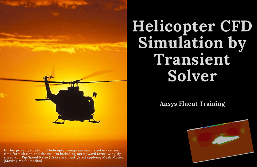
In this project, the rotation of helicopter wings is simulated in transient time formulation. The results, including net upward force, wing tip speed, and Tip Speed Ratio (TSR), are investigated by ANSYS Fluent software. We perform this CFD project and investigate it by CFD analysis.
The present model is designed in three dimensions using Design Modeler software. The geometry for analyzing this simulation consists of a room and a balcony. The meshing of the model has been done using ANSYS Meshing software. The element number is 937677.
Methodology
To generate upward movement in aerodynamic applications, movement of a certain amount of air in the downward direction is needed, generating upward motion. For helicopters, this air movement is done using a propeller consisting of 2 or more wing-shaped geometries rotating around a center.
The propeller is aerodynamically designed to force air to flow over it and increase the air pressure under the wing. In this simulation, the propeller rotates with an angular velocity equal to 1250 rpm in the Y direction.
The Mesh Motion option simulates the rotating motion of helicopter blades. Moreover, the RNG k-epsilon model is exploited to solve turbulent fluid equations.
Conclusion
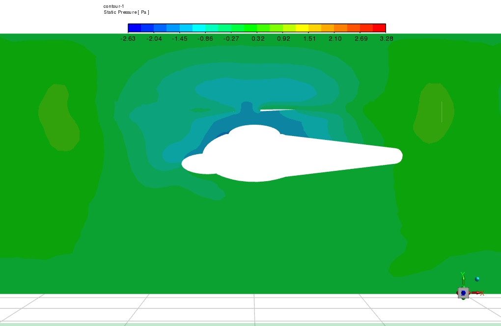
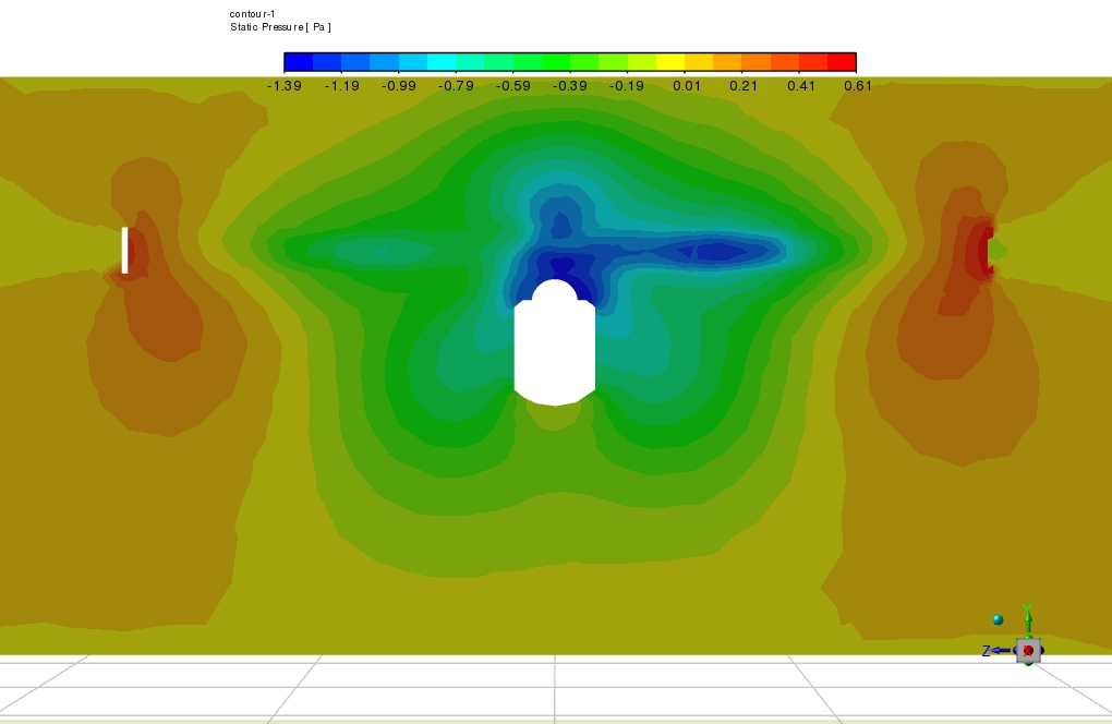
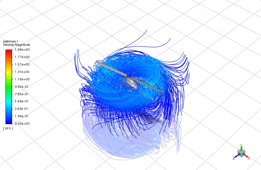
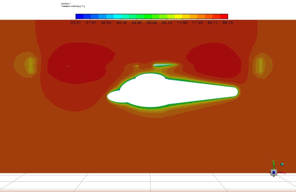
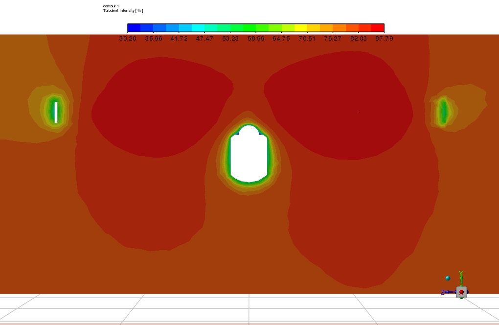
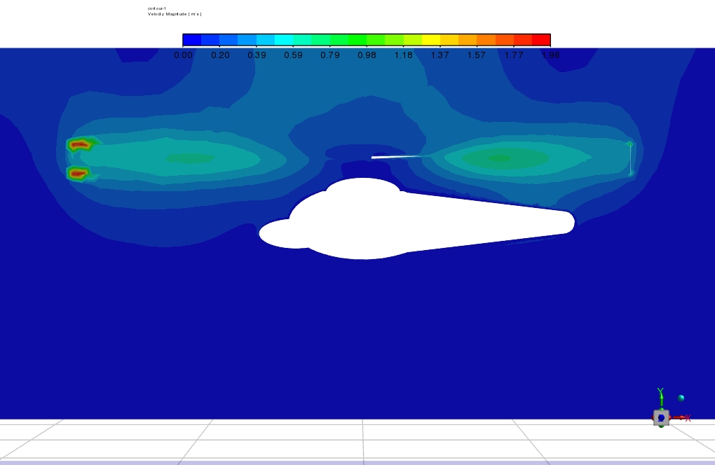
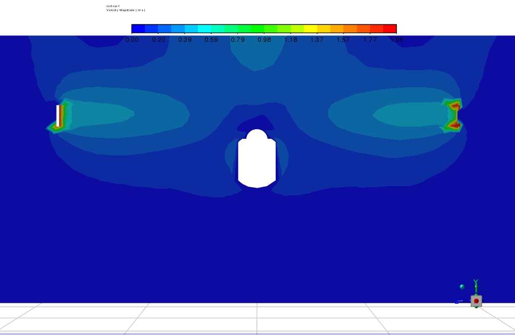
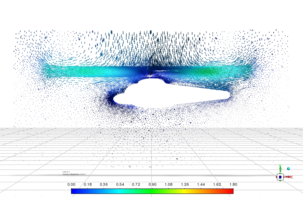
At the end of the solution process, two-dimensional contours related to the velocity, pressure, turbulent viscosity, and streamlines are obtained. As in streamlines, the helicopter blades’ rotation also caused a rotating motion inside the air.
Also, based on the calculations performed in the software, the Pressure difference between under and over the helicopter geometry equals 5 Pa. Maximum air velocity in the domain is equal to 2 m/s. Air velocity at the wing tip, which has the maximum velocity magnitude on the wing length, is equal to 1.96 m/s.

Xzavier Nitzsche V –
Can this simulation be used to optimize the design of a helicopter?
MR CFD Support –
Absolutely! The simulation provides detailed insights into the flow behavior and aerodynamic forces on the helicopter, which can be used to optimize the helicopter design for improved performance.
Isadore Dibbert –
How does the simulation handle the boundary layer on the helicopter’s surface?
MR CFD Support –
The simulation uses wall functions to accurately model the boundary layer on the helicopter’s surface. This ensures an accurate prediction of the flow behavior near the helicopter’s surface and the resulting aerodynamic forces.
Prof. Alphonso Osinski Jr. –
Can this simulation model the effects of different flight conditions on the helicopter’s performance?
MR CFD Support –
Yes, the simulation can be adjusted to model different flight conditions, such as forward flight, hover, and descent. This allows for a comprehensive analysis of helicopter performance under various operating conditions.