Hydro-Kinetic Turbine, Cavitation study CFD Simulation, Ansys Fluent
$200.00 $100.00 Student Discount
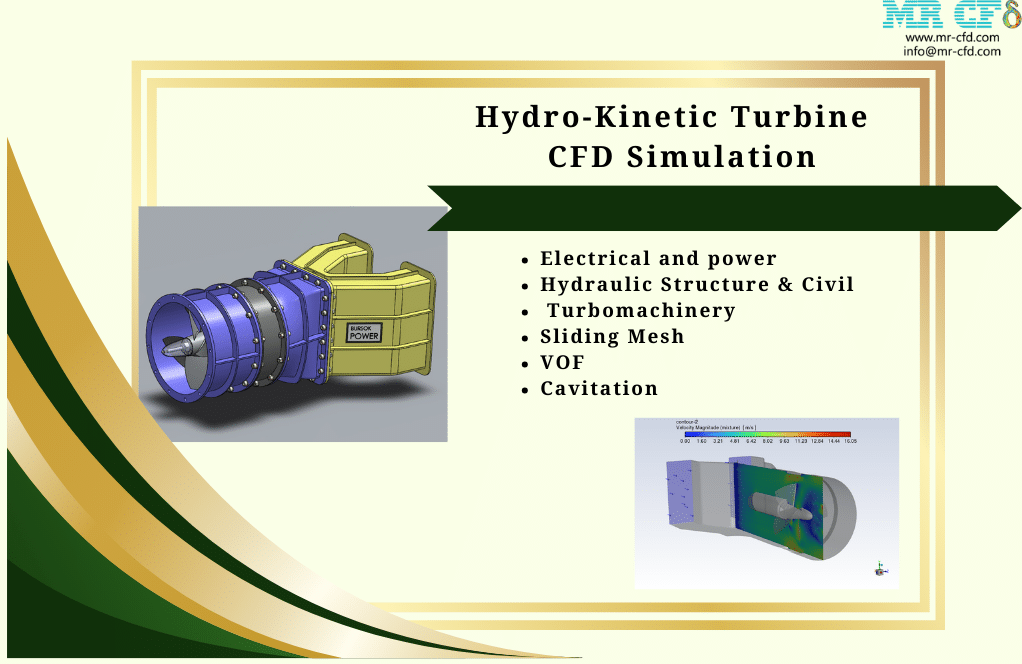
- The problem numerically simulates Hydro-Kinetic turbine using ANSYS Fluent software.
- We design the 3-D model with the Solidworks software.
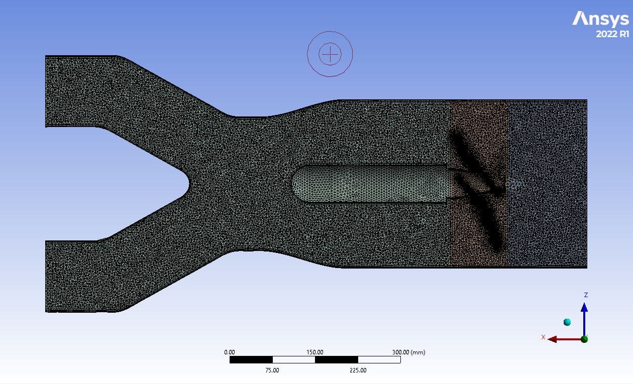
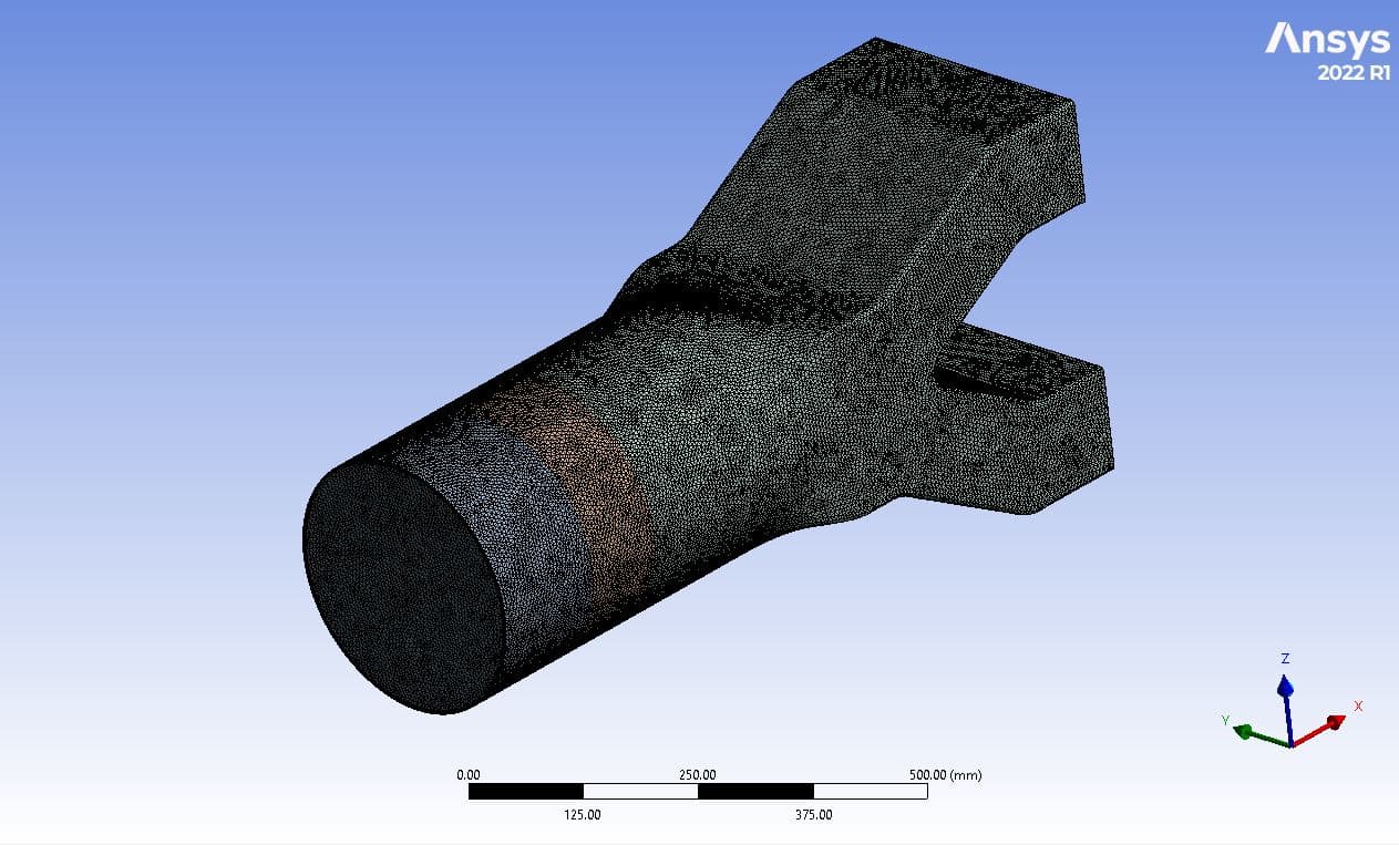
- We mesh the model with ANSYS Meshing software, and the element number equals 7,758,370.
- The Mesh Motion (Sliding Mesh) technique is used to simulate the rotation of the turbine blades
- The VOF method is used In this simulation.
To Order Your Project or benefit from a CFD consultation, contact our experts via email (info@mr-cfd.com), online support tab, or WhatsApp at +44 7443 197273.
There are some Free Products to check our service quality.
If you want the training video in another language instead of English, ask it via info@mr-cfd.com after you buy the product.
Description
Description
The project at hand involves the simulation of a Hydro-Kinetic turbine utilizing the powerful capabilities of ANSYS Fluent software. The water, flowing at a velocity of 5 m.s-1, passes through the water turbine, driving it to produce energy. The Hydro-Kinetic turbine is a device that converts the kinetic energy of water into electrical energy, making it an excellent source of renewable energy.
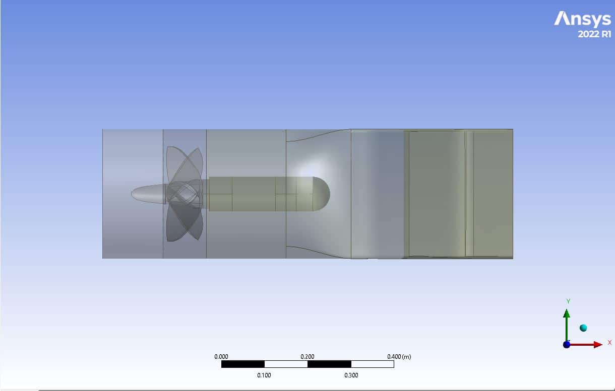
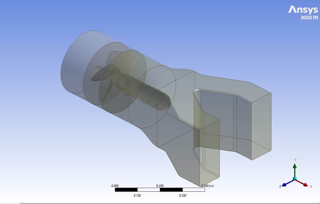
To design the present model, a three-dimensional approach is employed. The blades are meticulously drawn in SOLIDWORKS software at a specific angle and distance from the central axis, after which they are imported into the Design Modeler software to create an integrated blade design. In the space surrounding the turbine blades, a special cylinder is created to make the water flow in a continuous circular motion. In contrast, a rectangular cube space is designed to allow for free water flow.
The meshing of the model was done through ANSYS Meshing software using an unstructured mesh type to ensure maximum flexibility and accuracy. The method used to increase the meshing accuracy is Tetrahedrons, and the element number is 7,758,370.
Methodology
The Mesh Motion (Sliding Mesh) technique is used to simulate the rotation of the turbine blades. Therefore, for the cylindrical region, the mesh mode is defined by defining a rotational speed of 60 rpm around the central horizontal axis of the turbine. The VOF method is used In this simulation.
On top of the mentioned activated models, the standard k-epsilon model is used to solve the turbulent fluid equations. The present study is performed in transient format and 3D. Moreover, the simulation takes into account the effects of gravity in the Y direction, with a magnitude of -9.81 meters per second squared.
Conclusion
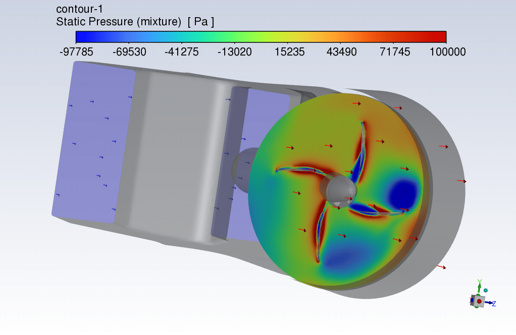
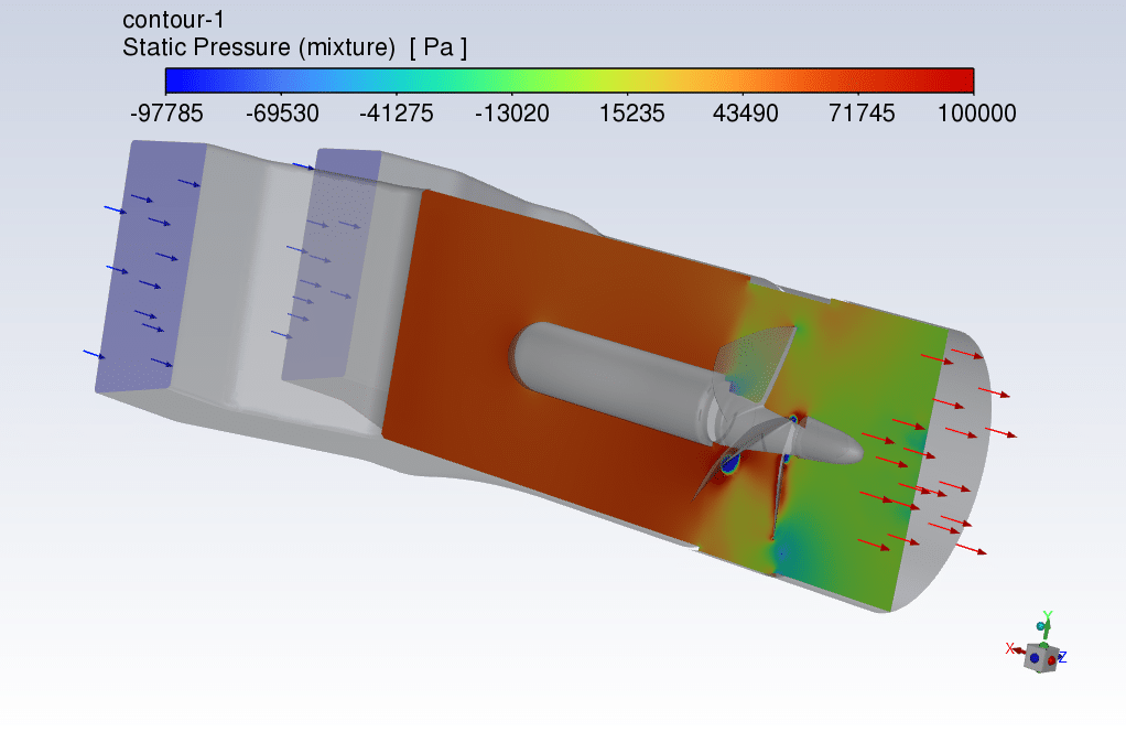
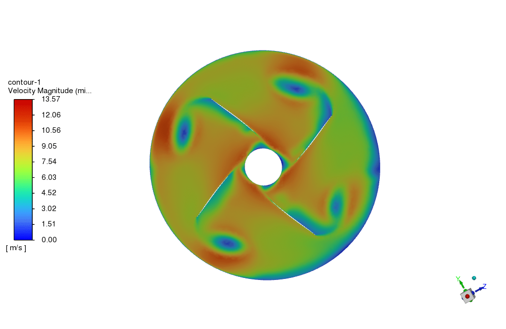
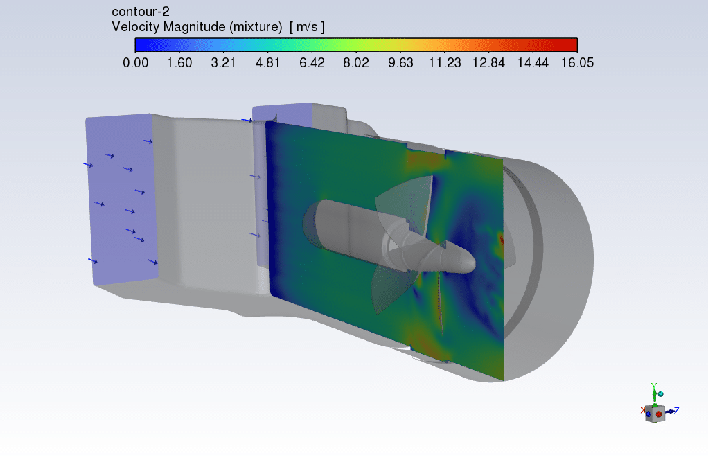
At the conclusion of the solution process, contours in both two and three dimensions are obtained that relate to pressure, velocity, path lines, and velocity vectors. The highest velocity occurs in close proximity to the blades in rotation. Additionally, all potential outcomes can be extracted, such as the pressure drop equaling 2.9811e+4.
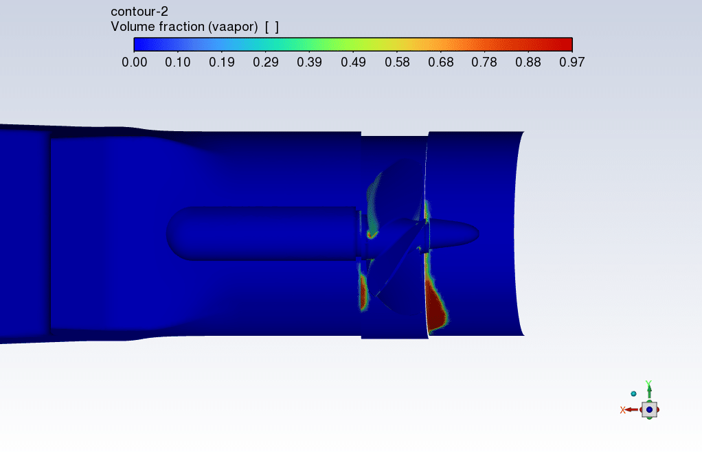
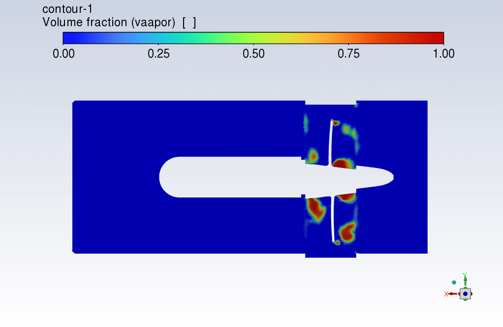
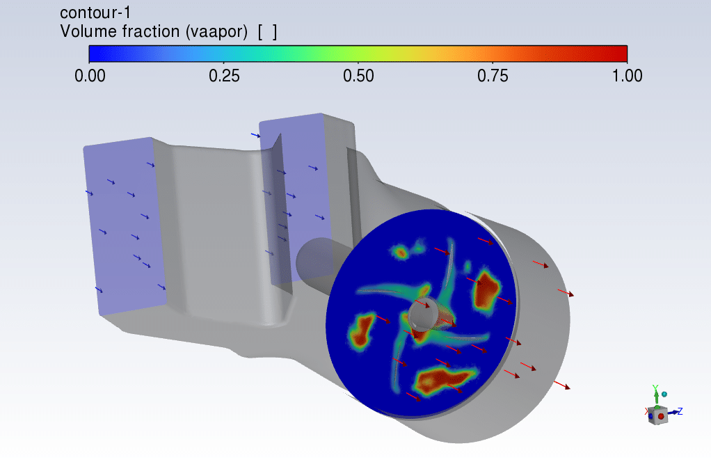
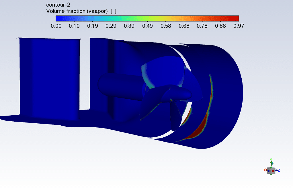
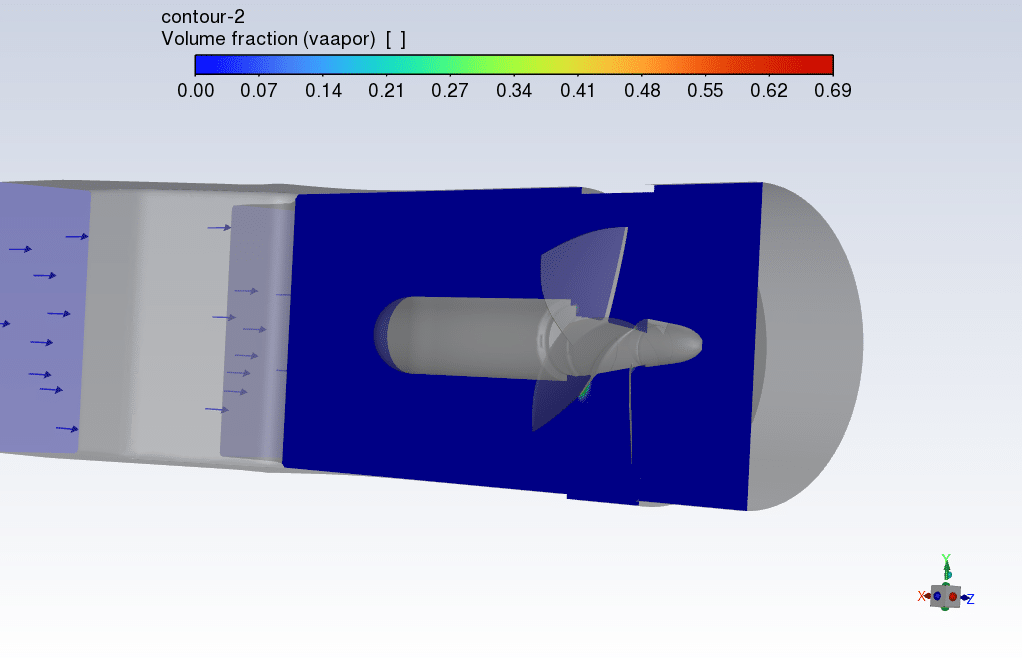
Cavitation is a phenomenon in which the static pressure of a liquid drops below the vapor pressure of the liquid, leading to the formation of small voids filled with vapor in the liquid. Vapor volume fraction Contours show where the cavitation happened.



Rosemarie Skiles Jr. –
I was wondering if the cavitation could affect the performance and longevity of the hydro-kinetic turbine, how is this issue addressed in the simulation?
MR CFD Support –
In the simulation, the cavitation effects are evaluated by monitoring the vapor volume fraction. We ensure that the design of the turbine minimizes these cavitation zones, as they can erode the material and decrease efficiency. Through the CFD analysis, we can modify the turbine’s characteristics or operating conditions to address any performance concerns that arise due to cavitation.
Emelie Abernathy III –
I’m really impressed with the detail in the Hydro-Kinetic Turbine simulation. But can you please explain how cavitation impact the turbine’s performance in terms of efficiency?
MR CFD Support –
Cavitation can negatively affect the performance and efficiency of a Hydro-Kinetic turbine by introducing irregular fluid flow patterns and causing vibrations, noise, and potential damage to the turbine blades. The presence of cavitated regions also causes a loss of effective blade surface and alters the flow dynamics, leading to reduced energy conversion efficiency. It’s essential to consider cavitation during the design and operation to maintain high efficiency and prolong the turbine’s lifespan.
Loma Skiles DDS –
I’m fascinated by the detailed analysis of the cavitation effects on the turbine blades. Could you clarify if the study also includes predictions of the potential wear on the blades due to cavitation over an extended period of operation, or does it merely illustrate the cavitation occurrence around the blades?
MR CFD Support –
To determine the potential wear on the turbine blades due to cavitation, we usually run an extended simulation over the lifespan of the turbine blades. This analysis measures the duration and intensity of cavitation incidents to provide an estimate of the material erosion rate and the consequent reduction in blade lifespan. Unfortunately, as the customer’s review didn’t mention such an extended analysis but instead focused on the occurrence of cavitation, we can’t confirm whether this study included those wear predictions. We assume that this review highlights the ability to visualize and investigate cavitation occurrences, but we’d be eager to conduct further studies if wear prediction is of interest.
Selmer Walsh III –
The tutorial sounds thorough, but I’d like to understand more about how cavitation is specifically modeled in ANSYS Fluent for this project. Can you clarify that?
MR CFD Support –
Absolutely! In ANSYS Fluent, cavitation is modeled using a cavitation model that takes into account the liquid’s properties, such as its vapor pressure, to determine when and where cavitation will occur. In the case of the Hydro-Kinetic turbine study, typically, a cavitation model, such as the Singhal or Zwart-Gerber-Belamri model, is used coupled with a multiphase VOF (Volume of Fluid) model, since the phenomenon involves the transition between liquid and vapor phases. The settings for the model would be configured based on the fluid’s operational environment such as pressure, temperature, and fluid properties to predict the formation of vapor bubbles and their dynamics as they move through the turbine’s flow field.
Bradley Bins –
I loved the detailed explanation of the process and the visualization aids in the conclusion. It really helped me grasp the complexities of cavitation in Hydro-Kinetic turbines.
MR CFD Support –
Thank you for your positive feedback! We’re thrilled to hear that our simulation’s explanation and visual aids were effective in increasing your understanding of cavitation effects in Hydro-Kinetic turbines. If you have any more questions or need further information, feel free to ask.
Shana Stroman –
What is the primary purpose of using standard k-epsilon turbulence model in this simulation?
MR CFD Support –
The standard k-epsilon model is employed in the simulation as it provides a reliable numerical approach for solving turbulent flows. It helps in predicting the turbulent kinetic energy (k) and its rate of dissipation (epsilon), which are critical for accurately calculating complex flow patterns around the turbine blades in regimes with moderate to high Reynolds numbers. This information is vital in optimizing turbine efficiency and predicting performance.
Dr. Tre Baumbach –
I was truly impressed with how comprehensive the study of the Hydro-Kinetic turbine was in simulating real-world water flow and energy production. It is refreshing to see such sophisticated and detailed analysis in converting kinetic energy to electrical energy using renewable sources.
MR CFD Support –
Thank you for your positive feedback! We’re thrilled to hear that the study was informative and impressive. It’s our goal to provide detailed analyses that reflect real-world scenarios, and we appreciate your recognition of the effort put into this simulation. Thank you for choosing our products for your learning and research needs!
Miss Wilma Mertz II –
I’m really impressed by the detailed cavitation study and simulation of the hydro-kinetic turbine. The use of a 3D approach and the high element meshing for accuracy demonstrate a rigorous approach to understanding the complex dynamics involved.
MR CFD Support –
Thank you for your positive feedback! We’re thrilled to hear that the attention to detail and comprehensive approach in our hydro-kinetic turbine simulation was impressive. We strive to ensure our simulations provide an accurate and in-depth understanding of fluid dynamics and the phenomena at play. We appreciate your review!
Garrison Jerde –
The explanation of cavitation is great! Really makes you appreciate the level of detail in the simulation.
MR CFD Support –
Thank you for your positive feedback! We’re thrilled to hear that the explanation of cavitation helped in deepening your understanding of the simulation. If you need more information or further assistance, feel free to reach out!
Diamond Breitenberg –
The simulation description is very thorough. I am excited by the idea of harnessing renewable energy. I imagine the final outcomes allowed for analysis of efficient blade design for maximum energy production.
MR CFD Support –
Thank you for your kind words! We are glad that the simulation resonated with your passion for renewable energy. Indeed, the outcomes allow for a detailed analysis of the blade design, enabling the pursuit of highly efficient energy production. We value your enthusiasm and support for sustainable solutions.
Maureen Ryan –
Can this simulation also calculate the efficiency of the Hydro-Kinetic turbine?
MR CFD Support –
Regarding the calculation of the turbine’s efficiency, ANSYS Fluent is capable of evaluating the performance of the turbine, including its efficiency, by analyzing the power output against the flow conditions. Efficiency calculations would include considering power generated against the kinematic energy coming into the system.
Francesco Koepp –
The simulation process described for the Hydro-Kinetic turbine is comprehensive. Great to see an emphasis on the effect of cavitation on the turbine’s performance. The contours provided must give valuable insights into the fluid dynamics involved in renewable energy applications.
MR CFD Support –
Thank you for your positive review! We’re pleased to hear you found the simulation process comprehensive and insightful, especially regarding the effects of cavitation, which is indeed a critical aspect of hydro-turbine performance analysis. If you have further inquiries or need more intricate details on the project, feel free to reach out. We’re always here to support your interest in CFD applications for renewable energy.
Ms. Judy Windler –
I’m interested in how the simulation handles the transition from non-cavitating to cavitating conditions at the blades. Can the model account for different stages of cavitation accurately?
MR CFD Support –
The simulation utilizes the VOF method, combined with the physical properties of water and vapor, to accurately model the phases and transition between non-cavitating and cavitating conditions. Depending on fluid pressure and temperature, the software automatically calculates the vapor pressure and facilitates the tracking of phase transition near the blades, thus enabling the simulation of different stages of cavitation with precision.
Alda Yundt MD –
I’ve finished my project on Hydro-Kinetic turbines. The contours were exceptional! Seems like cavitation is well-presented. What aspect of the flow around the blades is most affected by cavitation?
MR CFD Support –
Thank you for your kind words on the project! In the flow around the blades of a Hydro-Kinetic turbine, cavitation most significantly affects areas of low pressure where the velocity is the highest due to changes in the blade geometry. It often occurs near the trailing edge of the blades or in regions where the flow accelerates significantly around the blade surface. Cavitation can lead to pitting and erosion over time, which is important to monitor for maintenance and efficiency.
Mr. Rasheed Hill I –
In the Hydro-Kinetic turbine simulation, were the effects of cavitation on turbine performance examined or calculated in any specific manner?
MR CFD Support –
The simulation includes an examination of the effects of cavitation on turbine performance by analyzing Vapor Volume Fraction Contours, which provide visual representation and location of where cavitation occurs within the flow. The presence and extent of cavitation can impact turbine durability and efficiency, and it is a key aspect that has been studied within this simulation using ANSYS Fluent.
Dr. Shanel Larkin –
As an energy engineer, I found the detail on the Hydro-Kinetic turbine simulation fascinating. It’s clear that comprehensive modeling was involved, especially the use of a Sliding Mesh for blade rotation and the attention to cavitation effects. This information will be invaluable for my own renewable energy projects!
MR CFD Support –
Thank you so much for your kind words! We’re thrilled to hear that our Hydro-Kinetic turbine simulation is providing valuable insights for your renewable energy projects. If there’s anything more we can assist with or clarify, don’t hesitate to get in touch with us.
Prof. Van Harvey –
The tutorial was fantastic! I had never quite grasped CFD simulation for cavitation studies until I used your Hydro-Kinetic Turbine simulation guide. Seeing the vapor volume fraction contours come to life was so insightful.
MR CFD Support –
Thank you for your kind words! We’re thrilled to hear that our Hydro-Kinetic Turbine simulation guide was helpful and gave you greater insight into cavitation studies. We strive to create high-quality learning materials that make complex concepts more approachable. Your feedback is highly appreciated!
Evans Auer –
The description mentions the use of the standard k-epsilon model for turbulent flow. Could you explain why this model is preferred over others for this particular simulation?
MR CFD Support –
The standard k-epsilon model is chosen for its robustness and accuracy in simulating turbulent flows, especially in complex geometries like a rotating turbine. This model efficiently predicts the average flow characteristics which are crucial in determining the performance of the Hydro-Kinetic turbine under different operating conditions.