ICU Ventilation Design Improvement, Industrial Application
$300.00 $150.00 Student Discount
- The geometry is designed in Design Modeler & meshed in ANSYS Meshing software.
- One of the patients suffering from respiratory disease. It is one of our goals to prevent it from dispersion.
- The one-way discrete Phase Model (DPM) is used to model aerosols.
- An acceptable thermal comfort is our other concern in this project which is controlled by PPD & PMV factors.
Click on Add To Cart and obtain the Geometry file, Mesh file, and a Comprehensive ANSYS Fluent Training Video.
To Order Your Project or benefit from a CFD consultation, contact our experts via email (info@mr-cfd.com), online support tab, or WhatsApp at +44 7443 197273.
There are some Free Products to check our service quality.
If you want the training video in another language instead of English, ask it via info@mr-cfd.com after you buy the product.
Description
ICU Design Improvement Considering Preventing Respiratory Disease Transmission & Thermal Comfort
Introduction:
Almost all infectious respiratory diseases are spread from person to person, which means that anyone in a school, workplace, community, etc can contract one.In the ICU room, the situation of breathing diseases is strongly crucial and may result in hard physical damage.This is why we seek a smart design to prevent any transmission while providing the best HVAC (thermal comfort) conditions.
This product is the 6th chapter of the DPM training course.
Project Description:
In this project, we set the target to design an ICU considering thermal comfort conditions including PMV & PPD. Also, It is important to prevent the transmission of infectious diseases. In the project, one patient called patient #1 is suffering from a respiratory disease which puts an infection scenario in more attention.
We aim to keep mentioned parameters within the acceptable range shown in the table:
In the following, the design of the ICU will be explained in detail.
- Step 1: (Widely used HVAC system)
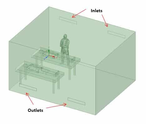
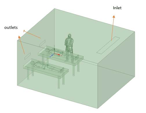
In the first step, the ICU is simulated with its initial condition considering the widely used HVAC systems which assume inlets and outlets on opposite walls(check Figure below). The inlet velocity is 0.58m/s and 294K temperature while virus aerosols are injected with patient 1 breath.
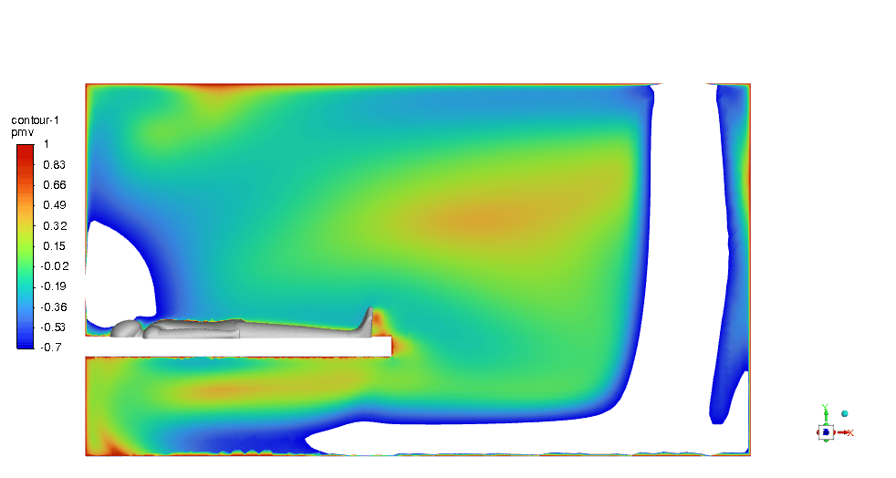
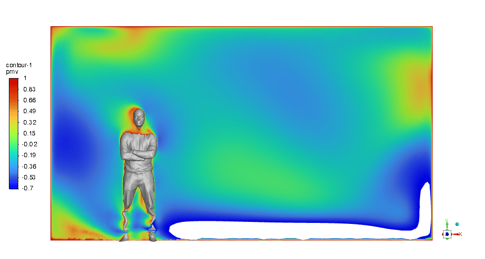
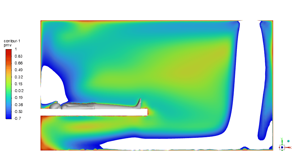
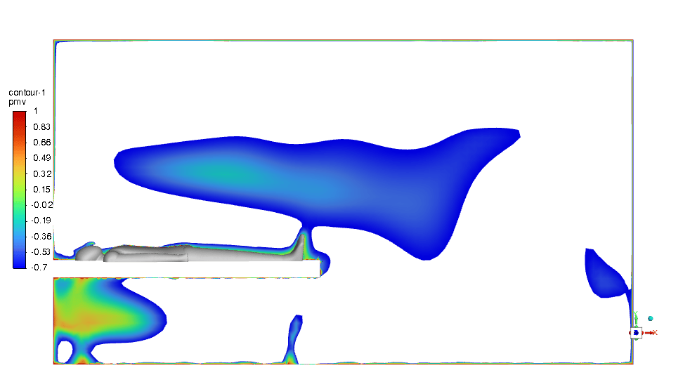
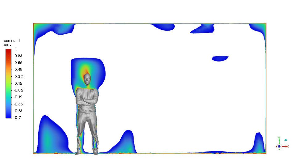
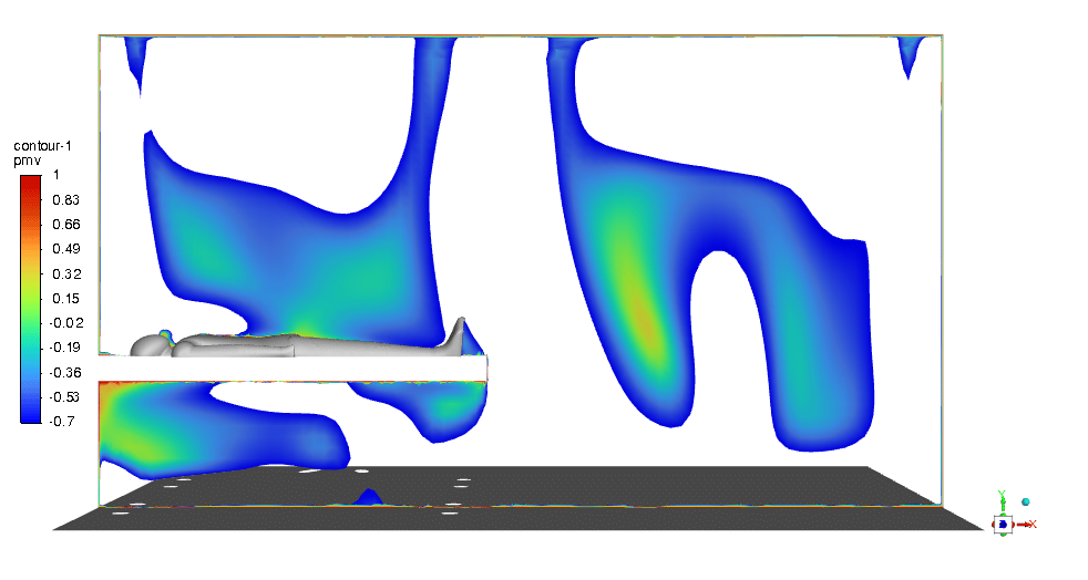
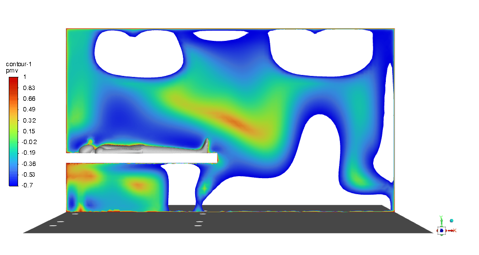
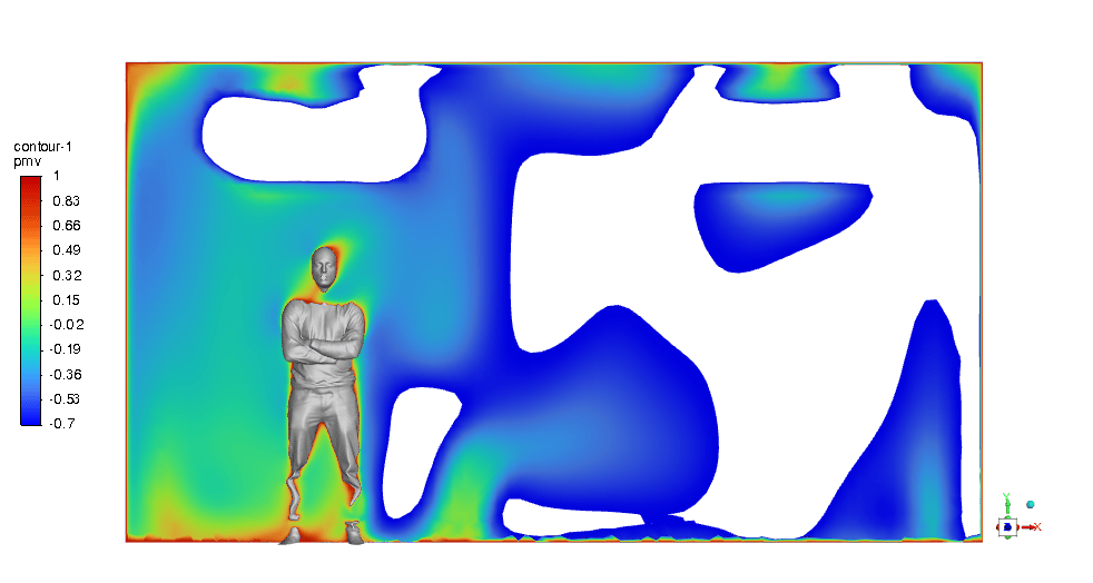
The results of the simulation show how the designed HVAC system could provide acceptable PMV but not PPD. As depicted in figure 3, the PMV contours around the doctor and the patients within the -0.7 to 1 range prove the claim.
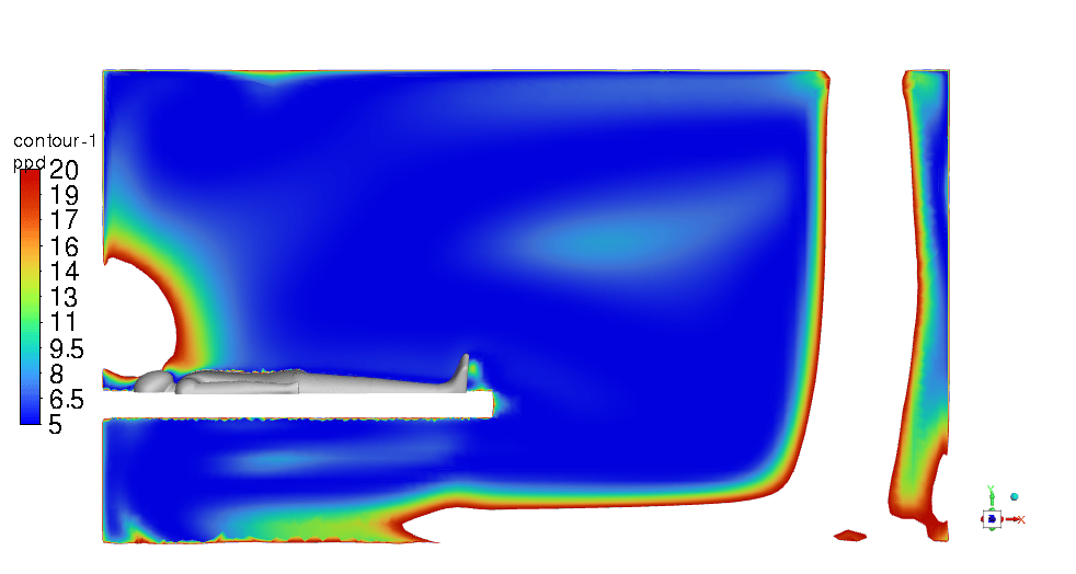
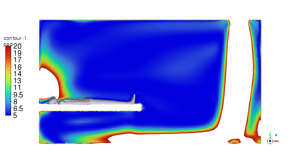
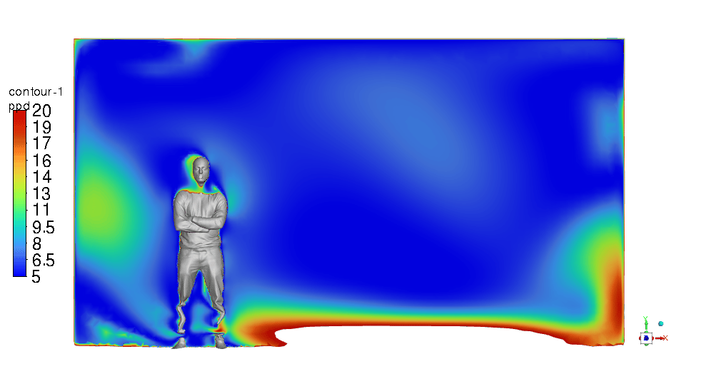
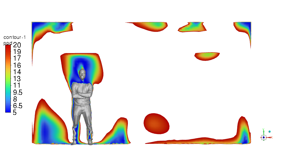
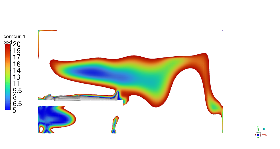
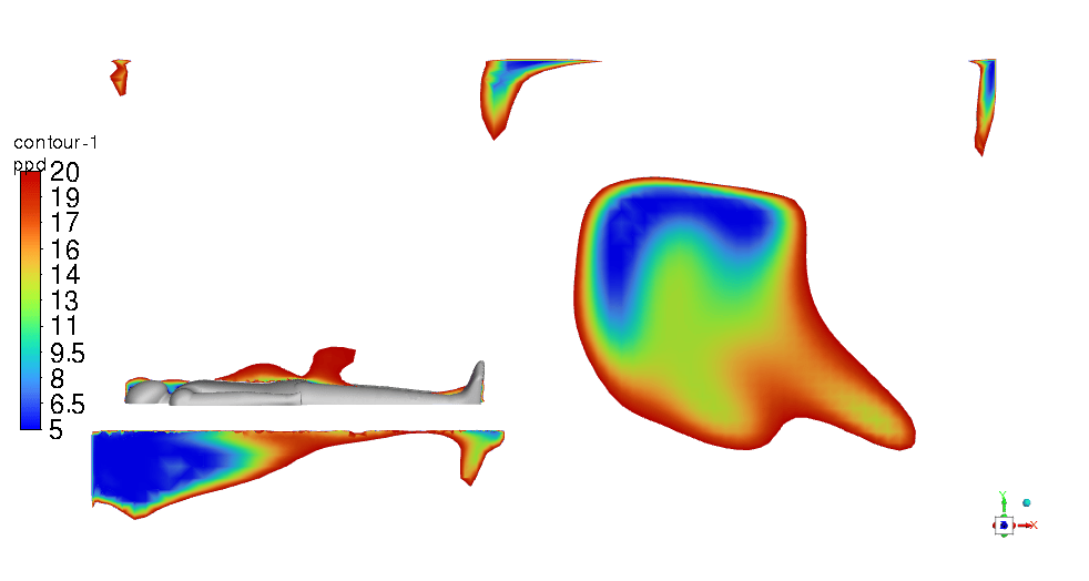
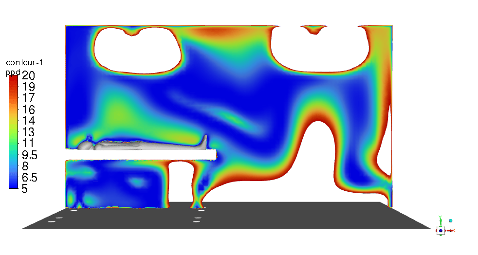
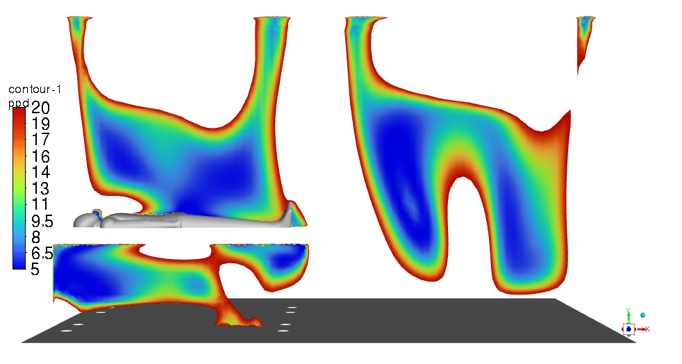
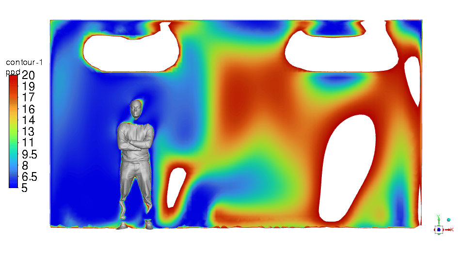
Moreover, figure 4 illustrates the PPD in the range of 5% to 20%, and obviously, it is not satisfying for an ICU room thermal comfort.
Figure 3- PMV contour a) around the doctor b) around patient #1 c) around patient #2
Figure 4- PPD contour a) around the doctor b) around patient #1 c) around patient #2
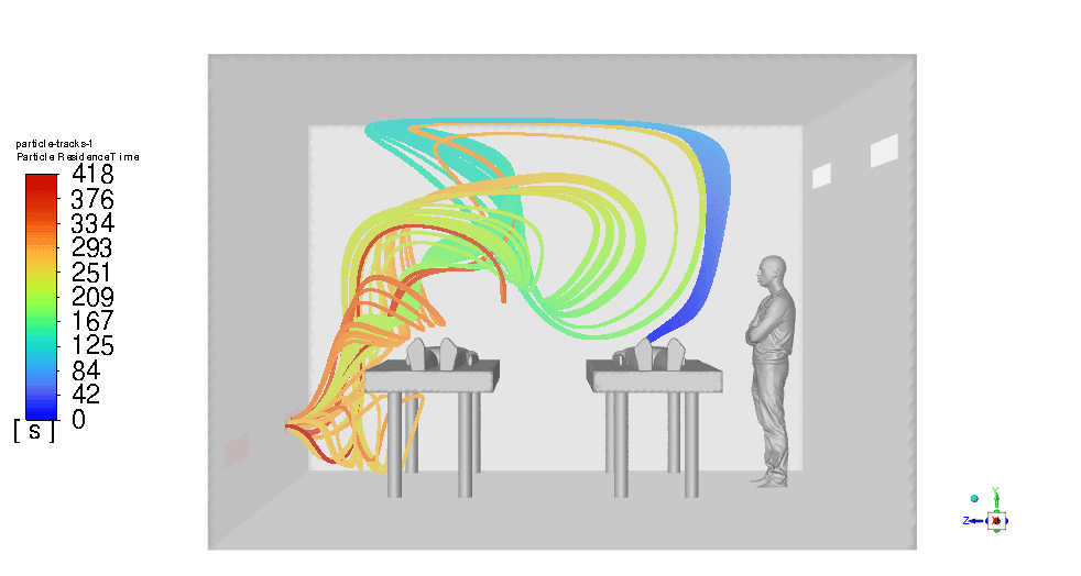
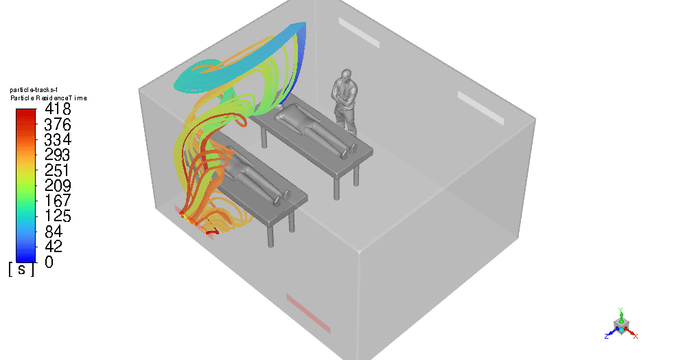
On the other hand, it lasts about 7 minutes for the virus particles to escape the room completely which is not satisfying at all! (figure 5) It is highly probable to be spread to the doctor and the other patient.
Figure 5- Virus Particles Residence Time a) Isometric view b) Front view
- Step 2: (Using Cross Ventilation)
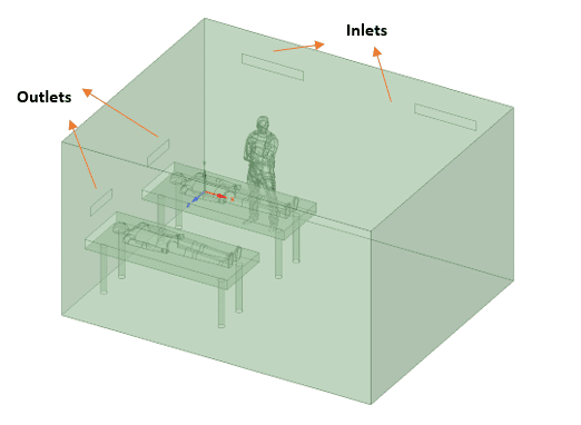
In the second step, the outlets are proposed to be installed above the head of the patients but keep the inlets where they were.
We predict to decrease in the virus particle`s residence time by cutting its distance to the outlets short. Design 2 is modeled and shown below:
Figure 6- Design 2 geometry
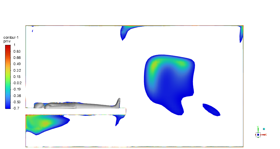
Just like the previous step, first of all, we need to check the thermal condition. As illustrated in Figures 7 & 8, the PMV and PPD with values in the acceptable range are hardly visible and most of the room is not in an appropriate thermal condition.
Therefore, Although we expected to reduce the particles’ residence time (which will be determined in the following), the thermal comfort condition became poor in contrast with the previous design.
Figure 7- PMV contour a) around the doctor b) around patient #1 c) around patient #2
Figure 8- PPD contour a) around the doctor b) around patient #1 c) around patient #2
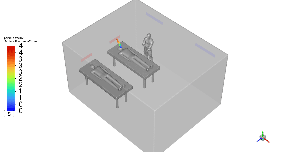
By the way, figure 9 proves that our theory and expectations of reducing aerosol particles’ residence time have come true. It reaches just 4 seconds which is a big step in the designing process, still.
Figure 9- Virus Particles Residence time
- Step 3: (Revision to Design2)
The cross-ventilation design (design #2) has proved that by using outlet vents above the head of the patients, the risk of infection gets to nearly 0%!
for the patients suffering from respiratory disease. Hence, we came up with the idea of keeping the outlets but changing the inlet`s (supply) locations.
Also, a decrease in the velocity of inlet vents could be effective to provide the appropriate thermal condition. This is called Design #3 shown below:
Figure 10- Design 3 geometry
Instead of using two 150*300mm, a single 300*600 inlet vent is used on the ceiling, away from the beds. Also, the reduction in velocity of the inlet is employed (0.15m/s).
The PMV & PPD contours show that this design can be very promising and we can be assured of thermal comfort in the ICU room. Most of the critical regions in the room are in an acceptable range. You can check them below in Figures 11 & 12.
Figure 11- PMV contour a) around the doctor b) around patient #1 c) around patient #2
Figure 12- PPD contour a) around the doctor b) around patient #1 c) around patient #2
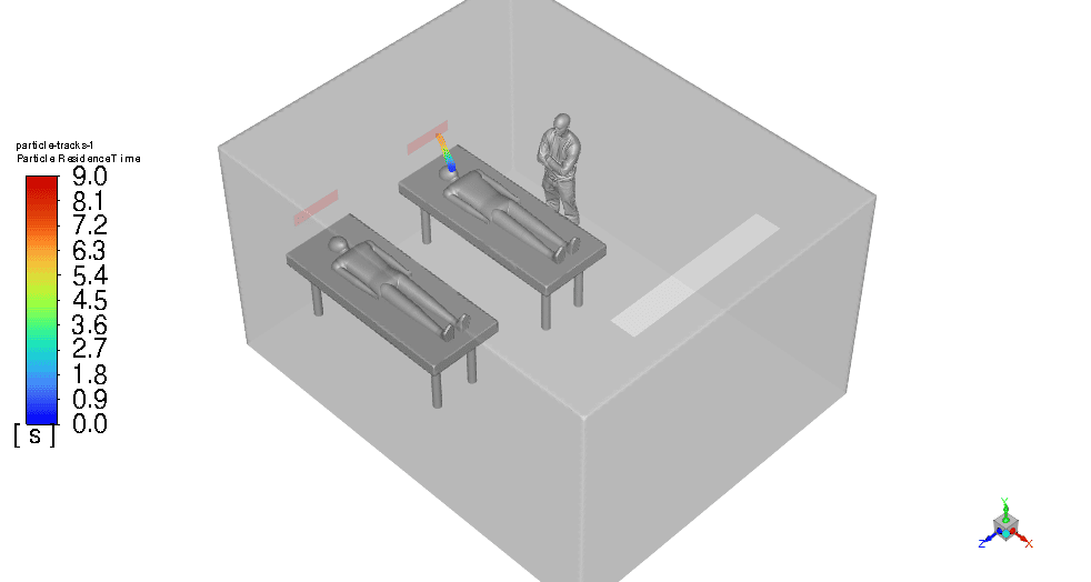
From another aspect, the aerosol particle’s residence time increases up to 9 seconds in contrast with Design 2 which was 4s. Although it gets doubled, still is effective and can prevent any dispersion.
Figure 13- Virus Particles Residence time
So we can sum up the results in the table below:






Junior Gottlieb –
I’m impressed by the stepwise improvement in the ventilation design to prevent disease transmission in the ICU scenario simulated. Could you clarify whether the changes made in Design #3 affect the air circulation pattern in a way that might indirectly influence pathogen spread, aside from the direct benefits of reduced aerosol residence time?
MR CFD Support –
Thank you for your kind words! Yes, changes in Design #3, including adjusting the inlet location and velocity, affect air circulation patterns. These alterations contribute to an indirect reduction of pathogen spread by ensuring that the infectious aerosols are effectively captured by the airflow and directed towards the filtration system quickly, reducing the likelihood of the aerosols remaining in the vicinity of individuals within the ICU.
Gladyce Dickinson –
Does this improved ICU design also take into account minimizing noise pollution from the HVAC system? I know maintaining a quiet environment is critical for patient recovery.
MR CFD Support –
Admin Response: Thank you for your question. The simulation project primarily focuses on reducing the transmission of infectious diseases and ensuring proper thermal comfort through HVAC design. While our report does not specifically detail noise pollution measures, typically in actual design implementations, considerations for noise reduction like selecting low-noise HVAC components and implementing acoustic treatments would be important to ensure a comprehensive solution for patient recovery environments like the ICU.
Wyatt Roob –
This is an incredibly thoughtful and comprehensive approach to ICU design! Not only does it address thermal comfort but also prioritizes the prevention of disease transmission. Bravo to the MR CFD Company for their detailed simulations and innovative engineering solutions. It’s clear a significant amount of research and expertise was involved in achieving such results.
MR CFD Support –
Thank you very much for your kind words and recognition of the work that went into the ICU ventilation design improvement project. It is our main goal to provide products that are not only effective but also contribute positively to public health and safety. We’re delighted to hear you found our approach comprehensive and innovative. Your encouragement inspires us to keep pushing the boundaries of what’s possible in the field of CFD.
Vella Beer Sr. –
Does design 3 ensure both proper thermal comfort and effective airborne disease control? And, how do you guarantee it satisfies both?
MR CFD Support –
Design #3 has shown promising results in fulfilling both thermal comfort and infection control requirements, as indicated by within-range PMV and PPD contours and a reduced aerosol particle residence time. The PMV and PPD ranges indicate an acceptable level of thermal comfort, while the particle residence time indicates a low risk of disease spread, even though it is slightly higher than in Design #2. These parameters must be rigorously validated through empirical testing and with reference to health and safety guidelines to ensure they are truly effective in a real-world setting.
Mrs. Vergie Rath I –
In the ICU ventilation design project, have filter systems or air purifiers been included as part of infectious disease control, or is the design relying solely on maximizing airflow and ventilation systems to prevent transmission?
MR CFD Support –
In the project described, there is no direct mention of filter systems or air purifiers being used for infectious disease control. The focus seems to be on optimizing the design of the ventilation system, specifically the positioning and strength of inlets and outlets, to manage PMV and PPD for thermal comfort, while reducing the residence time of virus aerosols to help prevent disease transmission. Air purifier or filtration mechanisms may be considered in a complementary role to the HVAC adjustments but are not outlined in this portion of the project description.
Elsa Macejkovic –
The analysis of the PMV and PPD conditions is crucial for ensuring thermal comfort. Could you shed more light on the relationship between patients’ thermal comfort and the spread of virus particles as the inlet velocity changes?
MR CFD Support –
In the simulation of ICU Ventilation Design Improvement, the PMV (Predicted Mean Vote) and PPD (Predicted Percentage of Dissatisfied) were studied along with the residence time of virus particles to achieve both thermal comfort for patients and prevent disease transmission. Changes in inlet air velocity can affect the distribution of temperature and air flow patterns, impacting PMV and PPD ratings as well as the dispersion and clearance of airborne particles, such as viruses. Lowering the inlet velocity could reduce disruptive air flows that might spread virus particles but may also create hot or cold spots that impact thermal comfort, illustrated by PMV and PPD contours. The goal is to find a balance where inlet velocity maintains adequate air mixing for comfort without contributing to undesirable particle spread.
Yasmeen Reichel –
Could you explain how the aerosol particles’ residence time was accurately measured to ensure the design’s effectiveness in infection control?
MR CFD Support –
To measure the aerosol particles’ residence time accurately in the simulation, particle tracking techniques are used within the CFD software. The simulations track the movement and concentration of aerosol particles emitted from patient #1’s breath over time. By defining particle release parameters that replicate a cough or a sneeze and setting up transient simulations, the software can track the time these particles take to be removed from the ICU room through the ventilation system. The modeling accounted for various factors such as airflow patterns, particle size, and room configurations to ensure realistic and accurate results that underpin the effectiveness of the design.
Louisa Weimann –
Could thermal discomfort lead to any additional health risks for ICU patients?
MR CFD Support –
Thermal discomfort in an ICU can lead to non-thermal comfort conditions which may affect patient recovery by causing stress, impacting sleep quality, and potentially reducing resistance to infections.
Prof. Gabrielle Schuppe PhD –
The ICU Ventilation Design Improvement project simulation seems fascinating. How was the virus particle dispersion modeled, and which type of respiratory aerosols were used in the simulation for the representation of virus particles?
MR CFD Support –
In this simulation, virus particle dispersion is modeled by tracking the virus aerosols as they are expelled from patient #1 during breathing or coughing. The aerosols are introduced into the air flow in the vicinity of the patient, simulating the spread of infectious particles. For the representation of the virus particles, a standard respiratory aerosol range is likely used, informed by the size and behavior of common respiratory disease particles like influenza or the novel coronavirus. Diligent computational fluid dynamics (CFD) methods enable observation of the aerosol motion and interaction with the surrounding airflow, assisting in designing effective prevention measures for disease transmission in an ICU environment.
Laron Fadel Sr. –
The simulations were informative, thank you. Is design #3 currently the best option per your data, considering both safety and comfort for a real ICU environment?
MR CFD Support –
Based on the data presented from the simulations, design #3 indeed strikes an effective balance between safety from infection transmission and thermal comfort in the ICU environment. The virus particles’ residence time is reasonably low at approximately 9 seconds, which minimizes the chance of disease spread, while the PMV and PPD contours indicate that thermal comfort is successfully attained in critical areas.
Tiffany Quigley –
I’m curious about the change in velocity for inlet vents from Design 2 to Design 3. Why was the velocity reduced, and how did it help in achieving the desired PMV and PPD conditions?
MR CFD Support –
The velocity of the inlet vents in Design 3 was reduced to minimize air turbulence and to ensure a more gentle distribution of air within the ICU. This lower velocity aids in avoiding drafts that could cause discomfort, thus helping in achieving PMV and PPD conditions that contribute to a thermally comfortable environment for the patients and staff. The trade-off was a slight increase in aerosol particle residence time, but it still maintained effectiveness in infection prevention, balancing both thermal comfort and disease transmission mitigation effectively.
Noemi Cruickshank –
I’m really interested in the influences of the different types of supply vents on the thermal comfort within the ICU. Does your study explore different shapes or sizes of vents, aside from their location and velocity?
MR CFD Support –
Yes, our study does explore different variables for the supply vents. We adjust shapes, sizes, and even the number of vents, alongside their specific orientations, locations, and velocities. These adjustments are all part of our efforts to achieve optimal thermal comfort without compromising infection control standards.
Miss Lindsay Leffler –
What kind of numerical model is applied to predict PMV and PPD in the ICU room?
MR CFD Support –
A CFD (Computational Fluid Dynamics) numerical model is typically used to predict PMV (Predicted Mean Vote) and PPD (Predicted Percentage of Dissatisfied) in an ICU room. The model would consider thermal comfort variables and simulate airflow, temperature distribution, and contaminant transport within the space.
Avery Emmerich –
I appreciated the detailed insights on each ICU ventilation design stage, but I’m curious—does Design 3 manage to effectively balance thermal comfort and disease prevention equally well, or does it have limitations that haven’t been addressed?
MR CFD Support –
The iteration process to arrive at Design 3 in this ICU ventilation project has endeavored to balance infection prevention with the need for thermal comfort. As evidenced by the PMV and PPD contours of Design 3, we see an acceptable thermal comfort sustained across most of the critical room areas while achieving a still effective nine-second aerosol particle residence time, which aids in reducing disease transmission. Although the residence time has increased from the second design iteration, the system remains effective and has pushed towards an optimal balance. Is there a concern or a parameter that you would like further insight on?