Impinging Jet on a U-Shaped Plate, Heat Transfer, ANSYS Fluent Training
Free
In this simulation, the airflow hits the U-shaped wall in the form of an impinging jet to study the Nusselt number in different Reynolds numbers.
Click on Add To Cart and obtain the Geometry file, Mesh file, and a Comprehensive ANSYS Fluent Training Video.To Order Your Project or benefit from a CFD consultation, contact our experts via email (info@mr-cfd.com), online support tab, or WhatsApp at +44 7443 197273.
There are some Free Products to check our service quality.
If you want the training video in another language instead of English, ask it via info@mr-cfd.com after you buy the product.
Description
Impinging Jet on a U-Shaped Plate, Heat Transfer, ANSYS Fluent Training
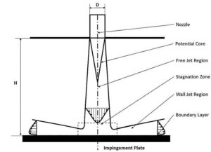
An impinging jet is a fluid jet that strikes a surface vertically or at a specific angle for cooling or heating. In this case, the post-impact flow develops on the surface, creating a thermal boundary layer. As it moves in a peripheral direction, the thickness of this boundary layer increases, and consequently, the rate of heat transfer decreases. Therefore, due to the minimum thickness of the thermal boundary layer and the maximum amount of flow turbulence in the collision area, the amount of heat transfer in this area increases significantly compared to other areas. Following figure shows the impinging jet with the wall and an overview of the flow after the collision.
Impinging jets have excellent heat transfer properties due to their turbulence and high speed. For this reason, impinging jets are used today in many industrial applications such as food, wood, paper, fiber, glass, as well as in ventilation, combustion, cooling of steel plates and gas turbines. Impinging jets can be divided into three general areas: free jet region, stagnation zone, and wall jet region. Among the geometric parameters that characterize the impinging jet is the diameter or width of the nozzle outlet and the distance of the nozzle to the impact plane. Speed, velocity profile, temperature, and turbulence intensity at the nozzle outlet are the determinants of flow in impinging jets.
Project Description
After the current exits the nozzle, the jet expands in the free jet area by sucking the surrounding current and increasing its mass flow rate. It then strikes the plate in the stagnation zone and changes direction.
Although many Navier-Stokes equations using the Reynolds averaging (RANS) method have been used in many numerical studies on impinging jets due to the complexity and turbulence of the flow due to their low computational cost and time, many researchers have used the SST kw method to simulate an impinging jet numerically. In this project, the SST k-w method has been used for modeling turbulence by ANSYS Fluent software.
Impinging Jet Geometry & Mesh
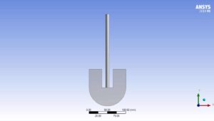
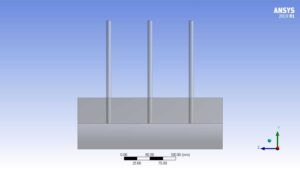
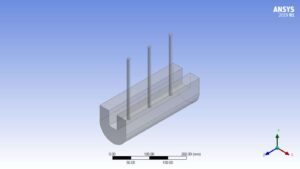
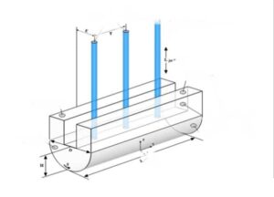
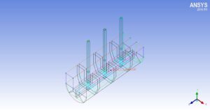
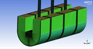
To draw this geometry, Design Modeler software from ANSYS software subsets has been used, the geometry of which can be seen in the following figures.
| Size | symbol
|
Title |
| 10 d | d | Jet diameter |
| 20 d | L-jet | Jet length |
| 100 | D | Concave-plate diameter |
| 5 d | H | Collision distance |
| 8 d | P | Distance from center to center of jets |
| 288 d | L | Concave page length |
| 2 d | E | Distance from the center of the jet to the outlet edge |
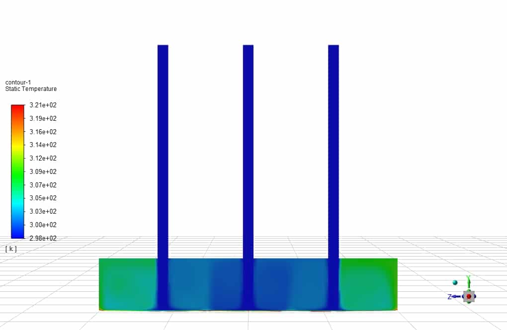
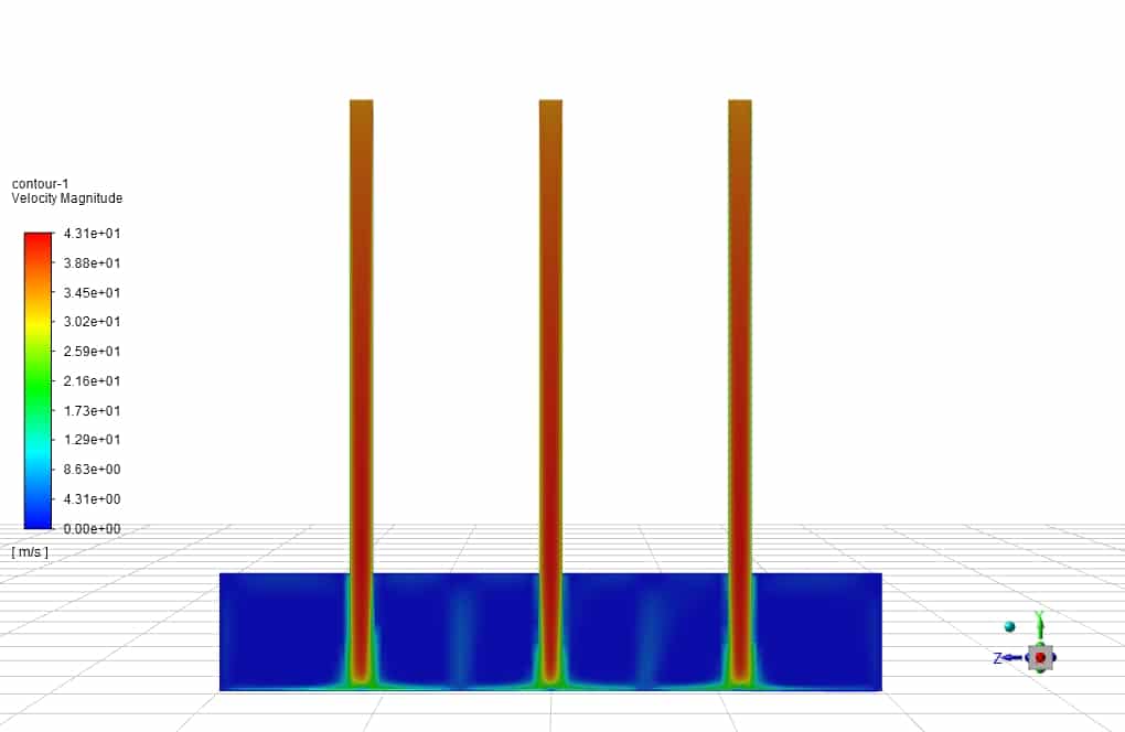
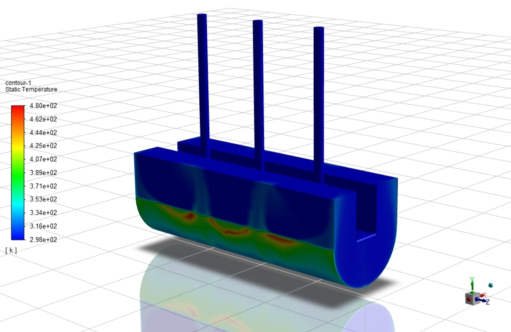
In this case, the fluid flow hits the U-shaped wall in the form of a jet. For example, the fluid flows at high velocities in three different Reynolds, about 35 m/s. As the temperature rises, it exits the outlets. This study aims to investigate the convection heat transfer in the collision of the fluid with the u-shaped walls and the effect of Reynolds on the amount and rate of heat transfer formed.
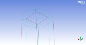
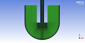
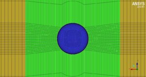
ICEM CFD software has been used to mesh the desired geometry.
Gridding is done using Hexa elements and in a structured way using blocking.
Given the number of elements reported in this article, we refrain from re-examining the mesh independence and use the number of its final elements.
The number of elements used in this simulation is 2700,000 hexahedral elements, the images of which are shown below:
Impinging Jet CFD Simulation
We consider several assumptions to simulate the present model:
- We perform a pressure-based solver.
- The simulation is steady.
- The gravity effect on the fluid is equal to -9.81 m.s-2 along the vertical axis.
The following table represents a summary of the defining steps of the problem and its solution:
| Models | ||
| Viscous | k-omega | |
| k-omega model | SST | |
| Boundary conditions | ||
| Inlet | Velocity Inlet | |
| velocity magnitude | 34.89 m.s-1 | |
| Temperature | 298 k | |
| Outlet | Pressure Outlet | |
| gauge pressure | 0 atm | |
| Jet wall | wall | |
| U shape plate | Wall | |
| Temperature | 298 k | |
| flux | 5000 w.m-2 | |
| walls | wall | |
| Methods | ||
| Pressure-Velocity Coupling | Coupled | |
| Pressure | PRESTO | |
| gradient | Less squares cell-based | |
| momentum | first order upwind | |
| turbulent kinetic energy | first order upwind | |
| specific dissipation rate | first order upwind | |
| Initialization | ||
| Initialization methods | Standard | |
| gauge pressure | 0 Pascal | |
| velocity | 10 m.s-1 | |
| Material | ||
| Material properties | Standard | |
| density | 1.225 kg.m-3 | |
| viscosity | 1.086e-6 kg.m-1.s-1 | |
Results
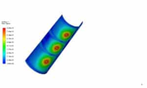
The following figure shows Y plus on a concave surface:
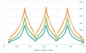
The Nusselt number is obtained according to the amount of temperature obtained on the line at the bottom of the U-shaped plate in its center in the X direction and the temperature in that relation. By changing the input velocity of the impinging jet, we can change the Reynolds number, and with three different Reynolds 23000, 14000, and 40,000, we examined the Nusselt number.
Nu=hk/L=hLk
The following figure shows a graph of the Nusselt number in this simulation in terms of various Reynolds Numbers.
Impinging Jet Analysis
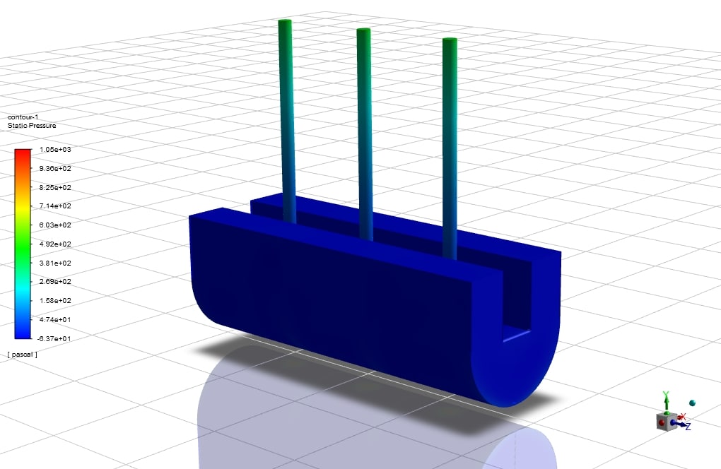
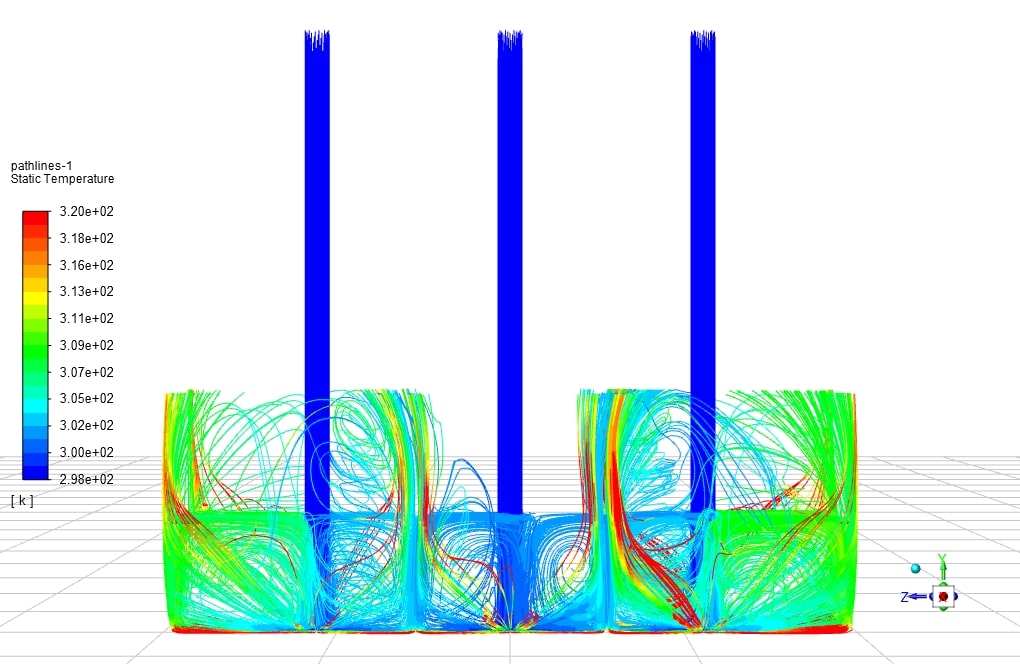
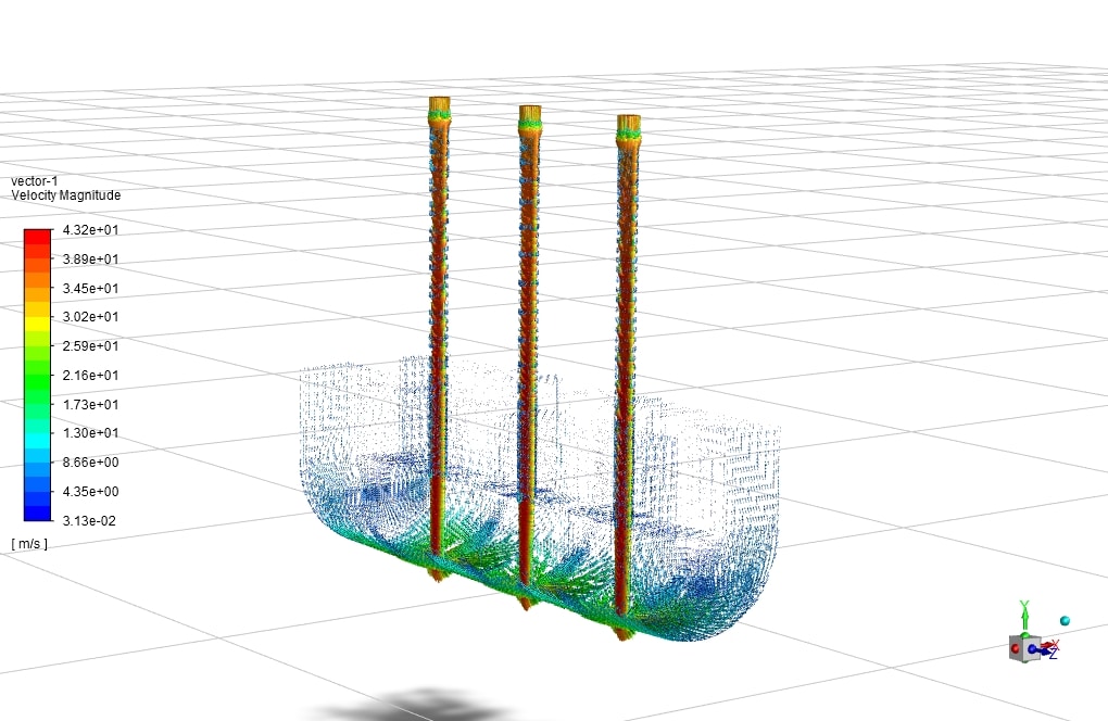
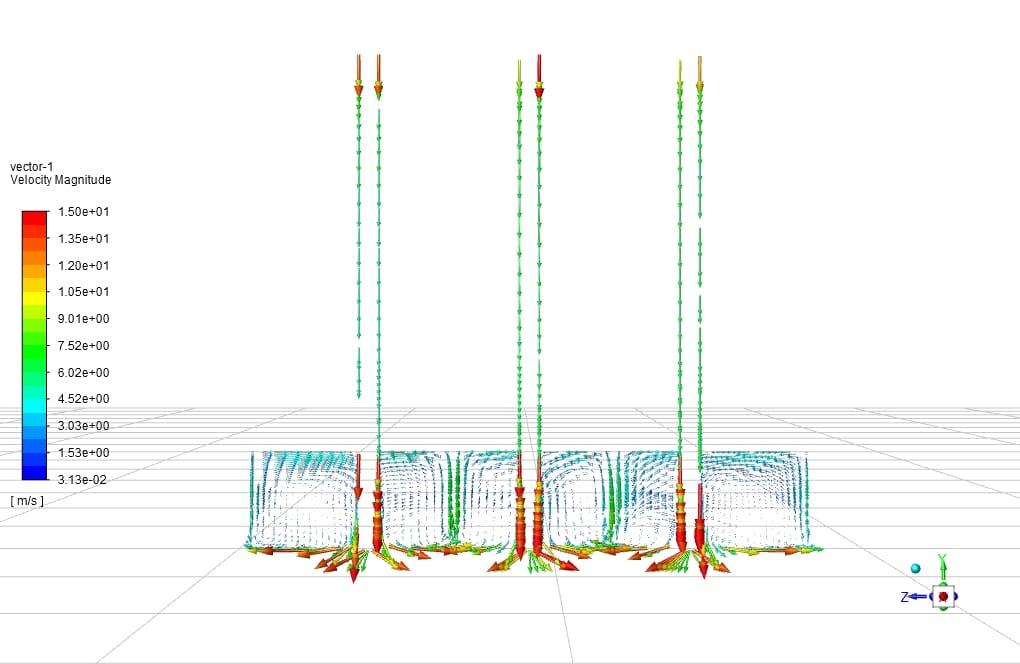
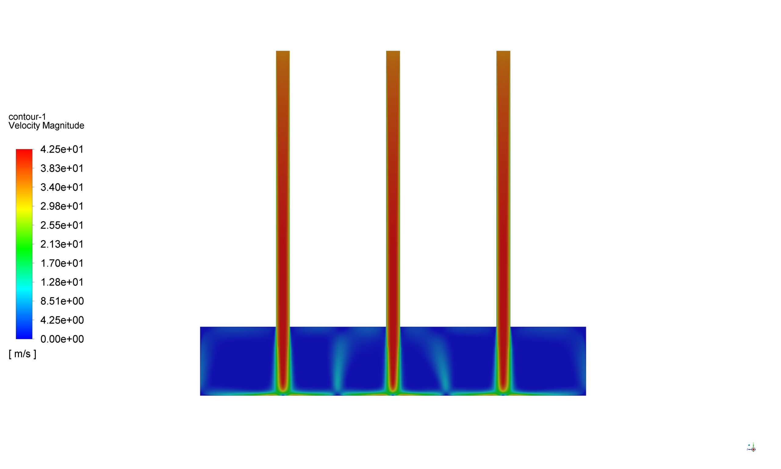
The amount of pressure at the point where the jet hits the plate has the maximum value. The negative pressure gradient causes the velocity to reach its maximum value as it progresses from the point of impact in the radial direction to the outside of the plate. Positive pressure is applied at the boundary of the stagnation zone and the gradient wall. As a result, the velocity decreases, and the pressure increases as it advances in the jet area of the wall. The maximum value of the Nusselt number is obtained at the stagnation point because the thickness of the boundary layer is the lowest at this point. As the current moves toward the wall jet, the thickness of the boundary layer increases. As a result, the Nusselt number decreases. At distances from the nozzle to the plane H / d <5, the Nusselt number on the collision surface has two maximums.
The first maximum at the point of stagnation is due to the structure of large-scale vortices that increase the fluid velocity and thus increase the Nusselt number. The second maximum can be considered due to the transition from slow to turbulent in the transition zone.
Impinging Jet Analysis
On the other hand, in the second maximum location, induction vortices are created due to the interaction of large-scale vortices and impact surfaces, which increase heat transfer. Mach number is a measure of fluid compressibility. Fluids below 0.3 are incompressible at Mach numbers, and fluids are compressible at Mach numbers above. In incompressible fluids at the nozzle to low plate distances, the second maximum in the Nusselt number is more significant than its value for compressible fluids. This phenomenon is because induction vortices at the second maximum location are larger in incompressible fluids than in compressible fluids. The aspect ratio (AR) of the nozzle section can affect the heat transfer. The larger the aspect ratio, the higher the heat transfer. The highest heat transfer occurs at the stationary point at H / d = 6.
Impinging Jet Analysis
On the other hand, in H / d> 5, the secondary peak is not seen in the Nusselt number. Heat transfer increases by increasing turbulence at the jet outlet. This is due to the strengthening of the vortex structure. As the number of jets increases, the Nusselt number of the stationary point does not change, but the total heat transfer can be increased. In this case, if we choose an optimal value for H / d and S / d, we can reach the maximum heat transfer. By increasing the angle of impact at shorter distances from the nozzle to the location plane, the maximum Nusselt number is shifted, and its value is also increased. As the frequency at the nozzle output increases, the Nusselt number first increases and then decreases. Due to parameter changes on the Nusselt number, the maximum Nusselt number can be reached by optimally combining them.





Reviews
There are no reviews yet.