Jet Impact on Resident Water CFD Simulation, Ansys Fluent Training
$80.00 $40.00 Student Discount
In this project, jet impact on resident water has been simulated and the results of this simulation have been investigated.
Click on Add To Cart and obtain the Geometry file, Mesh file, and a Comprehensive ANSYS Fluent Training Video.To Order Your Project or benefit from a CFD consultation, contact our experts via email (info@mr-cfd.com), online support tab, or WhatsApp at +44 7443 197273.
There are some Free Products to check our service quality.
If you want the training video in another language instead of English, ask it via info@mr-cfd.com after you buy the product.
Description
Jet Impact Project Description
The system consists of two different fluids, including water as the primary fluid and one secondary fluid is Air. The Eulerian multiphase model has been used. The jet-air is entering the domain with the speed of 24 m/s with gravity considered as -9.81 m/s-2 on the y-axis.
Geometry & Mesh
The 3-D geometry of the present model is carried out using Design Modeler software. The geometry consists two-section, the lower section is resident water, and the upper section contains outlet and velocity inlet; tank sides are considering as well.
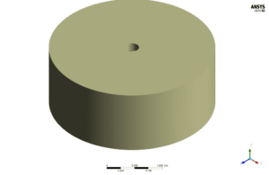
The meshing of this present model has been generated by ANSYS Meshing software. The mesh grid is unstructured with no element quality lower than 0.52, and the total cell number is 795842. the figure below shows an overview of the performed mesh.
Jet Impact CFD Simulation
To simulate the present model, several assumptions are considered, which are:
- The solver is pressure-based and transient.
- Simulation has only examined fluid behavior; in other words, heat transfer simulation has not been performed.
- The effect of gravity on the flow is considered to be 9.81 m.s-2 and along with the y-axis in the present model.
The following is a summary of the steps for defining the problem and its solution:
| Models | ||
| K-omega | Viscous model | |
| standard | k-omega model | |
| shear flow corrections | k-omega options | |
| water | primary phase | |
| air | secondary phase | |
| explicit | formulation | |
| Boundary conditions | ||
| Velocity-inlet | inlet | |
| 0 | initial gauge pressure | mixture |
| 24 m/s | velocity magnitude | air |
| 1 | volume fraction | |
| Pressure outlet | outlet | |
| 1 | backflow volume fraction | air |
| 0 | backflow volume fraction | water |
| wall | wall | |
| stationary wall | wall motion | |
| Solution Methods | ||
| Phase coupled | pressure-velocity coupling | |
| PRESTO! | pressure | |
| first-order upwind | momentum | |
| first-order upwind | specific dissipation rate | |
| first-order upwind | volume fraction | |
| Initialization | ||
| standard | initialization method | |
| 34 m/s | water velocity (0,y,0) | |
| 0 m/s | air velocity (x,y,z) | |
| 1 | the secondary phase volume fraction | |
Results
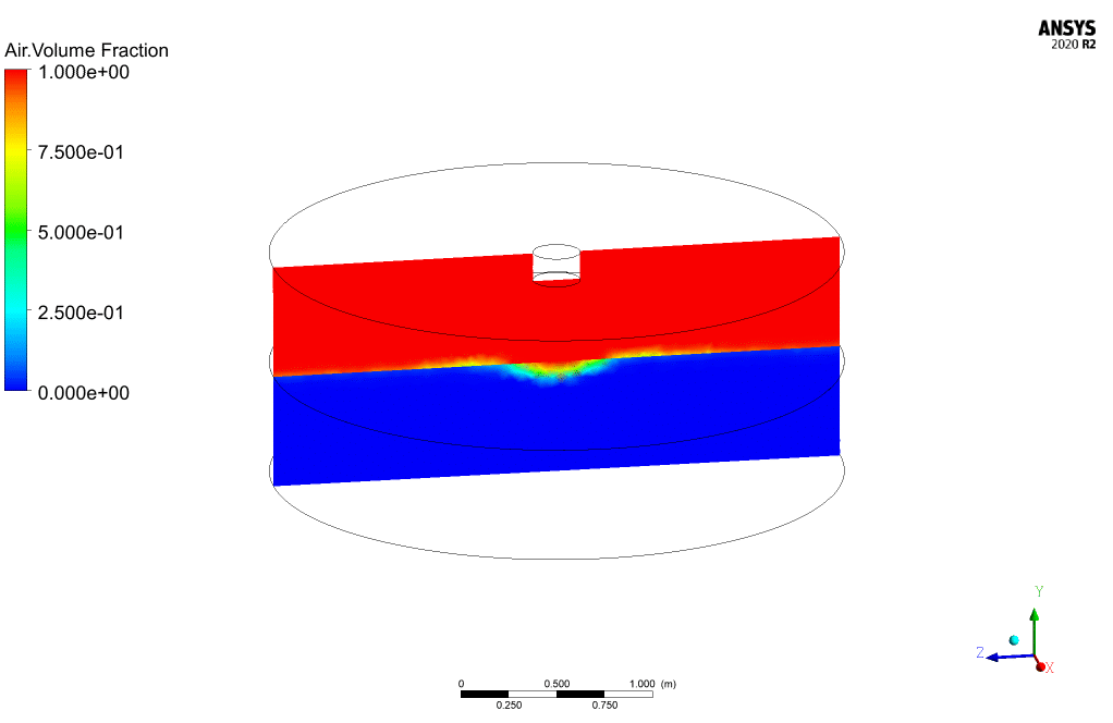
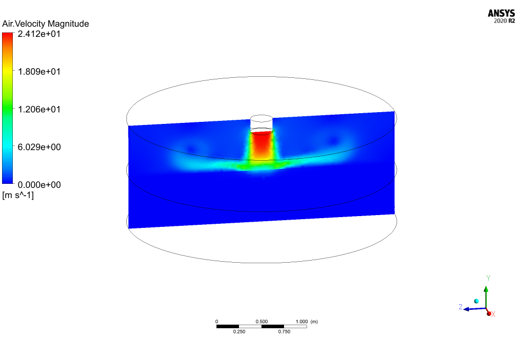
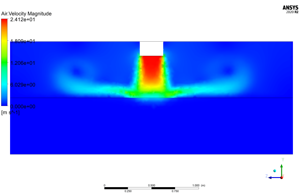
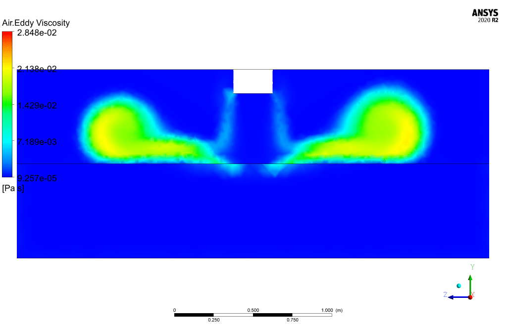
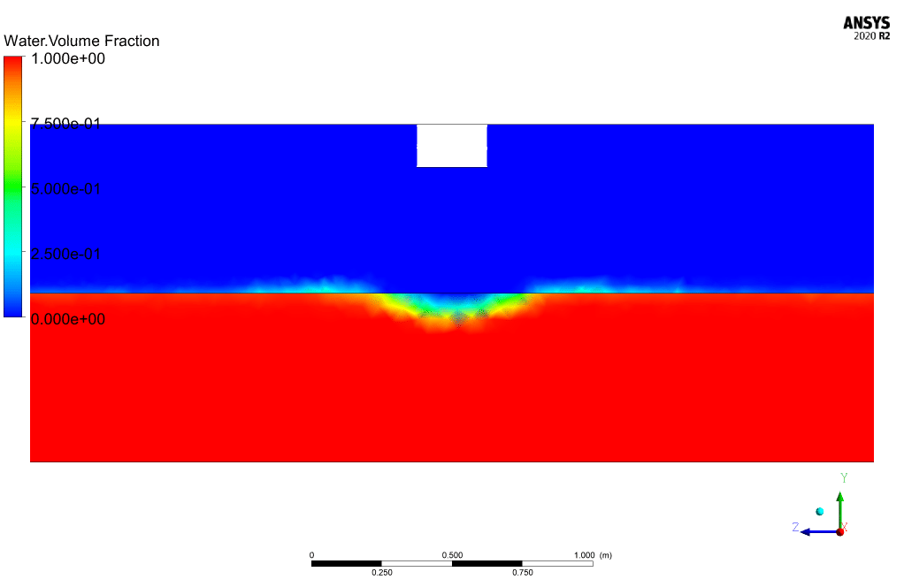
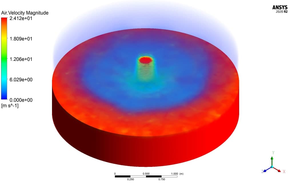
At the end of the solution process, two-dimensional and three-dimensional velocity, air and water volume fraction, and animation of filling fountain are obtained. The jet-air enters domain from nozzle shape inlet by time develops jet flow and impacts resident water. The result shows water sliding insides and making vortex on the surface—jet flow after losing kinetic energy vent out from pressure outlet.
[/vc_column_text]


Beatrice –
Hi. What time step sized has been used for this simulation?