Liquid Fuel Combustion Inside a Chamber Using DPM
$180.00 $90.00 Student Discount
- In this project, liquid fuel combustion is simulated using DPM module.
- The geometry was designed in SpaceClaim, and a mesh with 769000 elements was generated using ANSYS Meshing.
- The species transport module is employed.
- The fuel is ethanol and the oxidizer is nitrous oxide.
To Order Your Project or benefit from a CFD consultation, contact our experts via email (info@mr-cfd.com), online support tab, or WhatsApp at +44 7443 197273.
There are some Free Products to check our service quality.
If you want the training video in another language instead of English, ask it via info@mr-cfd.com after you buy the product.
Description
Project Description
liquid fuel Combustion processes have been at the core of energy production and propulsion systems for over a century, providing the necessary thrust and power for a wide range of applications. Among the various types of fuels, liquid ethanol (C2H5OH) has gained attention as a renewable and cleaner-burning alternative to fossil fuels. When paired with an oxidizer such as nitrous oxide (N2O), ethanol can undergo a vigorous combustion reaction, releasing energy that can be harnessed for various industrial and technological purposes.
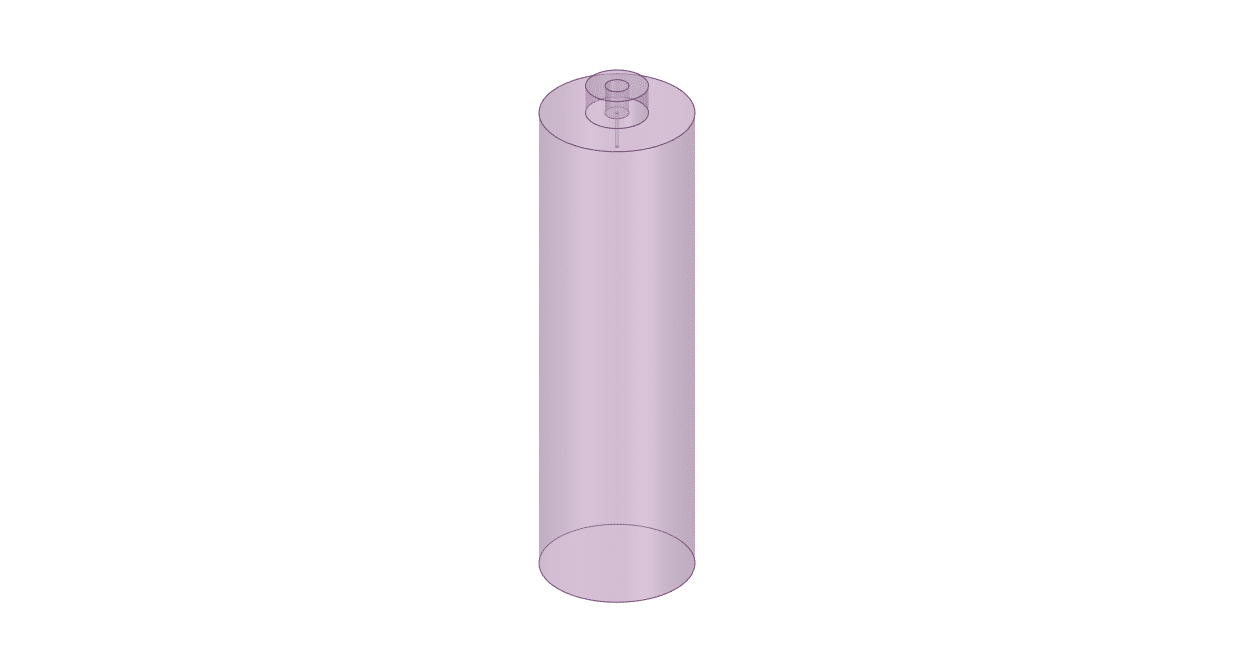
The geometry is designed using Spaceclaim software. The combustion chamber has 6000mm diameter with a fuel nozzle in the center. The model is then divided into elements in ANSYS Meshing software. In total, 769000 elements are generated.
Methodology
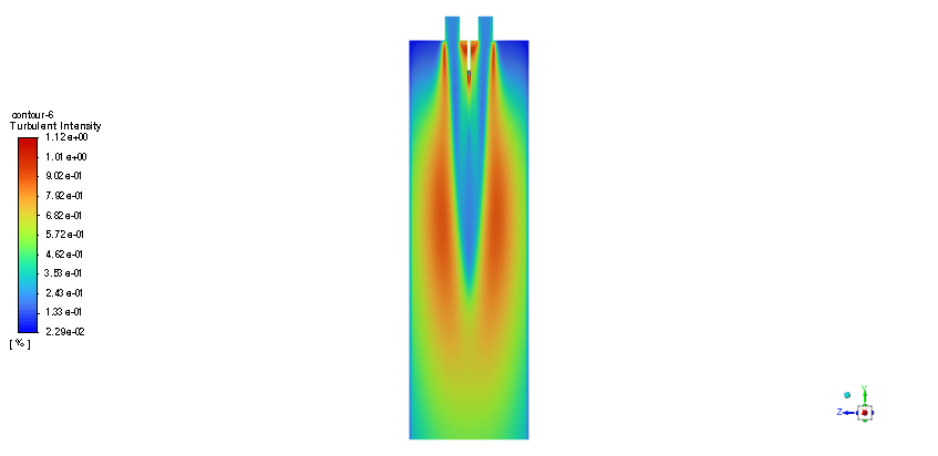
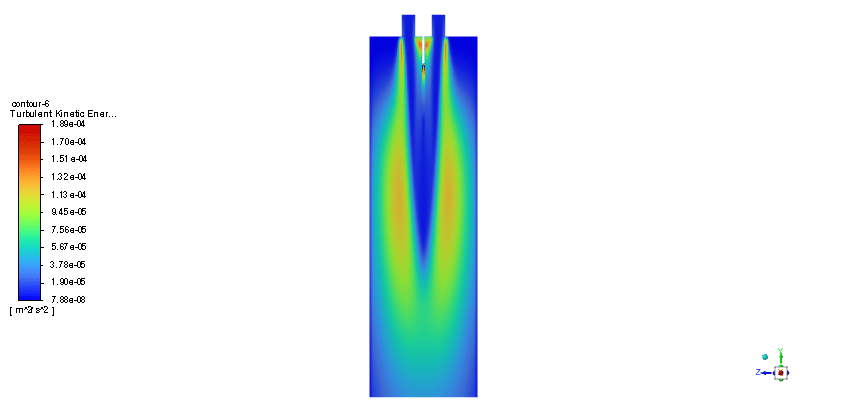
In order to model the fuel liquid droplets, two-way DPM module is used. Although the continuous phase is solved in steady mode, the discrete phase is tracked unsteadily. Moreover, the Standard K–epsilon turbulence model is utilized to predict flow behavior. Also, the Species Transport regarding the volumetric reaction and Eddy dissipation turbulent-chemistry interaction model is employed to simulate the combustion of ethanol and nitrous oxide.
Results
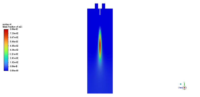
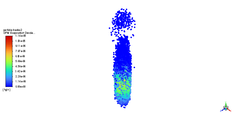
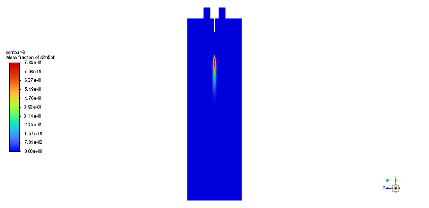
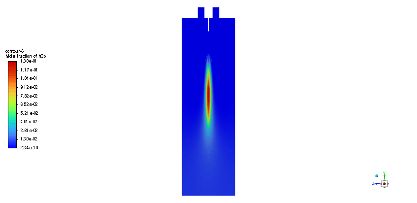
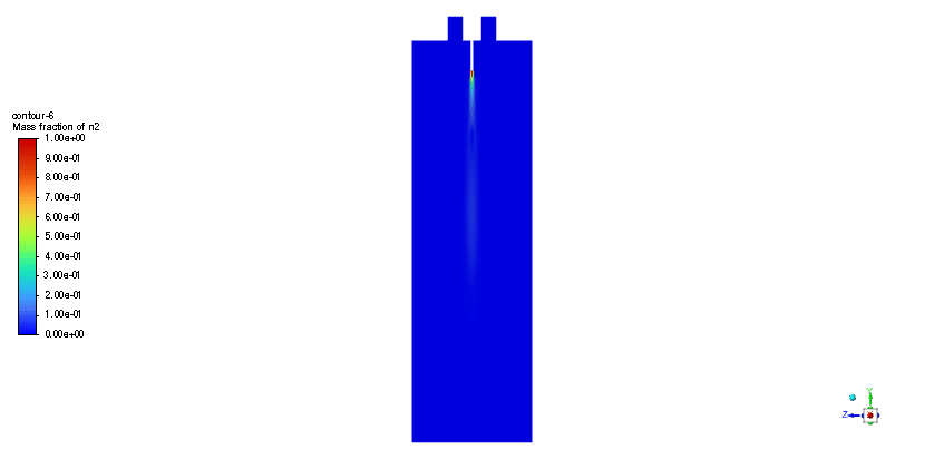
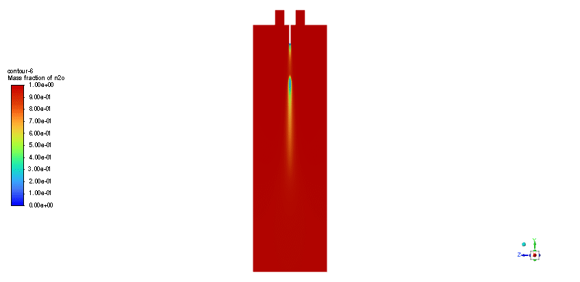
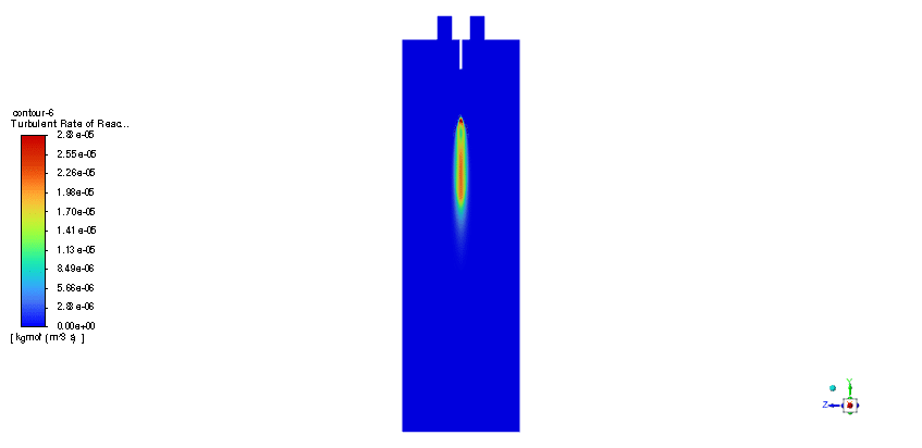
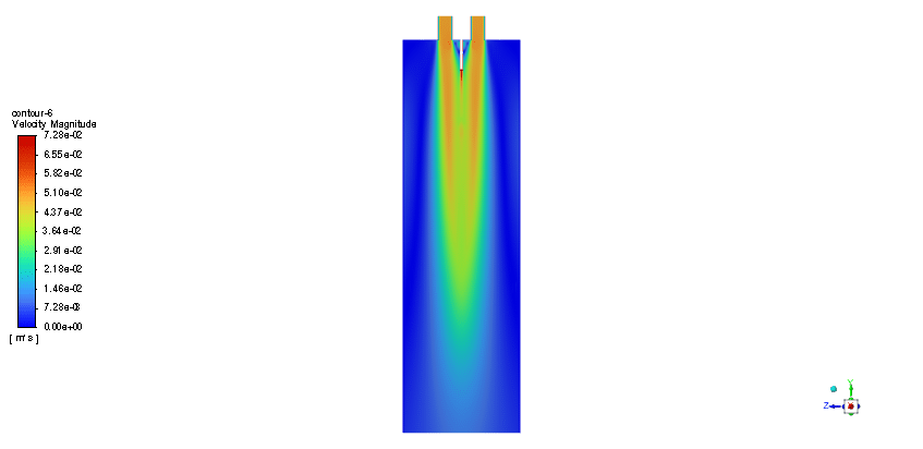
The simulation is performed in two major steps. Firstly, the continuous phase were solved. The velocity and pressure distribution reaches its steady condition after a while. Thus, the chamber average temperature reaches 320K and it is filled with nitrous oxide. It is time to start injection of fuel which is ethanol. The injection temperature is 273.15K and it injects 0.5mm fuel droplets into the chamber. The fuel temperature increases over time until it reaches its devolitization temperature. Thus, ethanol gas releases and get the chance to mix with oxidizer (N2o) and react. As a result, the temperature increases dramatically up to 460K (in average) and some products are produced based on the below reaction:
3C2h5oh + 2N2o ===> 3Co2 + 4H2o + 2N2


Lora Koss –
I was impressed by the use of ethanol as a renewable fuel source for combustion. Has the combustion efficiency of ethanol been compared to traditional fossil fuels in this study?
MR CFD Support –
Thank you for your positive feedback about the usage of ethanol in our study. Our simulation primarily focused on the combustion process of ethanol with nitrous oxide and assessed its performance within the constraints of the designed combustion chamber. Traditional comparisons of ethanol’s efficiency with fossil fuels were not within the scope of this particular simulation, but we acknowledge that such analyses are crucial for a comprehensive understanding of alternative fuel advantages.
Harvey Goldner –
From what I’ve read, this training showed an increase in temperature due to the combustion process. Can you tell me what combustion byproducts were observed after the completion of the reaction and how this may impact the efficiency of the process?
MR CFD Support –
In this simulation, the main byproducts of the combustion of ethanol with nitrous oxide as per the provided balanced chemical equation are carbon dioxide (CO2), water vapor (H2O), and nitrogen (N2). These byproducts indicate a complete combustion process; thus, efficiency is likely to be high due to the generation of minimal unburned fuel. High temperatures up to 460K average are indicative of the energy being released by the combustion process, which is useful for propulsion and energy applications.
Katelyn Bartell –
I’m delighted with how comprehensive the simulation is, showing the combustion of ethanol. Was the distribution of temperature and products like CO2 and H2O visibly clear in the results as well?
MR CFD Support –
Thank you very much for the positive feedback! We are glad to hear that you appreciated the detailed modeling process. Yes, the simulation results include clear distributions of temperature and the products of combustion. These are represented in detailed visuals, including contour and vector plots, allowing for an in-depth analysis of how the temperature, CO2, and H2O are distributed throughout the combustion chamber after the reaction occurs.
Dr. Kenton Welch –
The results section mentions dramatic temperature increases. What materials are chosen for the chamber walls to withstand such high temperatures?
MR CFD Support –
The project description does not specify the materials used for the chamber walls. However, typically materials with high thermal resistance and stability such as specific steel alloys or ceramic materials could be used to withstand the high temperatures during the combustion of liquid ethanol and nitrous oxide as described.
Dr. Yoshiko Frami II –
What specific characteristics of ethanol and nitrous oxide’s combustion reaction are considered in the Species Transport model, such as reaction rate or energy release?
MR CFD Support –
In the Species Transport model, the reaction between ethanol and nitrous oxide is characterized by parameters like the chemical reaction rate, stoichiometric coefficients, and heat of reaction. These details influence how quickly the reactants are consumed, the rate at which products are formed, and the amount of energy released during combustion, which affects temperature profiles and flame characteristics within the chamber.
Hattie Hermiston –
I’m impressed with the combustion analysis of liquid ethanol and nitrous oxide using the DPM method. The temperature rise within the chamber after fuel injection is particularly interesting. I appreciate this thorough and insightful simulation!
MR CFD Support –
Thank you for your positive feedback on our liquid fuel combustion simulation project! We are delighted to hear that you found the analysis and results, especially the temperature changes during combustion, insightful. It’s great to know our product exceeded your expectations. If you have further questions or need assistance with similar projects, please feel free to reach out to us.