Lobe Pump CFD Simulation, ANSYS Fluent Training
$240.00 $120.00 Student Discount
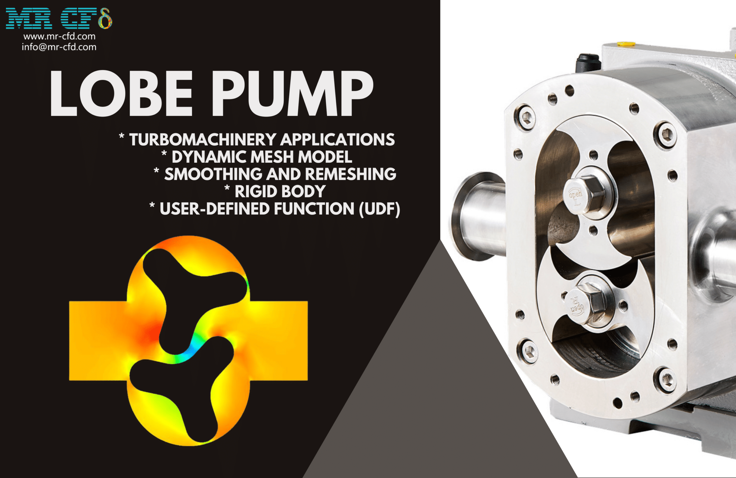
- The problem numerically simulates the Lobe Pump using ANSYS Fluent software.
- We design the 2-D model with the Design Modeler software.
- We mesh the model with ANSYS Meshing software, and the element number equals 128,072.
- We perform this simulation as unsteady (Transient).
- We use the Dynamic Mesh Model to define deforming and moving zones.
- We use the user-defined function (UDF) to define the rotational motion of lobes.
To Order Your Project or benefit from a CFD consultation, contact our experts via email (info@mr-cfd.com), online support tab, or WhatsApp at +44 7443 197273.
There are some Free Products to check our service quality.
If you want the training video in another language instead of English, ask it via info@mr-cfd.com after you buy the product.
Description
Description
This project is related to the numerical simulation of the Lobe Pump using ANSYS Fluent software. A pump is a mechanical device for moving and transferring all liquids from one place to another. In this way, by increasing the pressure, pumps cause liquids to move to a higher height (by increasing the head) and even lower (such as tanks).
The pump takes mechanical energy from an external source, such as an engine, and transfers it to the fluid passing through it. As a result, the energy of the fluid increases after leaving the pump.
The energy transfer to the pump fluid is done in two dynamic and displacement methods. Therefore, pumps are divided into positive displacement pumps and dynamic or non-positive displacement pumps. Positive displacement pumps are divided into two groups: rotary (such as gear, lobe, and vane) and reciprocating (piston and diaphragm).
A lobe pump is one of the most common pumps to increase the hydraulic power of a fluid. Lobe pumps move liquids using lobes. These pumps are similar to gear pumps, except the lobes are designed almost to meet rather than touch and turn each other.
Lobe pumps consist of two lobes that rotate in opposite directions. When two lobes make contact with each other, fluid is trapped. Now, when the lobes are separated from each other due to rotation, high-pressure fluid is rotated through the lobes to the outlet.
In this project, we simulated the water flow inside a lobe pump. We aim to model the rotation of two lobes inside the pump. The rotation of the lobes momentarily changes the fluid’s behavior in the pump. So, the mesh of the computing domain deforms over time.
We modeled the geometry of the project using Design Modeler software. The geometry is related to a lobe pump. The computational domain includes the internal space of the pump with two superimposed lobes. Then we meshed the model with ANSYS Meshing software. The model mesh is unstructured, and the number of cells equals 128,072.
Lobe Pump Methodology
The Dynamic Mesh Model is used for the simulation. We generally use a dynamic mesh whenever we have a moving boundary or a deforming zone.
Here, two lobes are rotating in opposite directions. So this causes the mesh to deform over time. Therefore, we define a Rigid Body to define the rotational motion of the lobes. We use a user-defined function (UDF) to define the motion of the rigid body.
According to the rotational motion of the lobes as a rigid body, the mesh zone around the gears is deformed. So, for this zone, we use the Deforming option.
Due to the nature of this modeling, fluid behavior is time-dependent. Hence, we use the unsteady (Transient) solver.
Conclusion
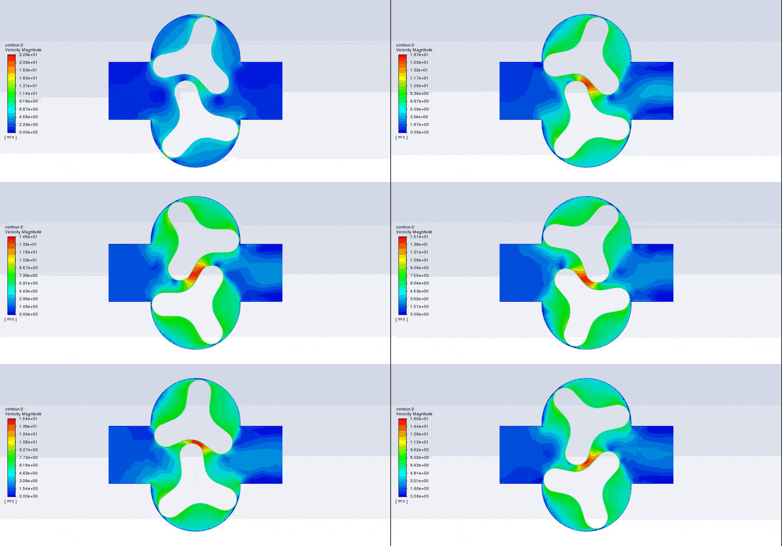
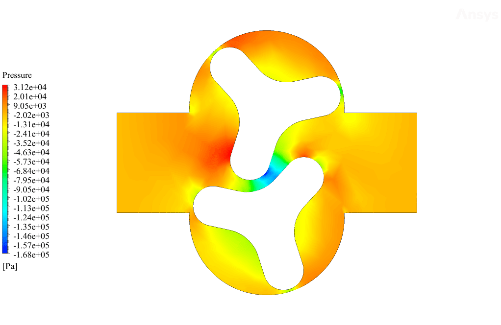
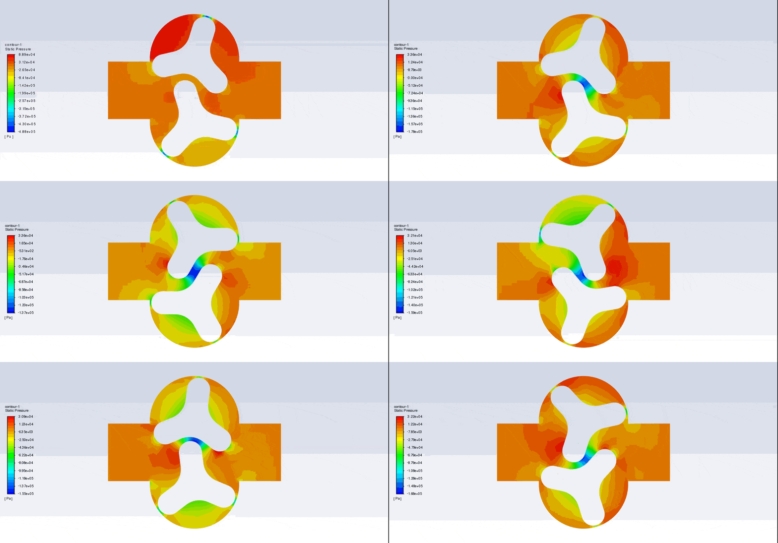
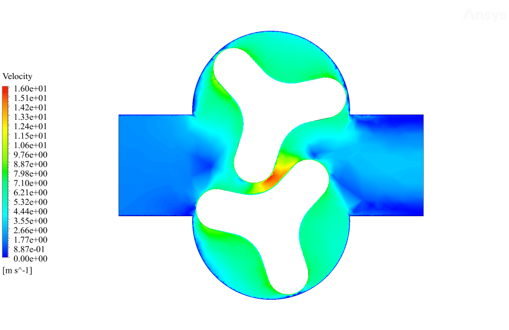
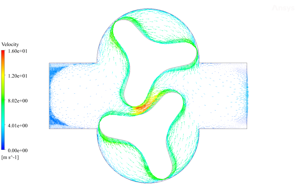
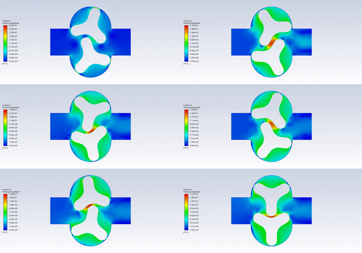
After the solution, we obtained pressure, velocity contours, and velocity vectors. Because the lobes rotate over time, we obtained the velocity and pressure contours and the velocity vector animation.
The results show that this lobe pump is working correctly. This pump can transfer the fluid well and increase the fluid’s pressure. The fluid is trapped in the space between the gears in contact. Then this fluid is pushed towards the outlet with high pressure.




Reviews
There are no reviews yet.