Lubrication, Piston-Ring Pack Friction (Moving Wall), ANSYS Fluent CFD Simulation Training
$100.00 $50.00 Student Discount
The present problem simulates the lubrication process effect on friction factor in the space between the cylinder and the ring in an engine considering various groove texture patterns.
Click on Add To Cart and obtain the Geometry file, Mesh file, and a Comprehensive ANSYS Fluent Training Video.To Order Your Project or benefit from a CFD consultation, contact our experts via email (info@mr-cfd.com), online support tab, or WhatsApp at +44 7443 197273.
There are some Free Products to check our service quality.
If you want the training video in another language instead of English, ask it via info@mr-cfd.com after you buy the product.
Description
Lubrication Project Description
The present problem simulates the lubrication process effect on friction factor in the space between the cylinder and the ring in an engine considering various groove texture patterns by ANSYS Fluent. The movement of the ring on the inner surface of the cylinder of an engine causes friction between the surfaces. The lubrication process can be used to reduce friction between surfaces; In this way, oil is poured into the space between these two surfaces. The oil in this model has a density of 900 kg.m-3, specific heat capacity equal to 210 j.kg-1.K-1, thermal conductivity equal to 0.13 Wm-1.K-1, and viscosity equal to 0.04 kg .m-1.s-1.
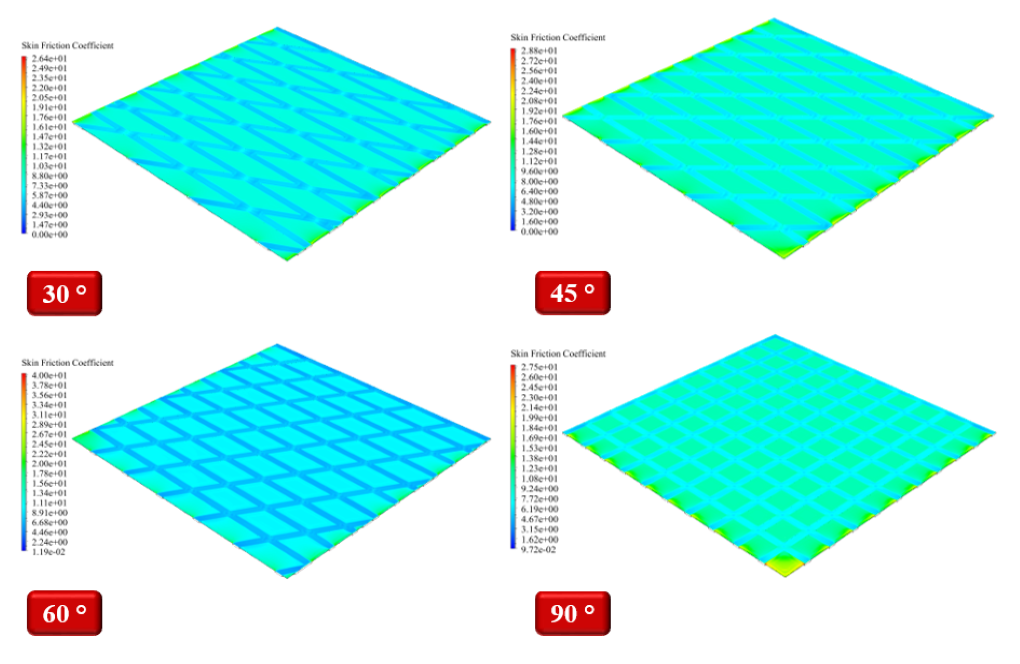
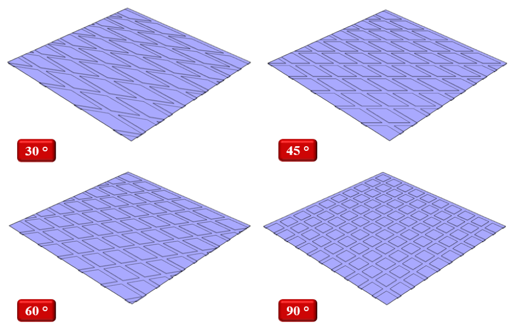
On the inner surface of the cylinder, there are grooves where the oil flows in the space between these grooves. These surfaces can be designed with different patterns based on the angle and density of the grooves placed on them. In the present modeling, four patterns have been used for these grooves, including 30, 45, 60, and 90-degree angles. The present project aims to investigate the amount of friction coefficient produced on the moving surface of the ring. In the present simulation, a square computational area is defined in which several rows of grooves with the mentioned angles are designed.
Lubrication Project Description
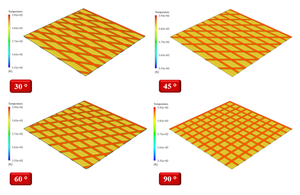
The lower surfaces of this area and its grooves are defined as a static wall, and the smooth upper surface of the area is defined as a moving wall. Since this square area is defined as a sample space of a general computational area, the lateral surfaces of the grooves have a symmetric boundary condition. The lower stationary wall has a constant temperature of 353 K, and the upper moving wall has a constant temperature of 393 K. Because the modeling is done in four different patterns based on the angle of the grooves, the oil flow path inside these grooves will be different.
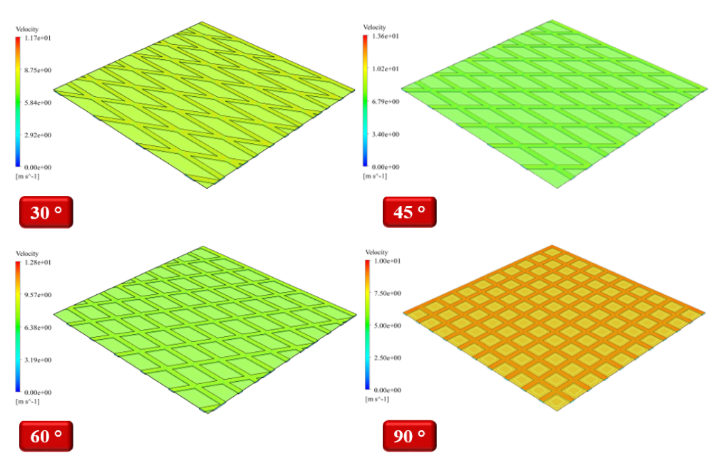
Now, considering that when a high-moving surface moves on these grooves, the path of movement of this surface with the grooves creates an angle equal to half the angle between the two grooves; Therefore, the bisector of the mentioned angles is used to define the amount of velocity of the moving wall relative to its side grooves. This moving wall in all four modes has a velocity equal to 10 m.s-1. Using the sine and cosine of angles of 15, 22.5, 30, and 45 degrees can have different velocities in two different ways coordinate directions.
Geometry & Mesh
The current model is designed in three dimensions using Design Modeler software. The model includes a square computational area with 0.001 m for fluid flow. This computational area has 20 rows of grooves with a depth of 0.000006 m. These rows of grooves are designed in two different directions and make different angles to each other. These grooves are designed based on the angle of relation to each other, with four different patterns, which include modes with angles of 15, 30, 45, and 90 degrees.
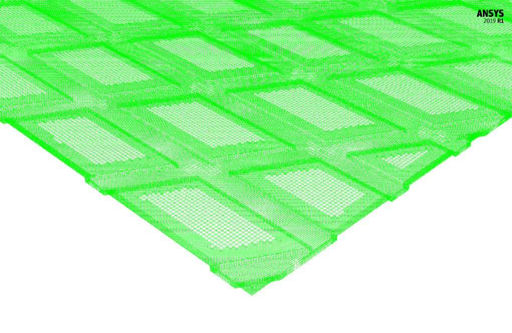
The meshing of the present model has been done using ANSYS Meshing software. The mesh type is structured and the element number in grooved modes with angles of 30, 45, 60 and 90 degrees is equal to 633774, 645574, 642332, and 692403, respectively. The following figure shows a view of the mesh for the 60 ° groove mode.
Lubrication CFD Simulation
To simulate the present model, several assumptions are considered:
- We perform a pressure-based solver.
- The simulation is steady.
- The gravity effect on the fluid is ignored.
A summary of the defining steps of the problem and its solution is given in the following table:
| Models | ||
| Viscous | k-epsilon | |
| k-epsilon model | standard | |
| near wall treatment | standard wall functions | |
| Energy | On | |
| Boundary conditions | ||
| Upper Wall | Wall | |
| wall motion | moving wall | |
| temperature | 393 K | |
| Downer Wall | Wall | |
| wall motion | stationary wall | |
| temperature | 353 K | |
| Methods | ||
| Pressure-Velocity Coupling | Coupled | |
| Pressure | second order | |
| momentum | second-order upwind | |
| energy | second-order upwind | |
| turbulent kinetic energy | first-order upwind | |
| turbulent dissipation rate | first-order upwind | |
| Initialization | ||
| Initialization methods | Hybrid | |
Results
At the end of the solution process, three-dimensional contours related to pressure, velocity, and temperature and a two-dimensional friction coefficient contour and plots are obtained.
Y+ (Y plus)
Friction Factor




Grady Zemlak –
The simulation provides data on different groove angles impact on friction, but how is the roughness of the groove surfaces accounted for in the simulation? Does the study consider varying surface roughness or is it assumed to be uniform across all models?
MR CFD Support –
In this simulation, we specifically focus on the impact of varying groove angles on friction in the lubrication process. The study considers different groove angles (30, 45, 60, and 90-degree angles) to understand how they can affect the lubrication performance. However, the surface roughness of the grooves is not a variable in the present simulation; it is assumed to be uniform across all models to isolate the effect of groove angle on the coefficient of friction.
Gertrude Schneider –
I was amazed at how the different groove angles impacted the lubrication and friction factor. The level of detail in the simulation shows clearly in the results!
MR CFD Support –
Thank you for your positive feedback on the Lubrication, Piston-Ring Pack Friction CFD Simulation Training using ANSYS Fluent. We are glad that you found the effect of groove texture patterns on lubrication and friction factors insightful. Accomplishing this level of detail in simulations empowers better engineering designs, and we’re happy to hear that our product contributed valuable insights. If you have further questions or need more information, please feel free to reach out!
Joaquin Crona –
Can you explain how the surface patterns of grooves affect the lubrication efficiency in this simulation?
MR CFD Support –
The surface patterns of grooves affect the flow path of the oil and create different pressure distributions and flow dynamics. This, in turn, impacts the lubrication efficiency. Various groove patterns are analyzed to determine their influence on the friction coefficient between the piston ring and the cylinder’s surface.
Miss Ashtyn Wisoky DVM –
The tutorial was incredibly detailed and informative. I particularly appreciated the visual aids provided in the mesh views, which made it much easier to understand the complex groove texture patterns. Also, seeing the results in various contour plots at the end provided clarity on the relationship between groove geometry and friction coefficient. Fantastic practical resource for anyone studying fluid dynamics in mechanical engineering applications!
MR CFD Support –
Thank you for your positive feedback! We’re thrilled to hear that our tutorial was able to help you visualize and understand the key concepts of CFD simulations with groove texture patterns. If you have any more questions or need further simulations, feel free to reach out. We’re always here to help you enhance your understanding of fluid dynamics!
Ms. Cassandra Grant DDS –
The groove texture patterns in the simulation are quite intriguing. How exactly do the different groove angles affect the lubrication performance and the resulting friction coefficient between the cylinder and the ring?
MR CFD Support –
Different groove angles affect the flow path of the oil and its ability to provide lubrication. Generally, optimal groove patterns can improve oil distribution, reducing direct metal-to-metal contact, and thus lowering friction coefficients. Each groove angle creates a different interaction with the moving surface, affecting how the lubricant responds to changes in pressure and motion.
Dr. Rhett Runolfsson –
Can the groove patterns be customized according to my specifications for a particular engine design?
MR CFD Support –
In this simulation, four different groove patterns based on certain angle criteria have been designed. However, customizations aligned with specific engine designs can typically be conducted through consultation with the technical team to adapt the computational model accordingly.
Cecile Friesen –
The description mentioned using various groove texture patterns. How does changing these groove angles affect the lubrication efficiency and the friction factor?
MR CFD Support –
Changing the groove angles in the texture pattern can have significant effects on lubrication efficiency and the friction factor. Grooves alter the flow path of the lubricant, potentially improving the distribution and maintaining a lubricant film, which in turn can reduce the friction between surfaces. By adjusting the angles, we can find an optimal pattern that minimizes friction without compromising the movement of the ring on the cylinder’s inner surface. Each angle may affect the hydrodynamic pressure distribution differently, influencing the lubrication performance and friction behavior.
Ms. Alanna Johnson –
Extremely pleased with the Lubrication, Piston-Ring Pack Friction Training. Very insightful! The detailed levels of groove patterns and their impact on friction taught me a lot.
MR CFD Support –
Thank you for your positive feedback! We’re thrilled to hear that you found the training course insightful and that it has enhanced your understanding of the impact of groove patterns on friction in lubrication processes. If you need further assistance or training, please don’t hesitate to reach out.
Dr. Cory Monahan MD –
What differences in the friction factor were observed between the various groove texture patterns, and how did it affect the overall lubrication performance?
MR CFD Support –
Unfortunately, as I don’t have access to proprietary information from a simulation conducted by MR CFD Company, I’m unable to provide direct observations of specific results, such as differences in the friction factor between the groove textures. However, in general, CFD simulations of this nature would show that differing groove textures can lead to variations in lubricant flow, which affects the distribution and thickness of the lubricant film, and consequently, impact the friction factor and lubrication performance.
Demarco Monahan –
This CFD simulation training module on lubrication and piston-ring pack friction seems super thorough. The inclusion of different groove textures and a detailed explanation of their angles is beneficial for practical understanding. It was impressive equipping the grooves with density fixes according to the angles — how thoughtfully the concepts are delivered while balancing technical accuracy!
MR CFD Support –
Thank you for your positive feedback! We’re glad that the thoroughness and detail provided in the training module were helpful to you. It’s our goal to deliver not just conceptually accurate but also technically precise education material that assists in practical understanding. If you have any more thoughts or need further clarifications, feel free to reach out to us.
Joana Lowe –
The training product sounds incredibly detailed. It’s fantastic to see the application of CFD to such specific mechanical engineering problems. I appreciate the comprehensive approach to understanding the impact of groove patterns on lubrication efficiency.
MR CFD Support –
We’re delighted to hear that you found the training detailed and useful. Understanding the intricate details of mechanical engineering through the lens of computational fluid dynamics is a core objective of our offerings. Thank you for taking the time to share your positive feedback.
Lindsay Gibson –
The product offered very clear insights and the simulation process was detailed incredibly well. Great learning about how different groove textures can impact friction coefficients in a simulation scenario. Included visual aids helped solidify my understanding. Excellent quality of the tutorial for engineering applications.
MR CFD Support –
Thank you for your kind words. We are so glad to hear that our tutorial on lubrication and different groove textures in simulation was helpful to you. Our goal is to provide comprehensive and accessible training for complex engineering concepts, and your comment reassures us that we’re on the right track. If there’s any additional learning material or assistance you require, please feel free to reach out!