MRF Method, Mixing Tank CFD Simulation by ANSYS Fluent Tutorial
$100.00 $50.00 Student Discount
- The problem numerically simulates the performance of a mixing tank using ANSYS Fluent software.
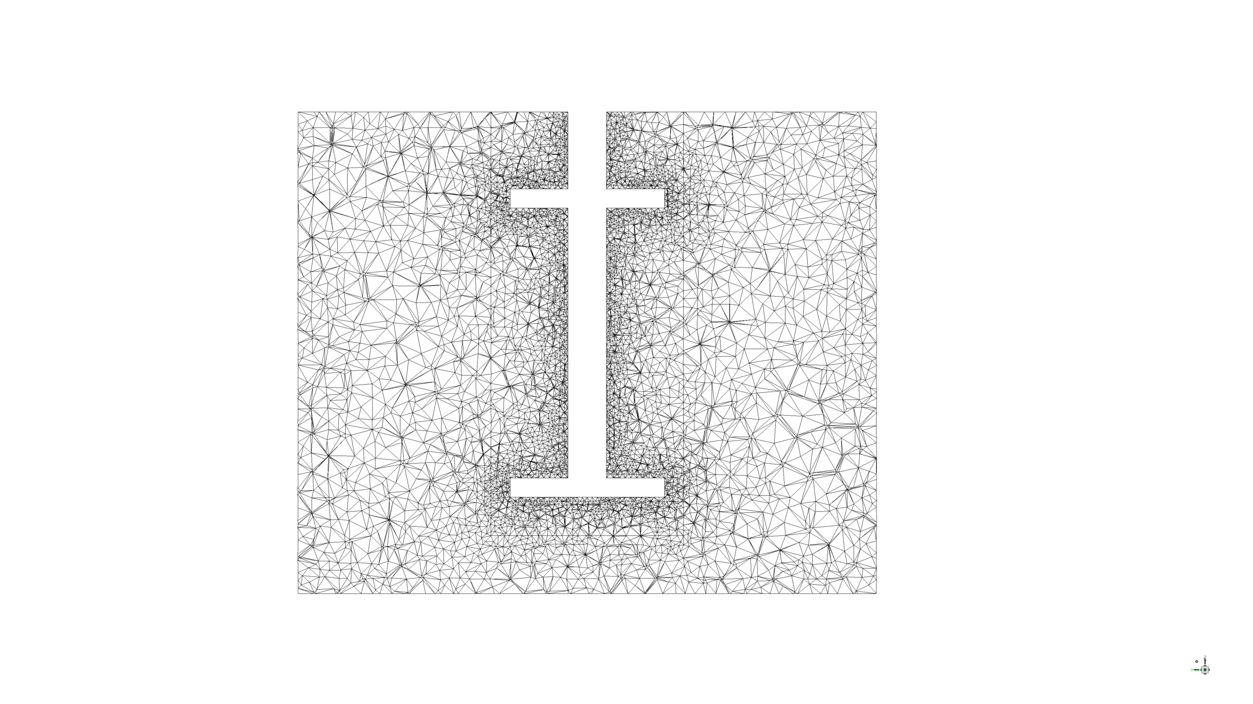
- We design the 3-D model by the Design Modeler and create the mesh using ANSYS Meshing software.
- The element number equals 229,177.
- The Frame Motion (MRF) option is enabled to define the rotational motion of the impellers.
To Order Your Project or benefit from a CFD consultation, contact our experts via email (info@mr-cfd.com), online support tab, or WhatsApp at +44 7443 197273.
There are some Free Products to check our service quality.
If you want the training video in another language instead of English, ask it via info@mr-cfd.com after you buy the product.
Description
Description
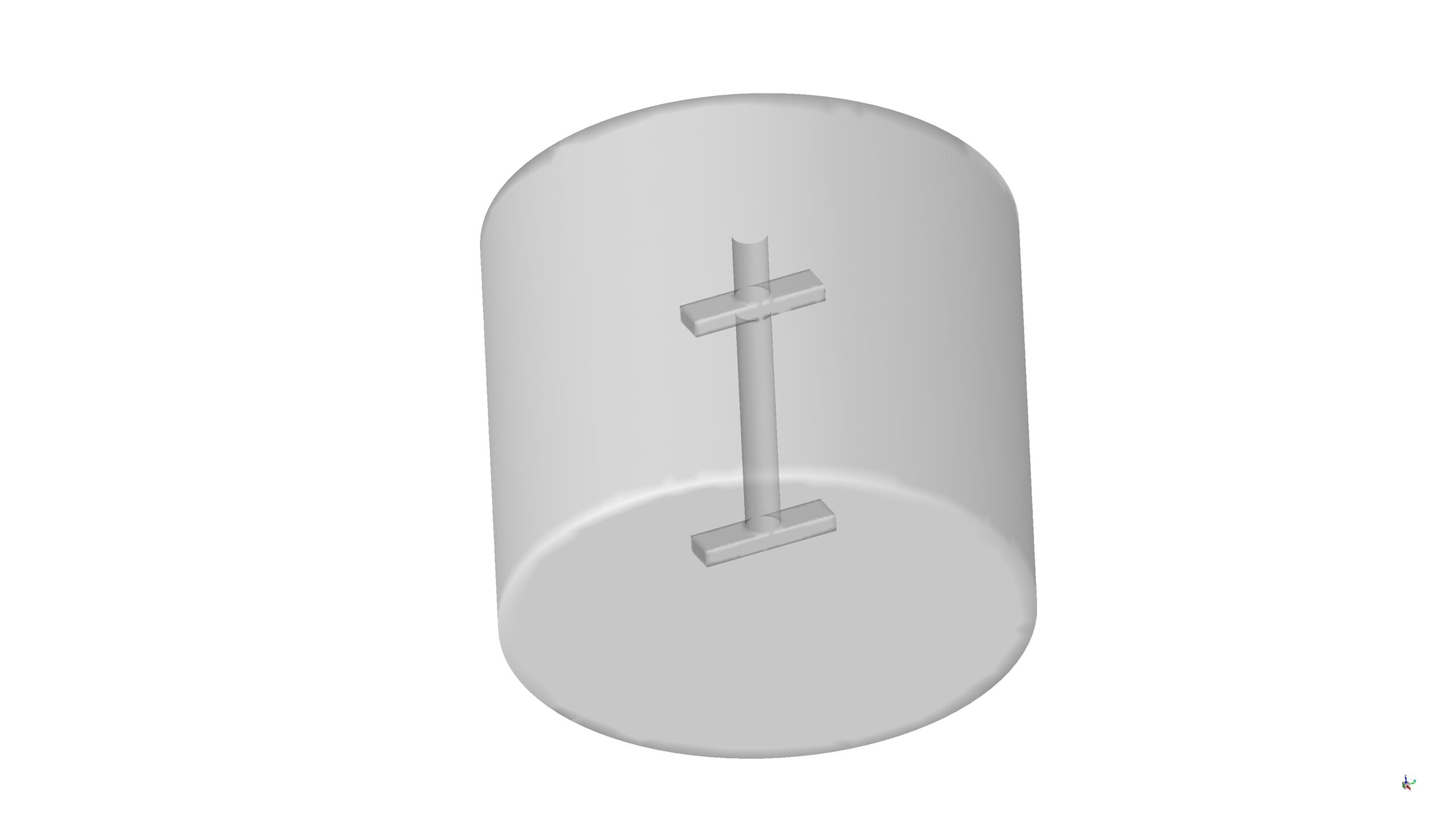
The present problem simulates the performance of a mixing tank by ANSYS Fluent software.
The closed mixing tank contains water liquid while the impeller starts rotating with 500 rev/min angular velocity, creating a massive vortex in the middle of the tank.
The geometry of the present model is three-dimensional and has been designed using Design Modeler software. We do the meshing of the present model by ANSYS Meshing software. The mesh type is unstructured, and the element number is 229,177.
This product is the 3rd episode of the Turbomachinery Training Course.
Methodology: Mixing Tank CFD Simulation by MRF Method
The Multiple Reference Frames (MRF) method is enabled to model the rotational movement of the impeller. In this method, two different zones without any interfaces should be created, and while the flow inside the rotating zone containing the impeller body rotates, the zone is stationary like other stationary zones.
The solution is Steady, and the k- Ꜫ model is chosen to simulate the turbulence of the flow.
Conclusion
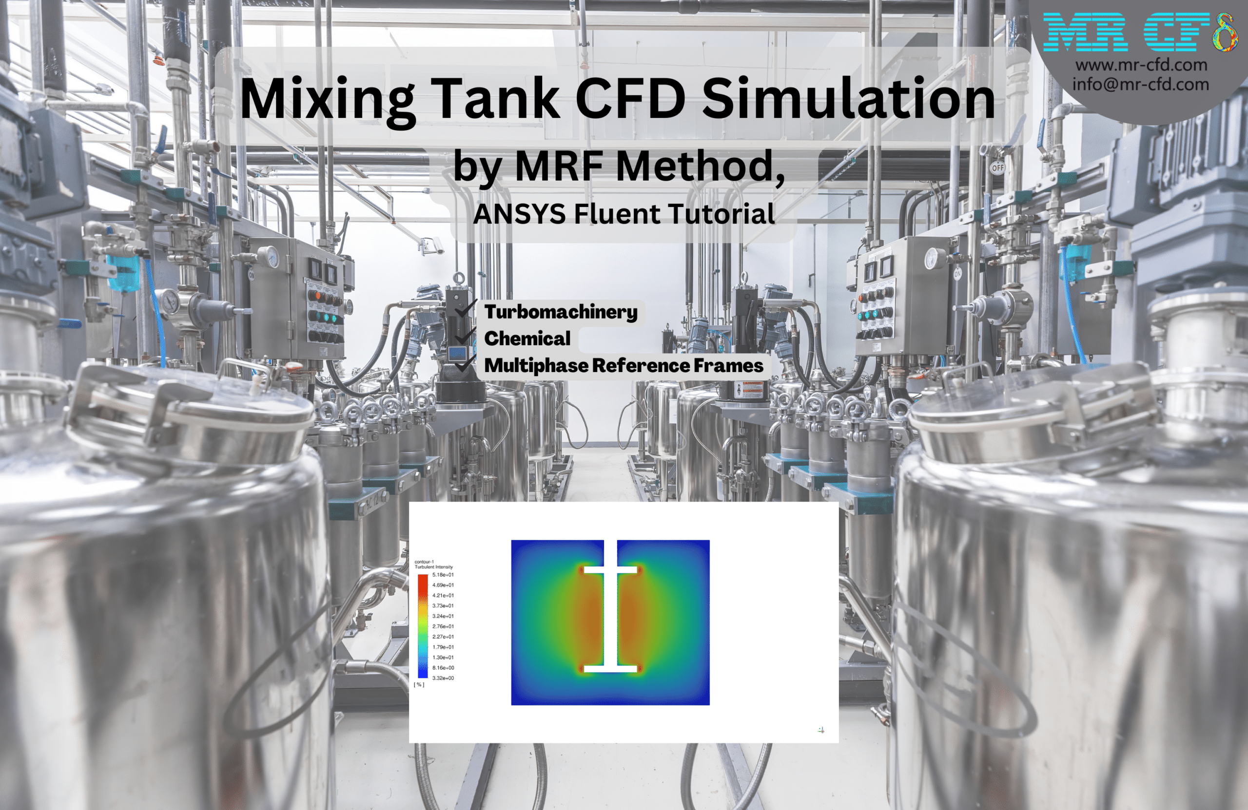
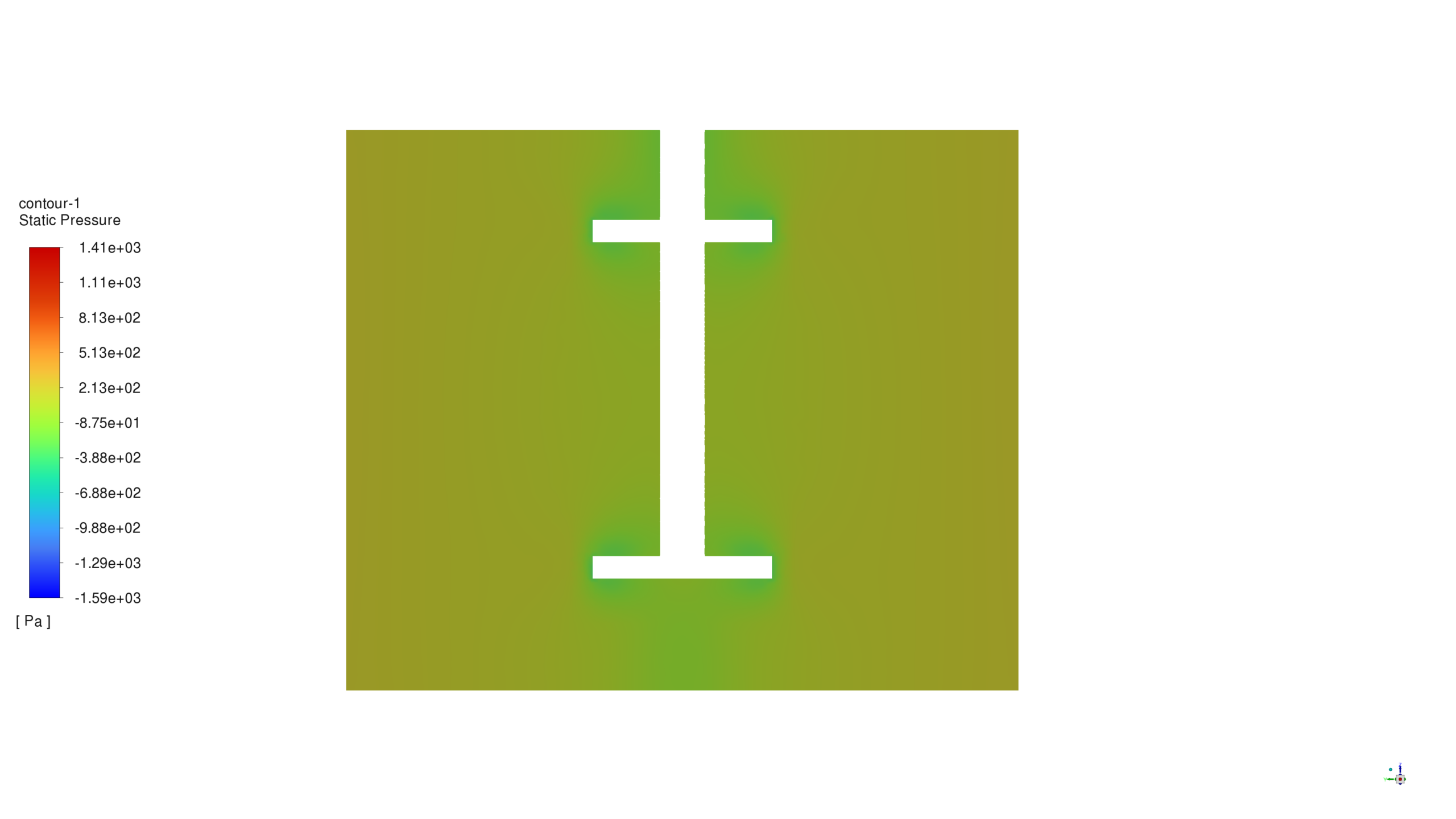
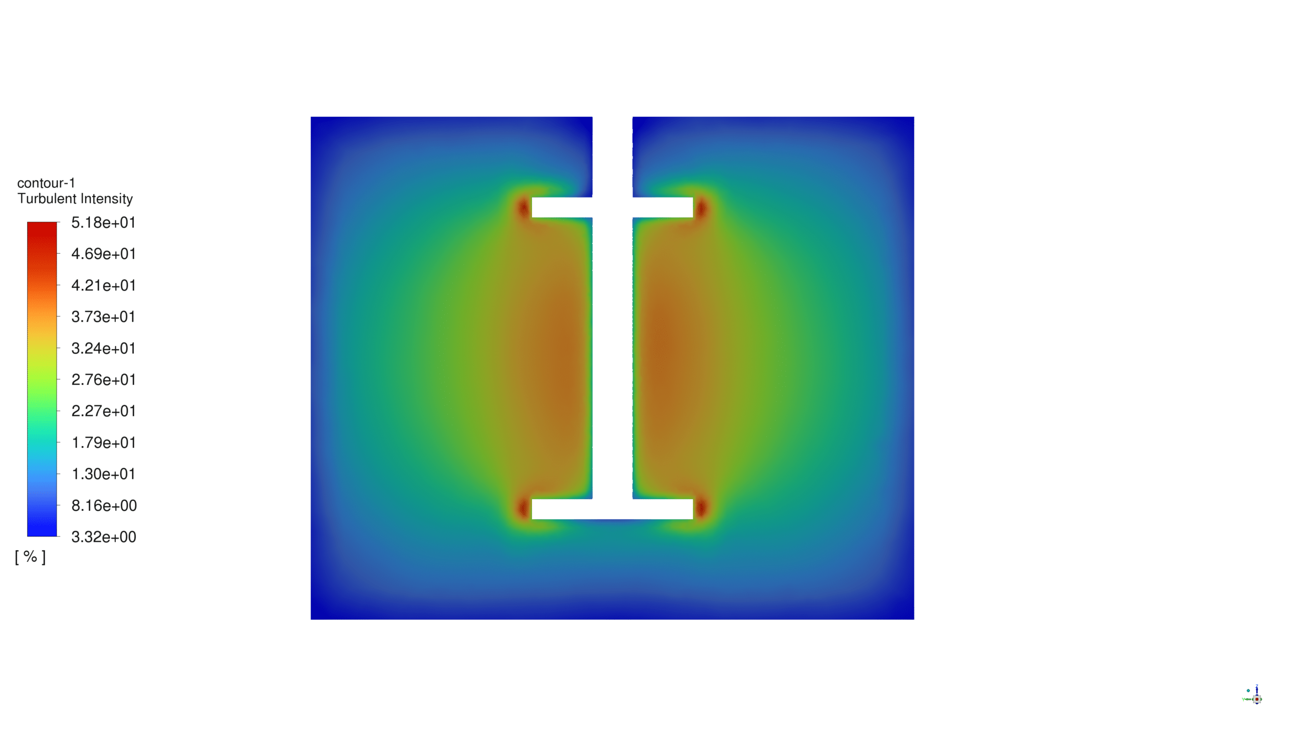
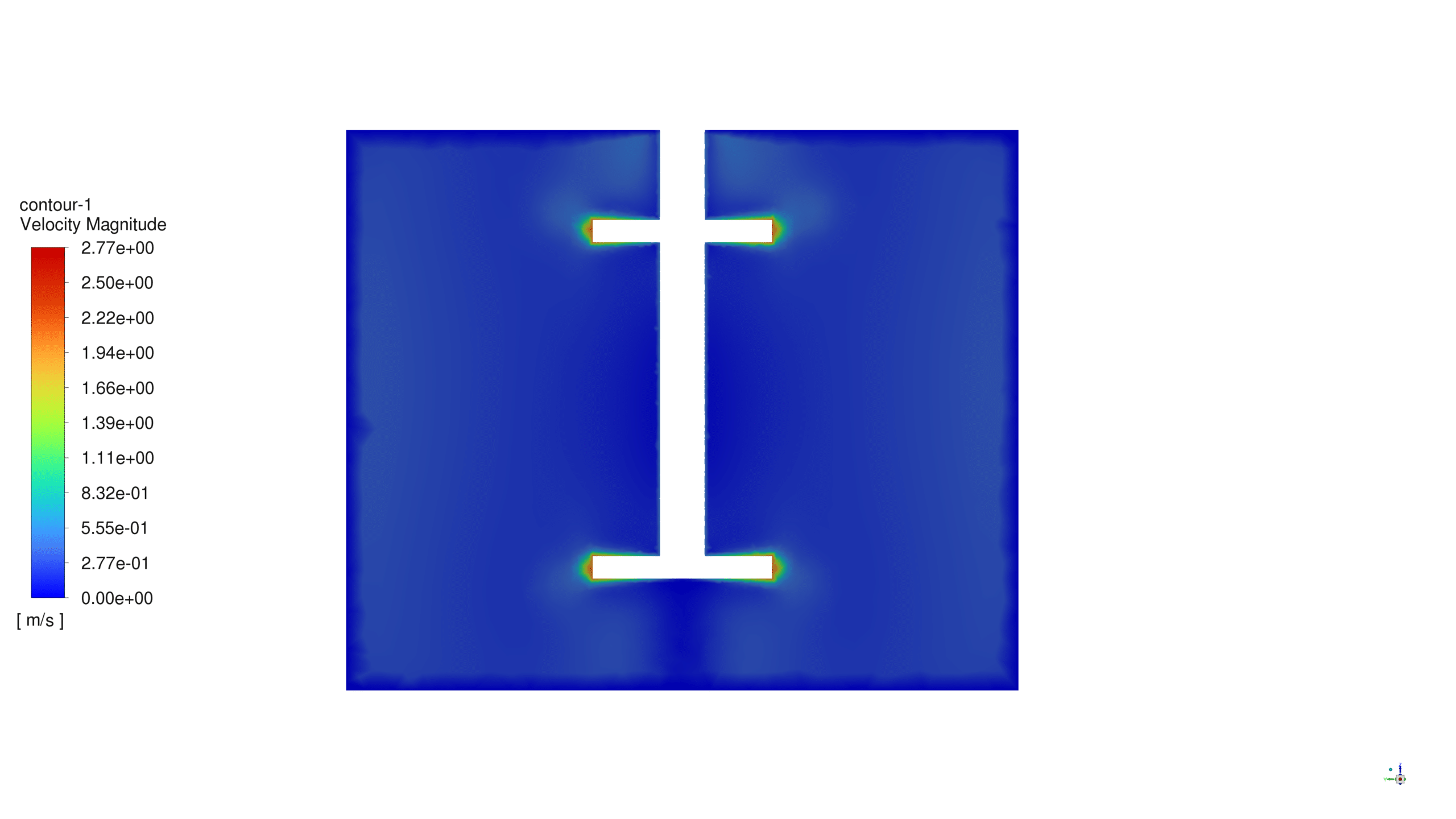
Since the main purpose of the issue is to investigate water movement inside a mixing tank, its related contours can be shown in the figures. Two-dimensional contours related to pressure, velocity, as well as turbulent intensity were obtained.
In the case of pressure, it is visible that the amount of water pressure in front of the impeller is much more than the amount behind it.
As was expected, the flow speed behind the impeller is more than in other areas in the domain. Also, the turbulent intensity parameter shows us the turbulence all over the tank, increasing by getting close to the impeller.
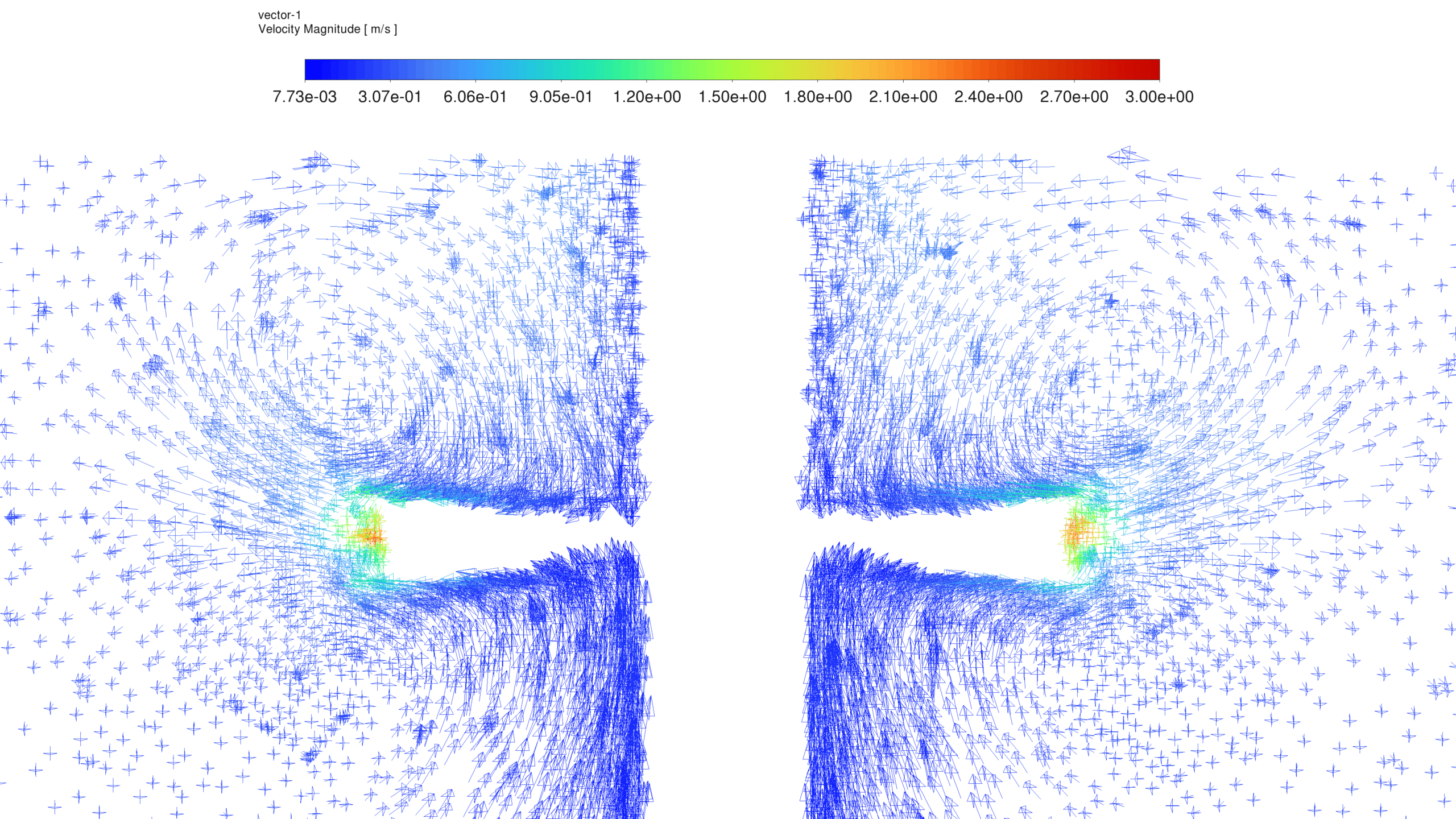
The vectors of the water around the impeller exactly show the vortexes around.



Reviews
There are no reviews yet.