Nanofluid Flow Heat Transfer in a Wave Sine Channel
$210.00 $105.00 Student Discount
The present problem simulates the wave motion of a nanofluid within a sinusoidal channel using ANSYS Fluent software.
Click on Add To Cart and obtain the Geometry file, Mesh file, and a Comprehensive ANSYS Fluent Training Video.To Order Your Project or benefit from a CFD consultation, contact our experts via email (info@mr-cfd.com), online support tab, or WhatsApp at +44 7443 197273.
There are some Free Products to check our service quality.
If you want the training video in another language instead of English, ask it via info@mr-cfd.com after you buy the product.
Description
Nanofluid Flow in a Wave Sine Channel, Heat Transfer Analysis, ANSYS Fluent CFD Simulation Training
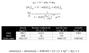
The present problem simulates the wave motion of a nanofluid within a sinusoidal channel using ANSYS Fluent software. The nanofluid current in the channel is defined as Al2O3-water; So it has nanoparticles with a volume fraction of 1%. According to the following equations, the thermophysical properties of the nanofluid material are obtained, and the amount of thermophysical properties of water fluid and nanoparticles is defined according to the data in the table below. The nanofluid flow enters the channel at a temperature of 300 K; due to the wavy structure of the geometry, the value of the horizontal velocity of the input current is a function of the vertical direction. This horizontal flow velocity function is defined as follows and is compiled into the software as a UDF.
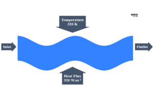
Also, in terms of thermal boundary conditions, the lower wall of the channel has a constant heat flux equal to 320 W.m-2, and the upper wall of the channel has a constant temperature equal to 320 K.
Geometry & Mesh
The current model is designed in two dimensions using Design Modeler software. The present model is a two-dimensional channel with sinusoidal walls. The canal length is equal to 4 m, and its width is equal to 1 m. So that its wavelength is equal to 2 m, and the height of each peak or bottom is equal to 0.4 m.
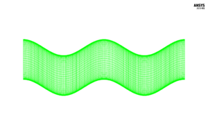
We carry out the model’s meshing using ANSYS Meshing software. The mesh type is structured. The element number is 21,300. The following figure shows the mesh.
Nanofluid CFD Simulation
We consider several assumptions to simulate the present model:
- We perform a pressure-based solver.
- The simulation is steady.
- The gravity effect on the fluid is ignored.
The following table represents a summary of the defining steps of the problem and its solution:
| Models | ||
| Viscous | Laminar | |
| Energy | On | |
| Boundary conditions | ||
| Inlet | Velocity Inlet | |
| velocity magnitude | UDF | |
| temperature | 300 K | |
| Outlet | Pressure Outlet | |
| gauge pressure | 0 pascal | |
| Up Wall | Wall | |
| wall motion | stationary wall | |
| Temperature | 320 K | |
| Down Wall | Wall | |
| wall motion | stationary wall | |
| Heat Flux | 320 W.m-2 | |
| Methods | ||
| Pressure-Velocity Coupling | Coupled | |
| pressure | second order | |
| momentum | second-order upwind | |
| energy | second-order upwind | |
| Initialization | ||
| Initialization methods | Standard | |
| gauge pressure | 0 pascal | |
| x-velocity | 0.0015 m.s-1 | |
| y-velocity | 0 m.s-1 | |
| temperature | 300 K | |
Nanofluid Results
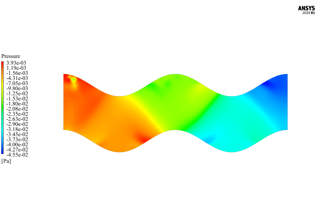
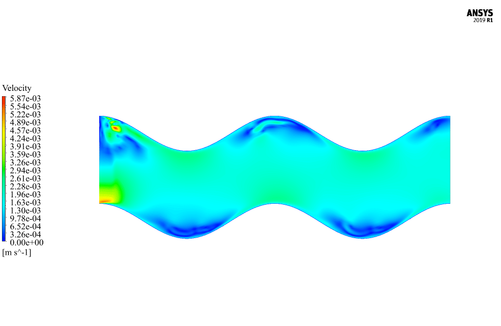
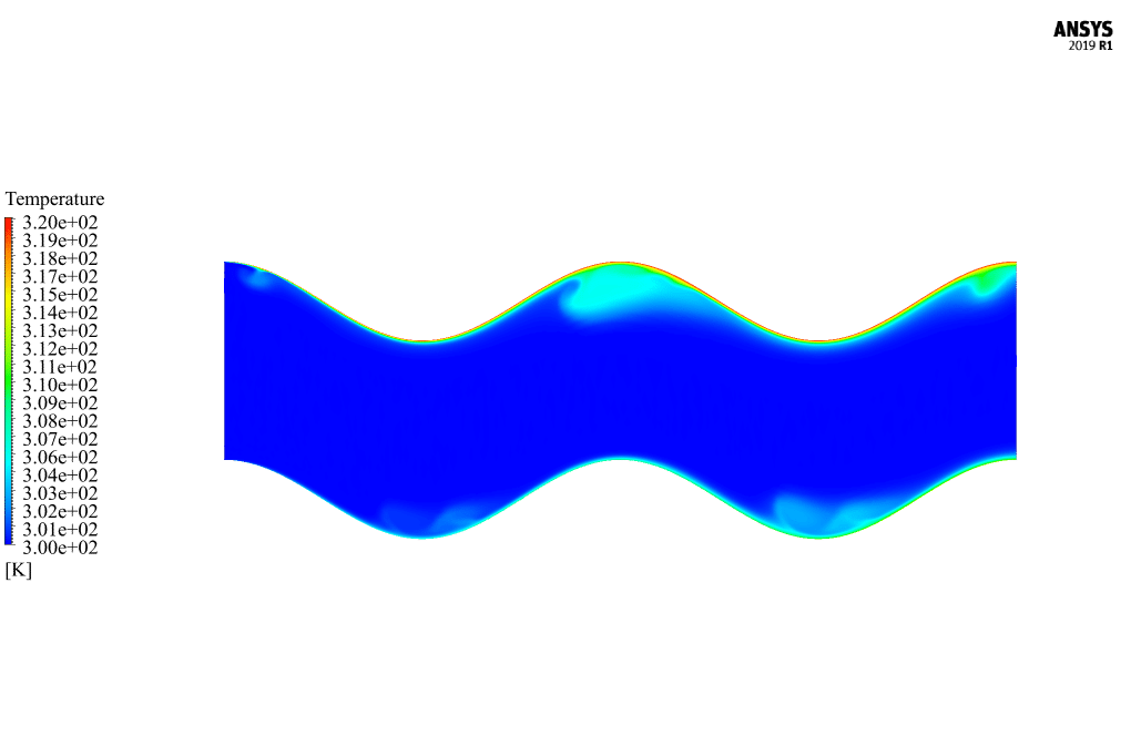
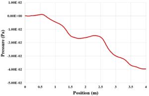
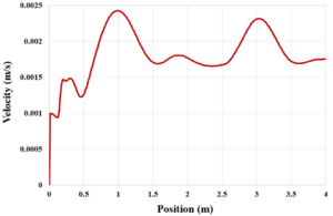
At the end of the solution process, two-dimensional contours related to temperature, pressure, and velocity are obtained. The graph of pressure and velocity changes along a hypothetical horizontal line passing through the middle of the channel is also obtained.

Reviews
There are no reviews yet.