Northrop Grumman RQ-4 Global Hawk Analysis CFD Simulation, ANSYS Fluent
$60.00 $30.00 Student Discount
- This study aims to investigate the aerodynamic performance of a Grumman RQ-4 Global Hawk using ANSYS Fluent.
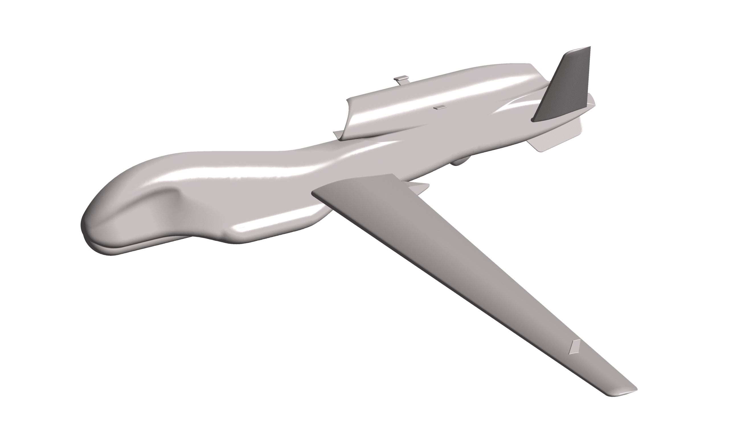
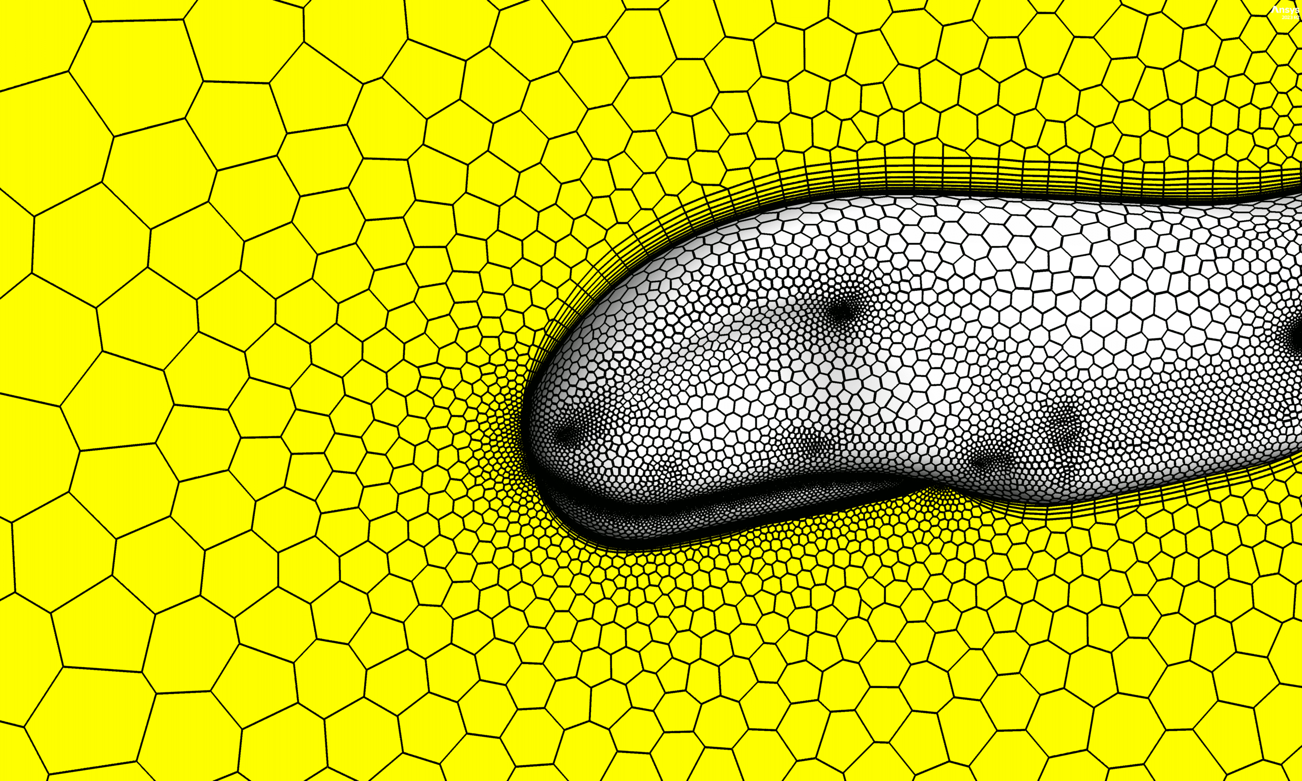
- The Global Hawk geometry was modelled using SpaceClaim then imported into ANSYS Fluent for meshing consisting 3,764,695 elements.
- The simulation used a pressure-based solver.
To Order Your Project or benefit from a CFD consultation, contact our experts via email (info@mr-cfd.com), online support tab, or WhatsApp at +44 7443 197273.
There are some Free Products to check our service quality.
If you want the training video in another language instead of English, ask it via info@mr-cfd.com after you buy the product.
Description
Description
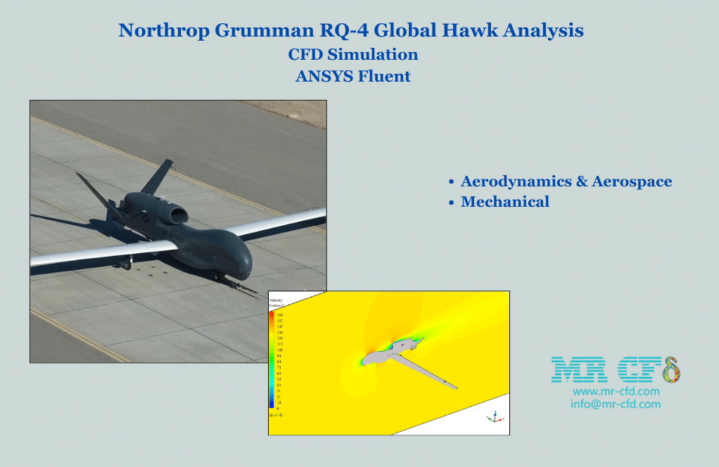
This product presents a comprehensive CFD analysis of the Northrop Grumman RQ-4 Global Hawk, a high-altitude, long-endurance crewless aerial vehicle (UAV). The study aims to investigate the aerodynamic performance and flow characteristics around the UAV using ANSYS Fluent, a powerful CFD software.
Geometry and Mesh Generation:
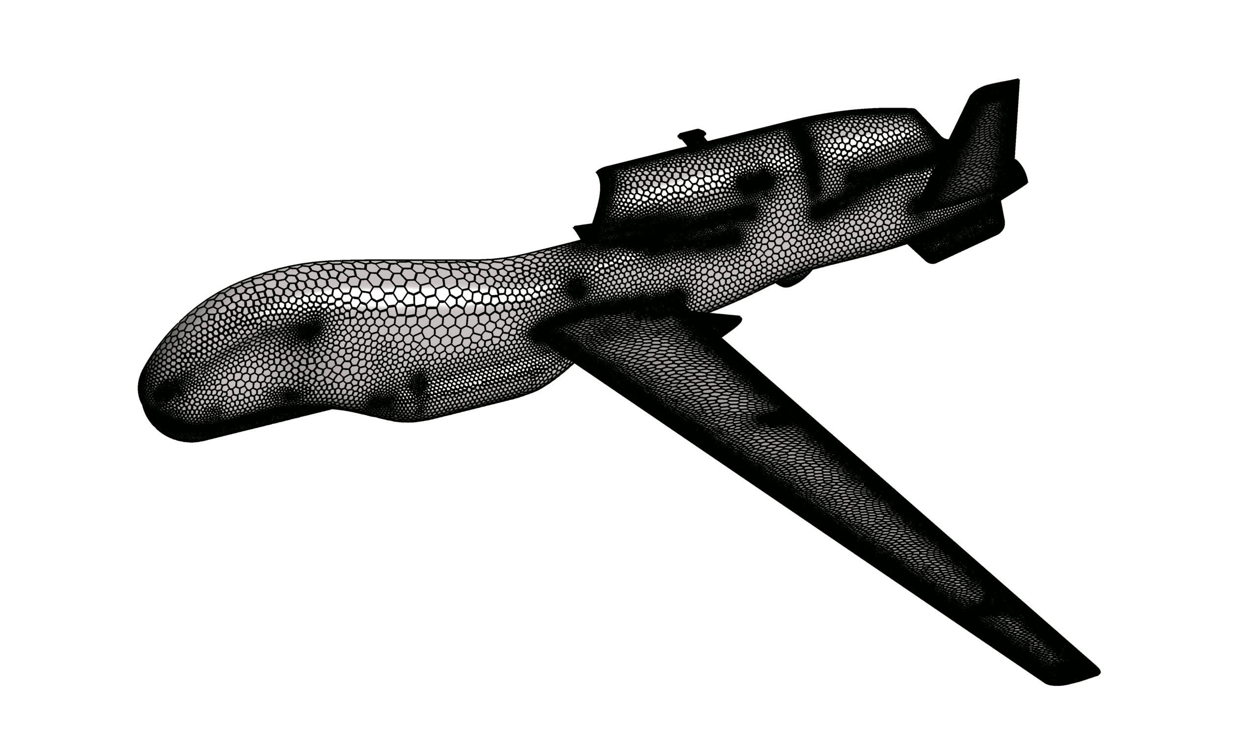
The Global Hawk geometry was modelled using SpaceClaim, a 3D modelling software integrated with ANSYS. The model was then imported into ANSYS Fluent for meshing. A boundary layer with ten rows was employed to accurately capture the near-wall flow phenomena. The mesh generated consists of 3,764,695 elements with a minimum orthogonality of approximately 0.18, ensuring a high-quality mesh for accurate flow simulations.
also You can view the FSI and wing LIft-to-Drag Ratio optimization with RBF-morph.
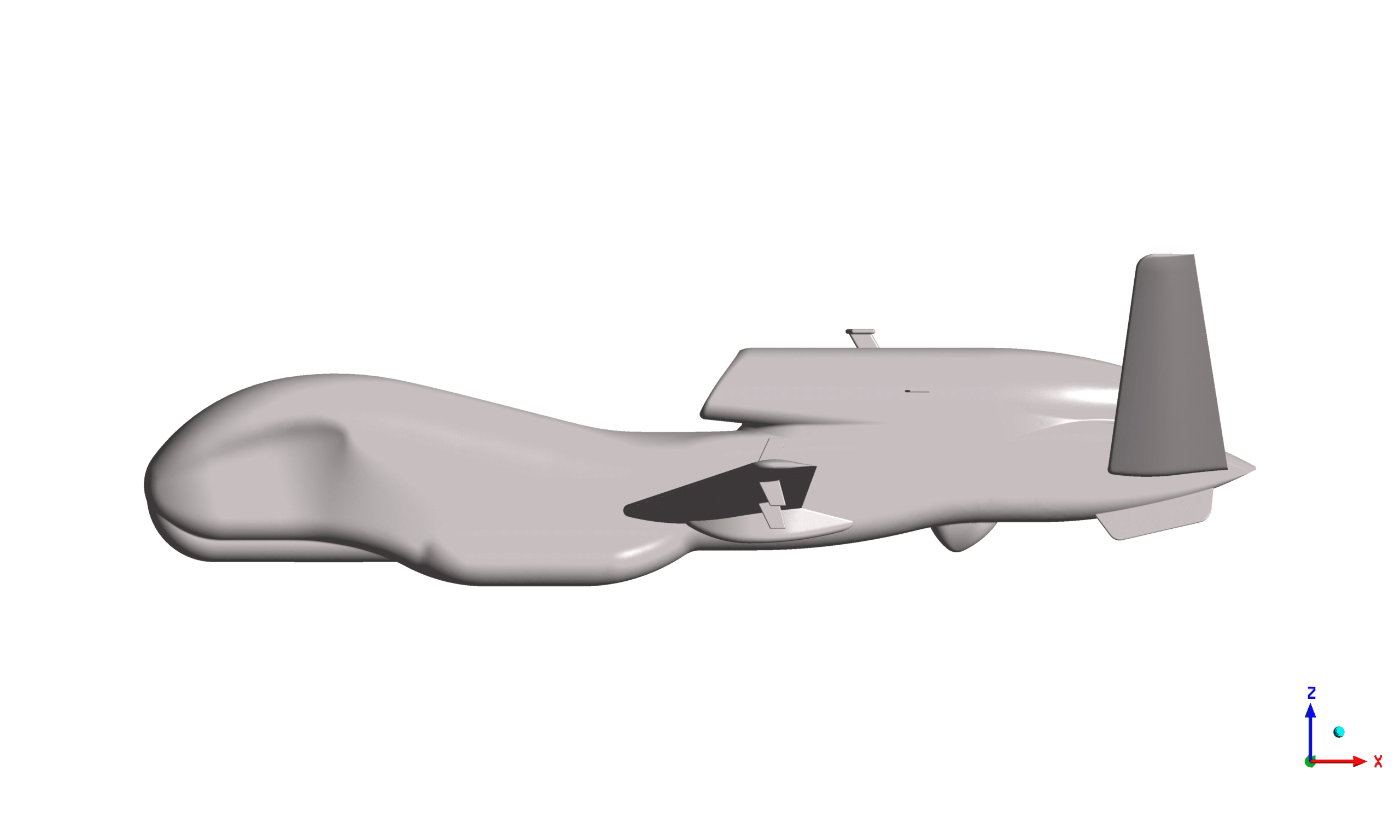
Figure1: Geometry
Figure2: Mesh
Boundary Conditions and Solver Settings:
The simulation used a pressure-based solver, considering air an ideal gas and the problem is solved in symmetric mode. The UAV surface was modelled as a wall with a no-slip condition. The inlet and far-field boundaries were set as pressure far-field with a Mach number of 0.39 and an angle of attack of 5 degrees, representing the UAV’s operating conditions. The SIMPLE algorithm was used for pressure-velocity coupling, and the solution was initialized using standard initialization.
Results and Discussion:
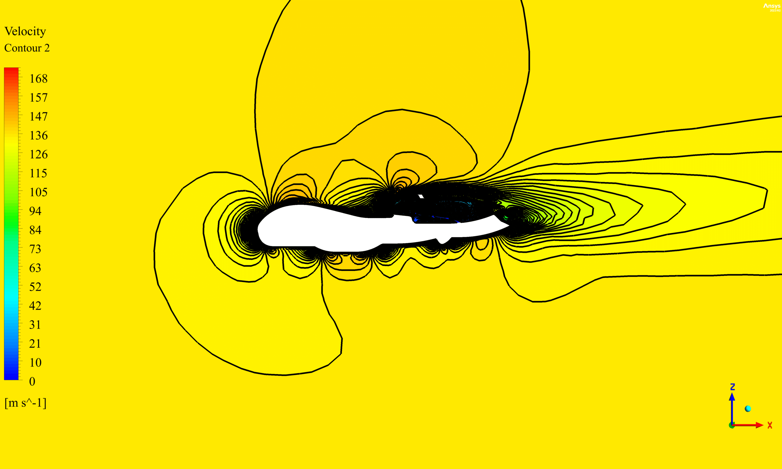
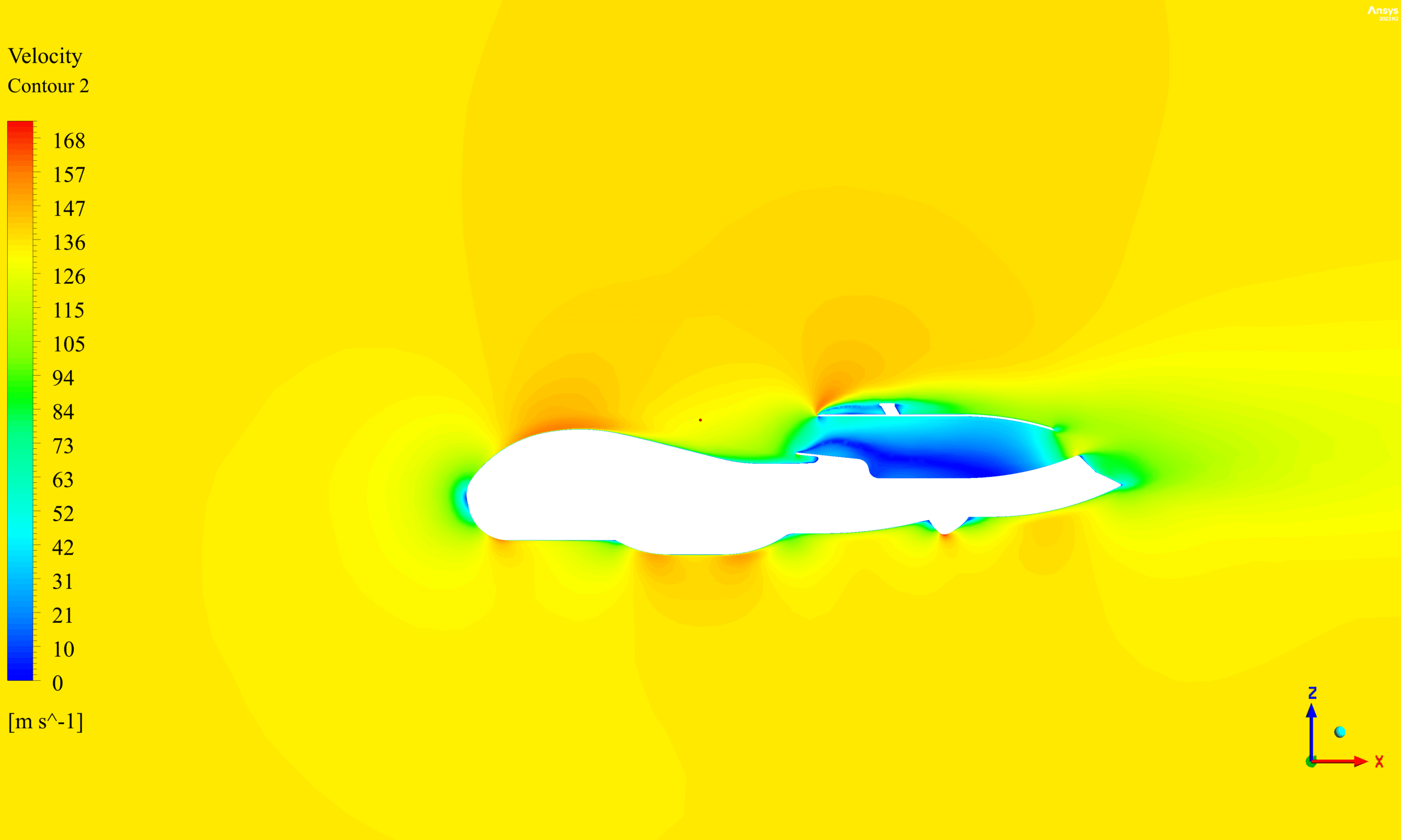
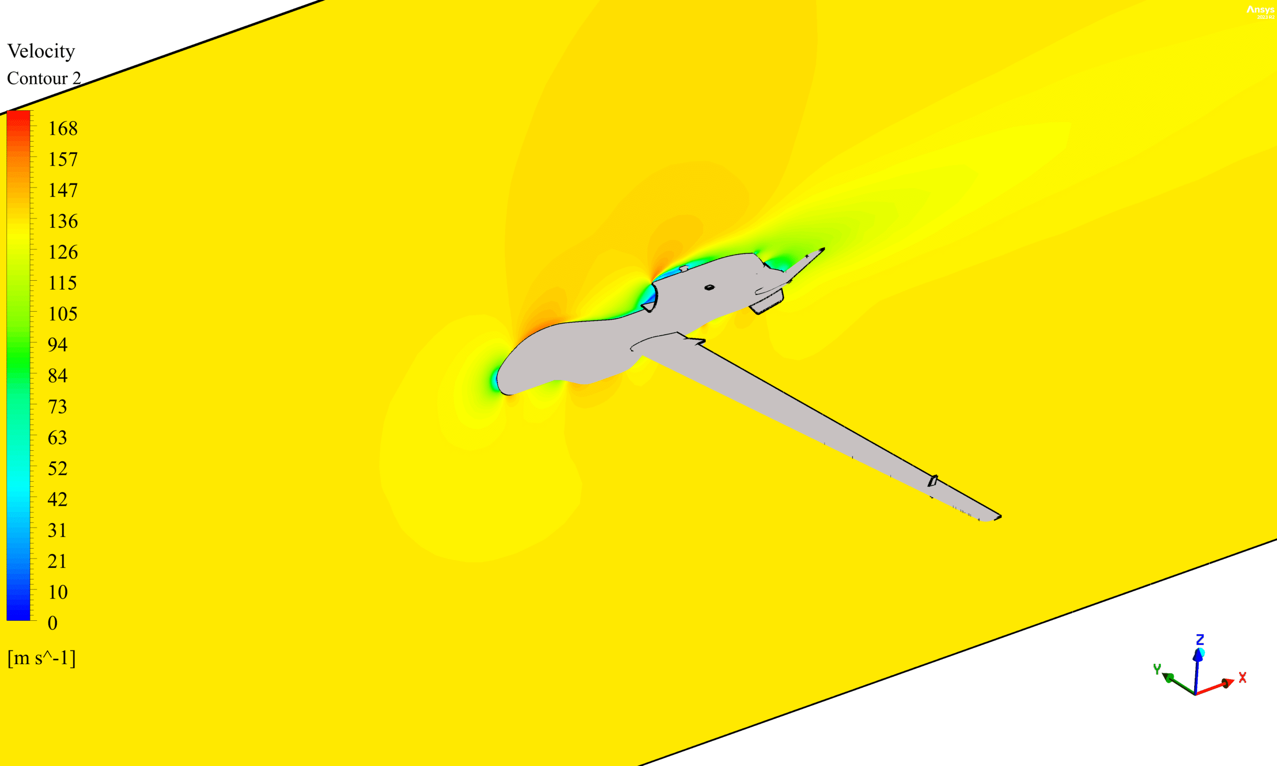
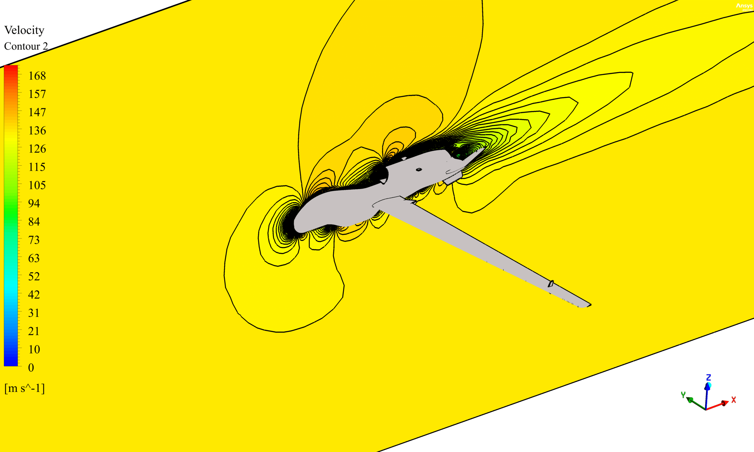
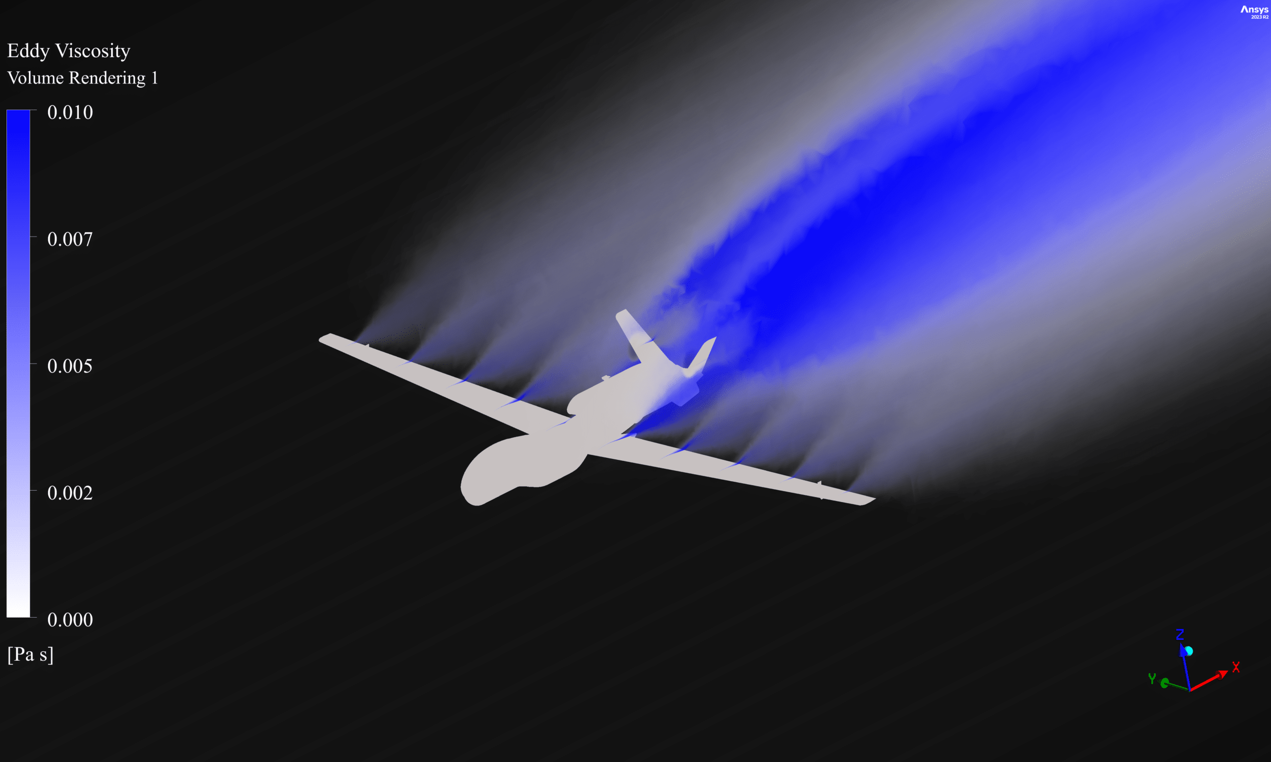
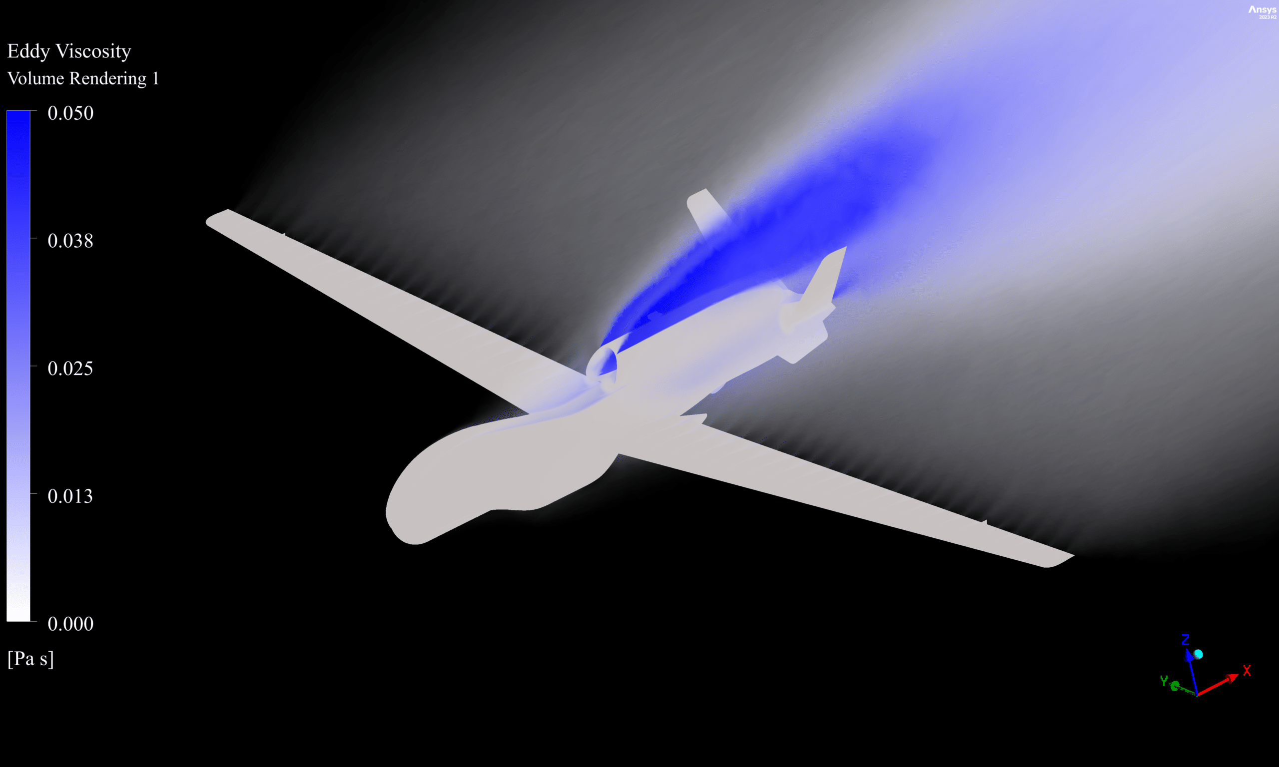
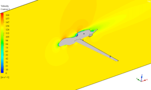
The velocity contours indicated the formation of boundary layers and wake regions behind the UAV. The streamlines depicted the flow path around the Global Hawk, highlighting any flow separation or vortex formations. The eddy viscosity contours provided information about the turbulence levels in the flow field.
Figure3: Velocity couture
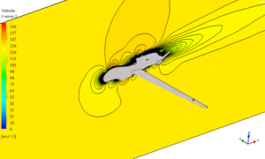
The CFD simulation provided valuable insights into the aerodynamic performance of the Global Hawk. The pressure contours obtained from CFD-Post, ANSYS’s post-processing tool, revealed the pressure distribution around the UAV. As observed in Figure 4, the pressure is higher on the wing’s lower surface and lower on the upper surface. This pressure difference is essential for generating lift, creating a net upward force on the wing. The higher pressure on the lower surface results from the air being compressed as it flows over the wing’s leading edge, while the lower pressure on the upper surface is due to the faster-moving air, as per Bernoulli’s principle.
View from below
View from above
Figure4: Pressure couture
Figure 5 depicts the pressure coefficient plot along the -14m plane. The plot clearly shows the high-pressure region near the leading edge of the wing, where the velocity approaches zero, and the pressure increases significantly. This phenomenon is consistent with the principles of fluid dynamics, as the air decelerates rapidly near the stagnation point at the leading edge, resulting in high pressure.
Figures 6 and 7 present the pressure and velocity contours on the -14m plane, respectively. The pressure contour (Figure 6) confirms the high-pressure region near the leading edge, as observed in the pressure coefficient plot. The velocity contour (Figure 7) illustrates the flow behavior, with the velocity approaching zero near the leading edge and increasing as the flow moves along the wing’s surface.
The pressure distribution observed in the figures, with higher pressure on the lower wing surface and lower pressure on the upper surface, is crucial for generating lift and is consistent with the principles of aerodynamics.
Figure 5: plot of pressure coefficient in -14m plan
Figure 6: pressure couture in -14m plan
Figure 7: velocity couture in -14m plan
Quantitative data, such as lift and drag forces, were obtained from the simulation. The drag force was found to be 47,515.528 N, while the lift force was 199,109.67 N. These values provide essential information about the Global Hawk’s aerodynamic performance and can be used for further analysis and design optimization.
Conclusion:
The CFD analysis of the Northrop Grumman RQ-4 Global Hawk using ANSYS Fluent provided valuable insights into its aerodynamic characteristics. The high-quality mesh with ten rows of boundary layer elements, appropriate boundary conditions, and solver settings ensured accurate and reliable results. The pressure, velocity, and eddy viscosity contours and streamlines offered a comprehensive understanding of the flow behavior around the UAV at a 5-degree angle of attack.
The pressure coefficient plot and contours extracted from the -14m plane clearly demonstrate the high-pressure region near the leading edge, where the velocity approaches zero. This phenomenon is consistent with fluid dynamics principles and contributes to the overall lift generation.
The pressure distribution observed in Figure 4, with higher pressure on the lower wing surface and lower pressure on the upper surface, is crucial for generating lift and is consistent with the principles of aerodynamics.
The obtained lift and drag forces, 199,109.67 N and 47,515.528 N, respectively, quantify the aerodynamic performance of the Global Hawk under the given operating conditions. These values can be used as a reference for future design modifications and optimizations.
This study demonstrates the effectiveness of CFD in analyzing complex aerodynamic problems and its potential for design optimization. Further investigations can be conducted to explore the effects of different operating conditions, design modifications, or flow control techniques on the Global Hawk’s performance.
The results obtained from this CFD analysis can serve as a foundation for future studies and contribute to the ongoing development and improvement of high-altitude, long-endurance UAVs like the Northrop Grumman RQ-4 Global Hawk.





Reviews
There are no reviews yet.