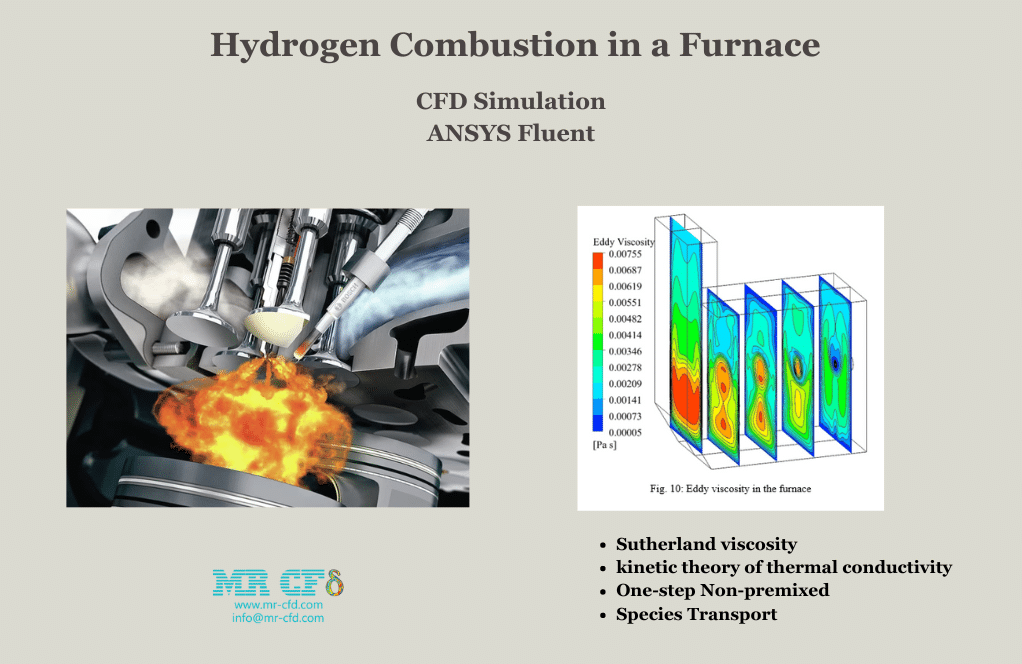
Hydrogen Combustion in a Furnace CFD Simulation, ANSYS Fluent
$140.00 $70.00 Student Discount
- The problem numerically simulates one-step non-premixed hydrogen combustion with integration of the Sutherland viscosity and kinetic theory of thermal conductivity
using ANSYS Fluent software. - We design the 3-D model with the Spaceclaim software.
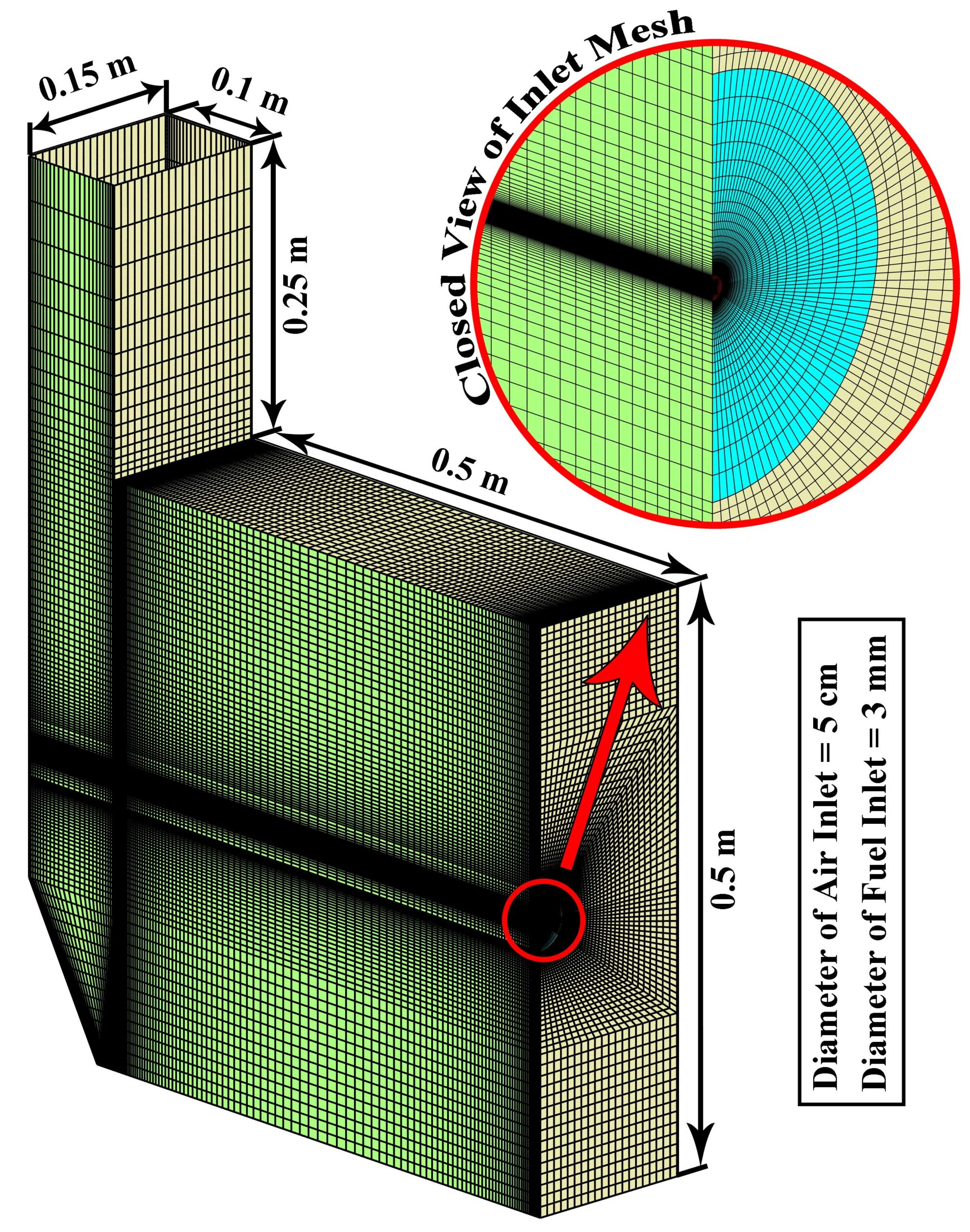
- We mesh the model with ANSYS Meshing software. The mesh type is Structured
- We use the Species Transport model to define a Combustion reaction.
- The combination of Sutherland viscosity and kinetic theory for thermal conductivity is presented for the accurate simulation of the combustion process.
- The standard k-e turbulence model is used to simulate the turbulence.
To Order Your Project or benefit from a CFD consultation, contact our experts via email (info@mr-cfd.com), online support tab, or WhatsApp at +44 7443 197273.
There are some Free Products to check our service quality.
If you want the training video in another language instead of English, ask it via info@mr-cfd.com after you buy the product.
Description
Hydrogen Combustion in a Furnace with Integration of the Sutherland viscosity and kinetic theory of thermal conductivity
Description
In recent decades, the numerical simulation of the combustion process has become one of the most important methods in the design of various systems. These modeling, if they have high accuracy, can provide many details of the complexity of the physicochemical process. Thus, when considering real issues such as pollution, ignition and extinction, the simulation method must be done accurately, so that reliable results can be obtained. The bulk viscosity is one such process to increase accuracy in simulation, that is produced by viscous forces that arise when a volume of fluid is compressed or dilated. Viscosity plays a major role in combustion in terms of fluid properties. In other words, the viscosity is one of the most important components of the coupling of turbulence and combustion. On the other hand, the kinetic theory of gases provides us with a relatively complementary framework for calculating the thermal conductivity in combustion problems. In this project, the combination of Sutherland viscosity and kinetic theory for thermal conductivity is presented for the accurate simulation of the combustion process. Therefore, the chemical reaction in the one-stage combustion of air/hydrogen has clearly shown the physical and chemical phenomena.
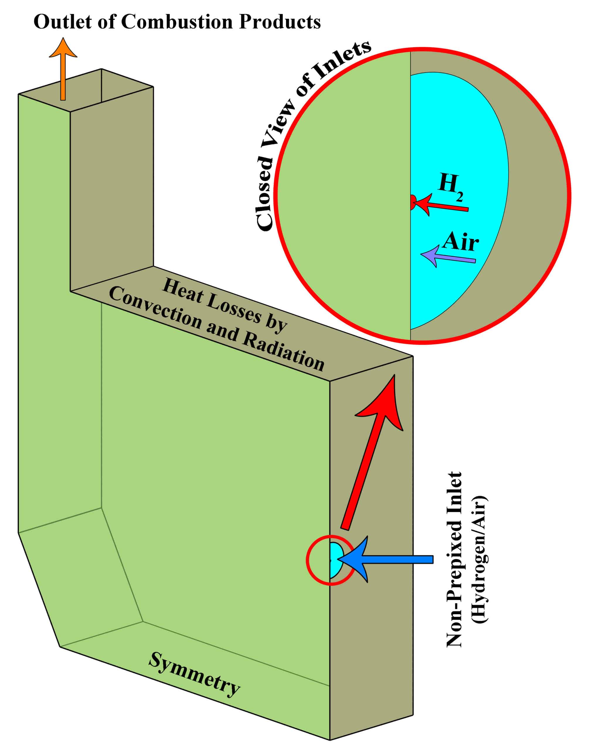
The design of a furnace with separate inlets of fuel and air is shown in the fig. 1. Inlet mass flow rate is set for hydrogen and air inlet, and for the outlet, the boundary condition of the outlet pressure and depletion to the atmosphere is considered. The mass flow rate is set to 0.01 Kg/s for air, and 0.0003 Kg/s for hydrogen, in which case the equivalence ratio is equal to 1. The boundary conditions of the side walls are all of the type of heat loss with the outside environment through convection and radiation (With the heat transfer coefficient of 16 W/m2/K, the ambient temperature is 300 K and the sky temperature is 271.2 K). Also, a thickness of 5 cm of shell condition type and steel metal is considered for the side walls.

 Results
The simulations are conducted in such a way that a non-premixed air-hydrogen mixture, with an equivalence ratio of 1, enters the furnace, and after the chemical reactions are completed, the combustion products are depletion to the atmosphere at the outlet. In this way, the properties of the non-premixed mixture, which is modeled by species transport, are given in the table 1.
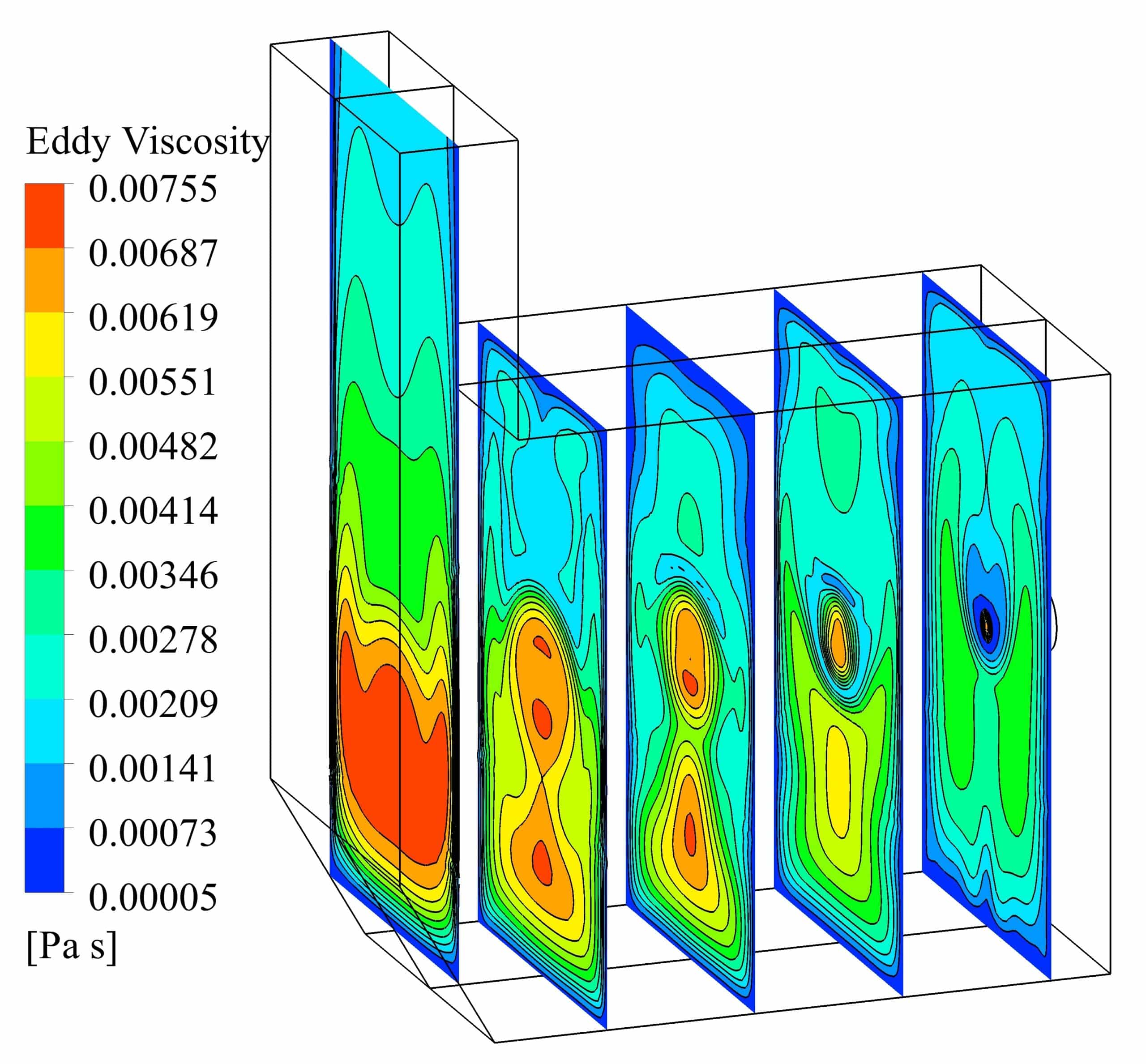
The standard k-e turbulence model is used to simulate the combustion process. The volumetric reaction has been performed by activating the diffusion of the energy source and the turbulence-chemistry interaction of the eddy dissipation type. The SIMPLE algorithm is used for pressure and velocity coupling in the solution method section. Least Squares Cell Based is also considered for discretization of gradients, Second Order for pressure and Second Order Upwind for other variables. The Under relaxation factors are arranged such that convergence has taken place to the desired extent.
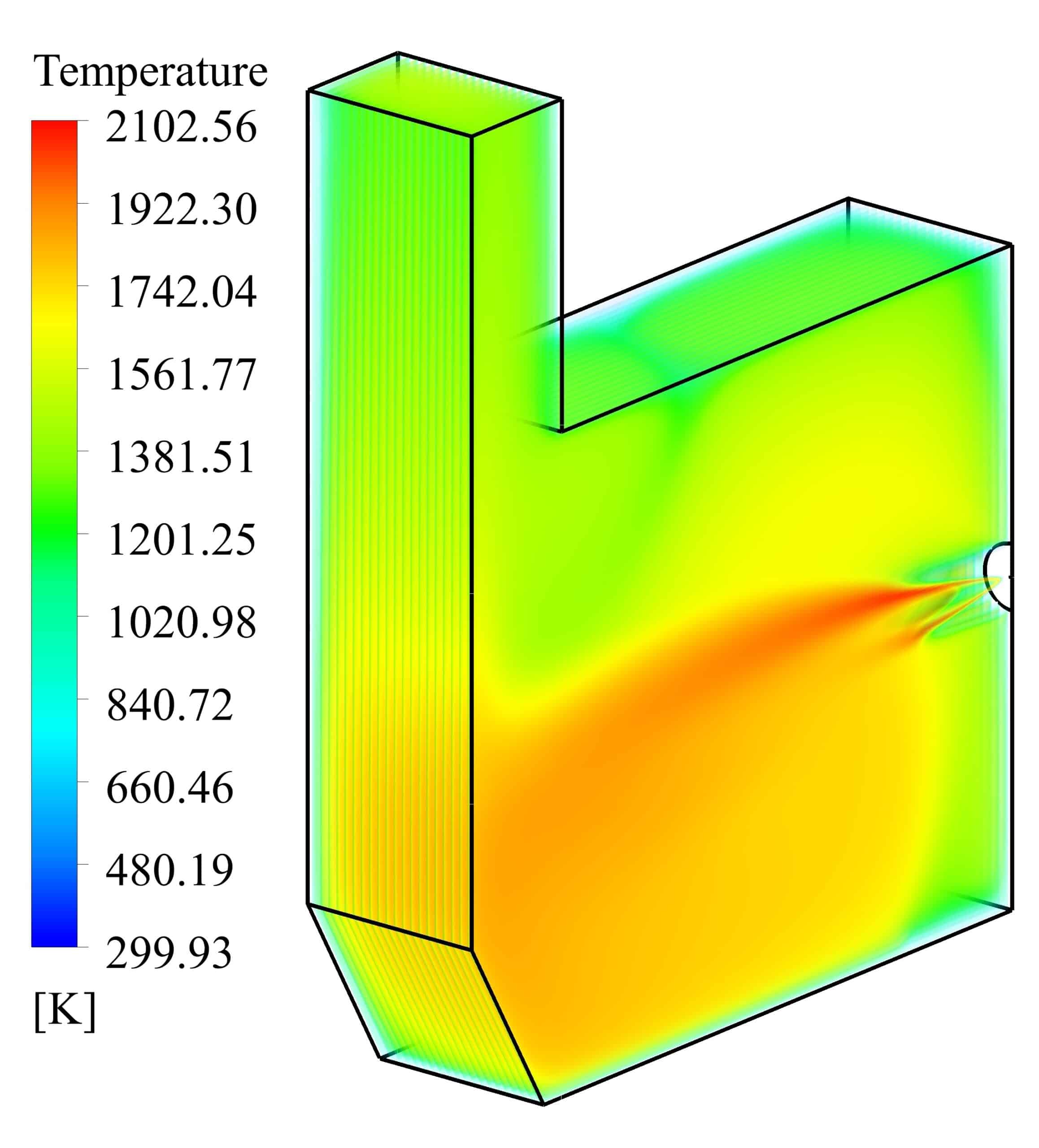
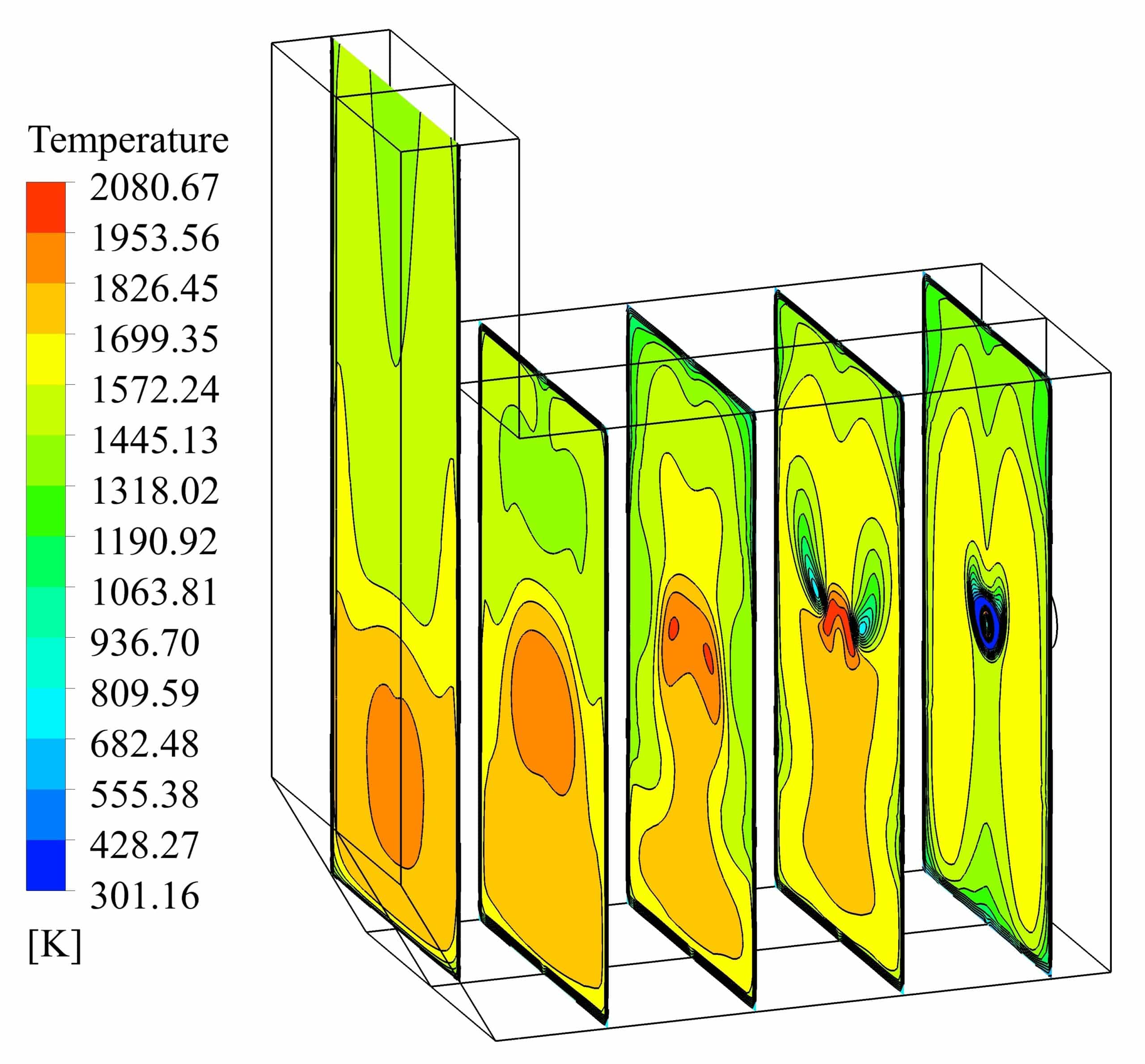
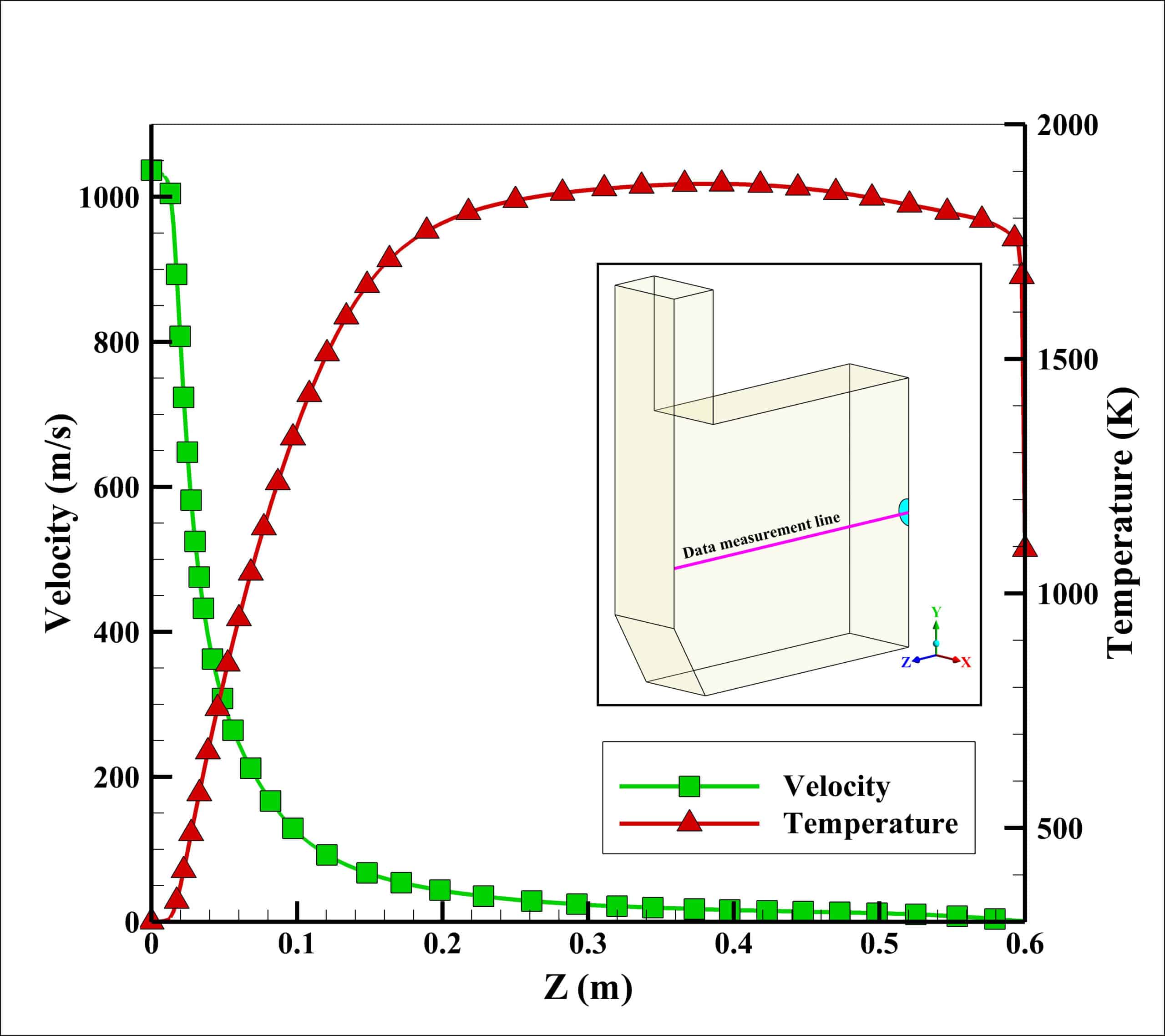
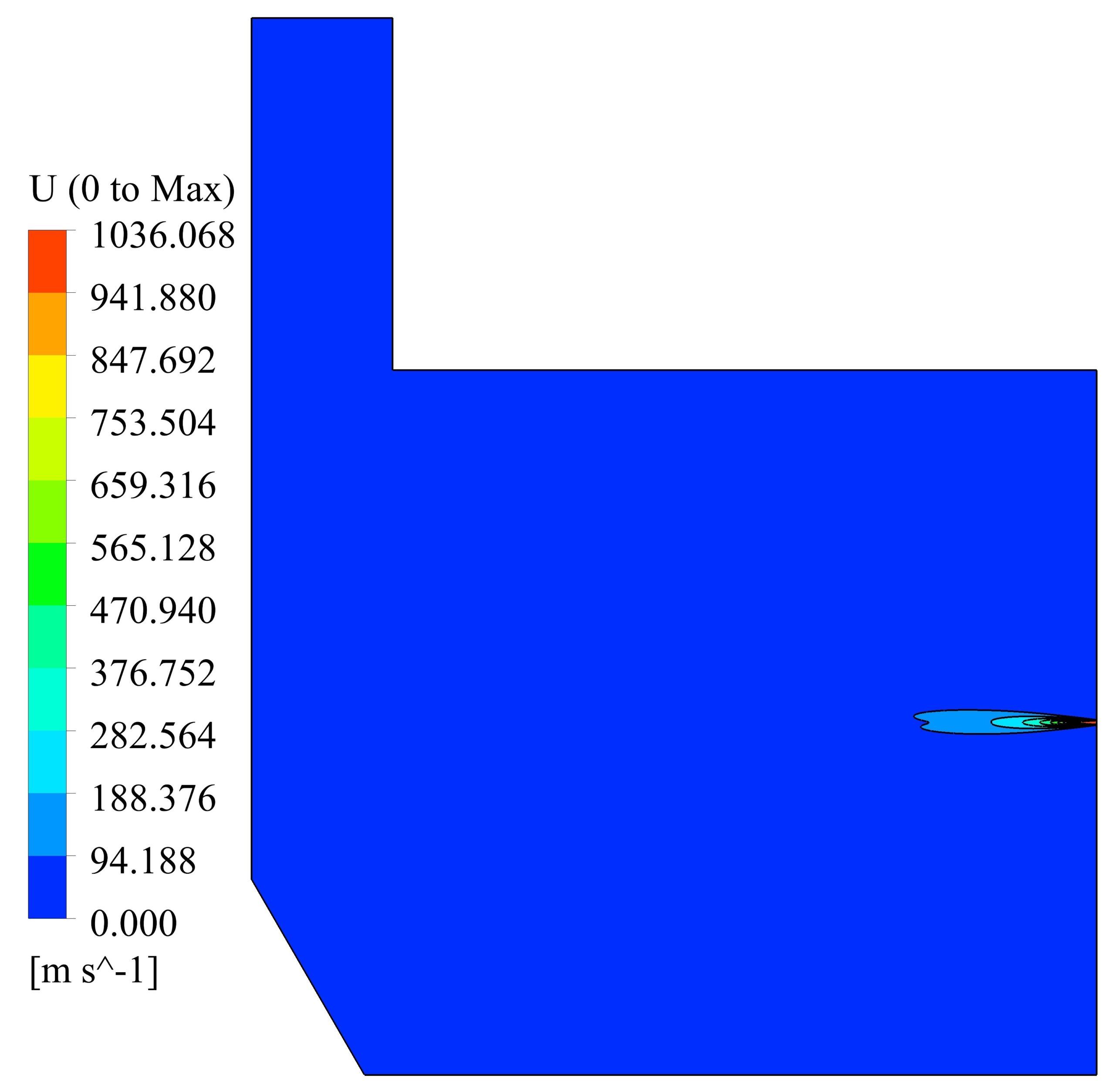
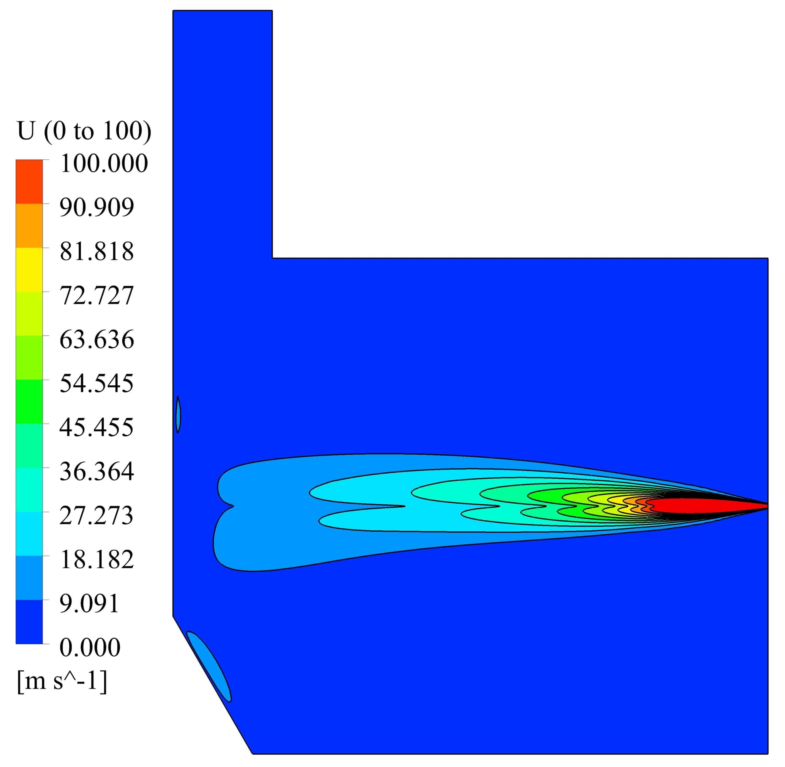
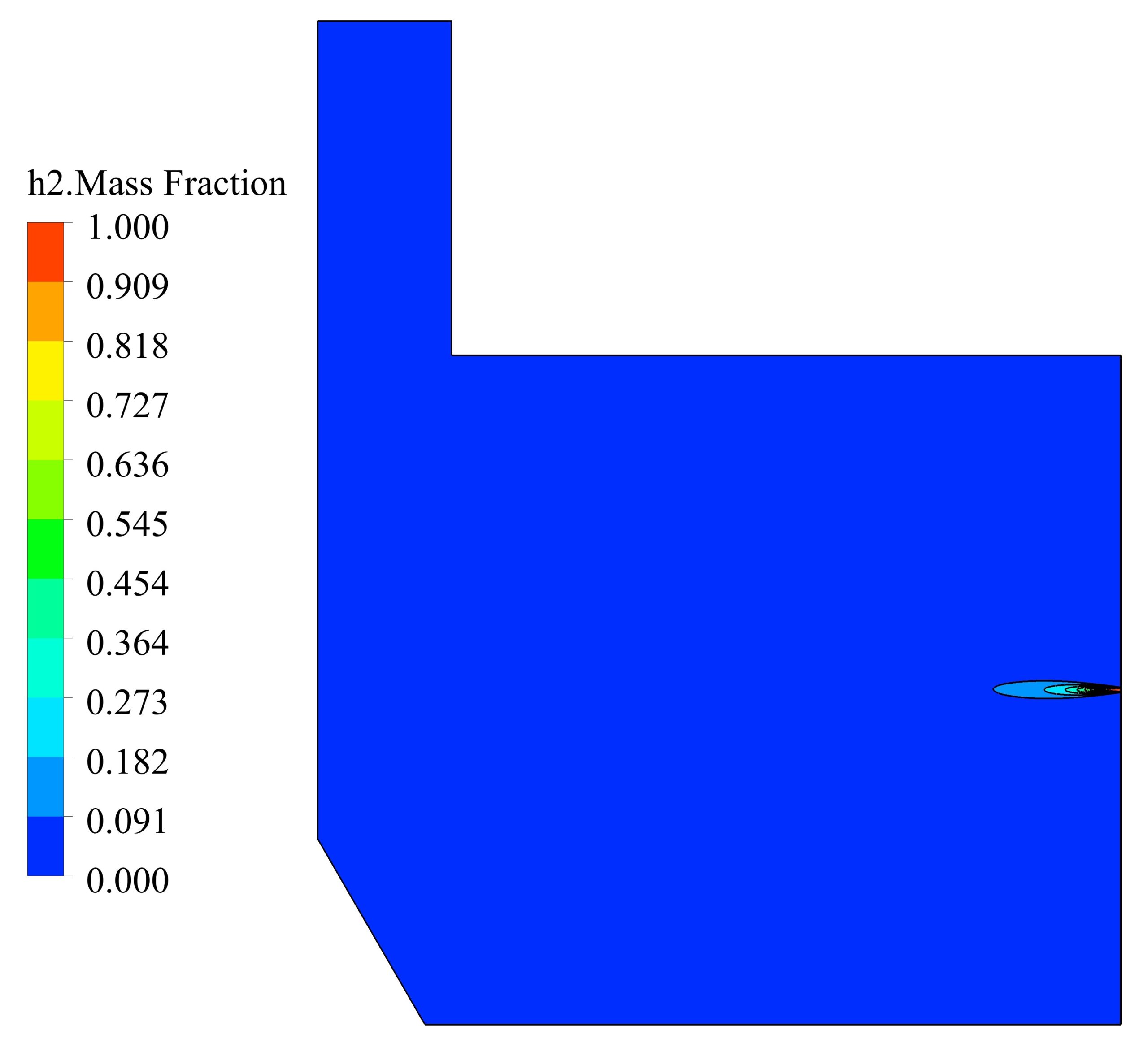
Velocity and temperature curves on the center line of fuel inlet are illustrated in Fig. 3. The maximum velocity was 1063 m/s at the fuel inlet, and the maximum temperature obtained 1860 K.

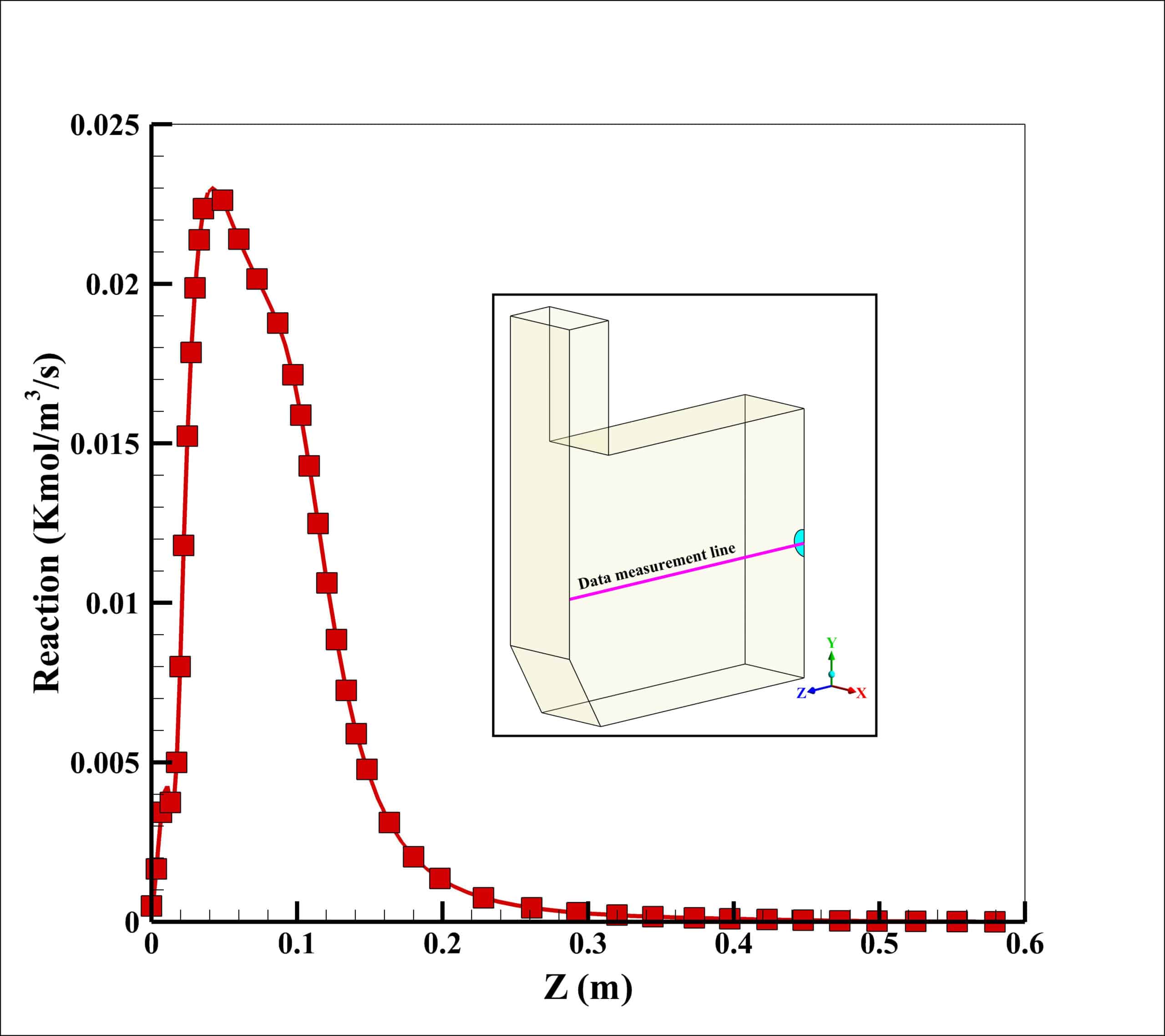
The maximum reaction rate also occurred at a distance of 2 cm from the entrance, which is 0.23 kmol/m3/s. After a distance of 0.4 meters, the reaction rate has reached zero, which indicates the completion of the flame.


Conclusion
In this project, non-premixed hydrogen/air combustion in a furnace with laboratory scale or even semi-industrial dimensions is modeled by the eddy dissipation method. The eddy dissipation method is based on the fact that the process of species transfer in chemical reactions is done quickly. Therefore, the reaction rate related to the timescales of turbulent is considered. If the chemical reaction of fuel and oxidant molecules takes place in a large space with atmospheric pressure(such as furnaces), this method will be accurate enough to simulate their behavior and release energy source.
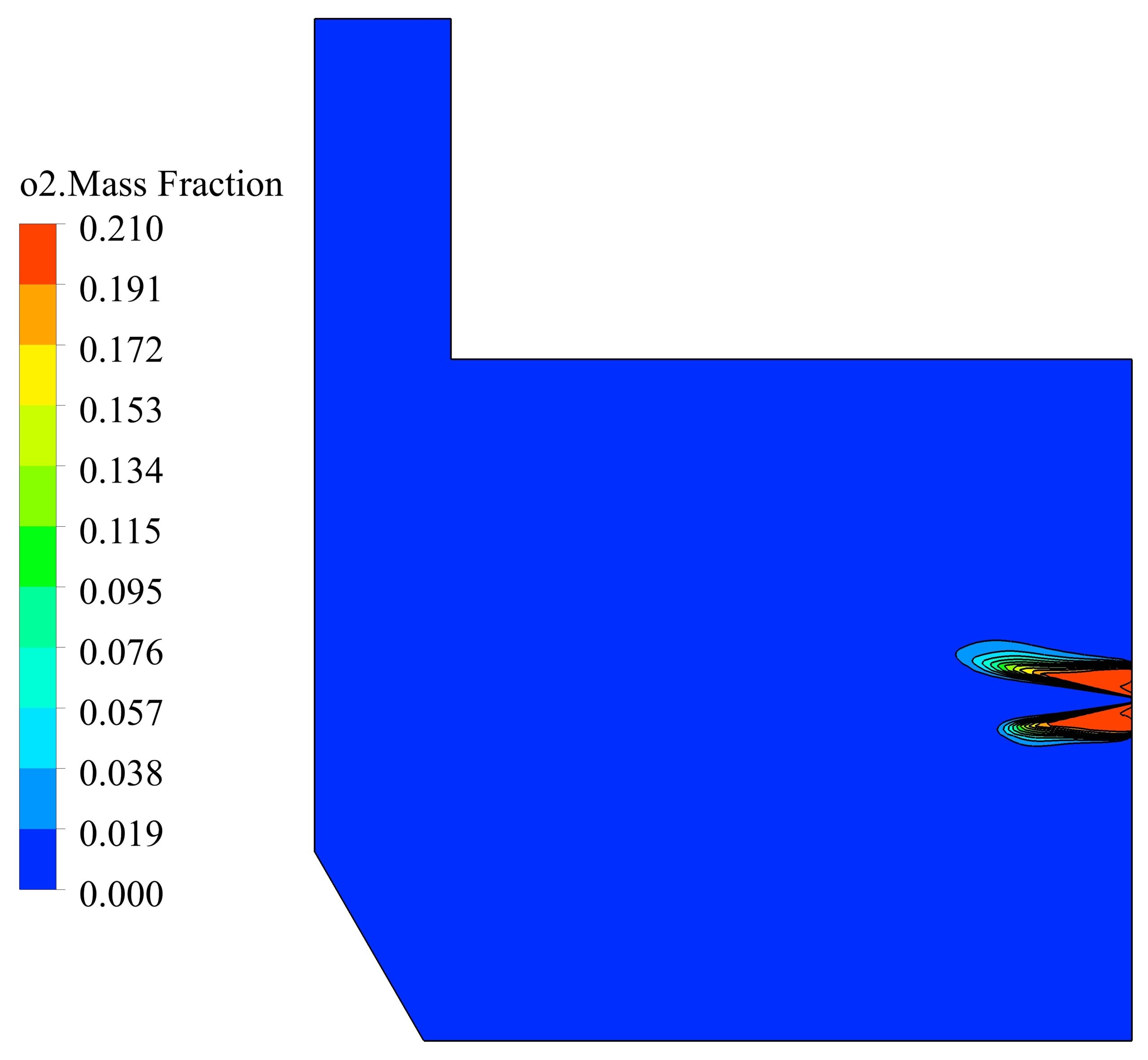
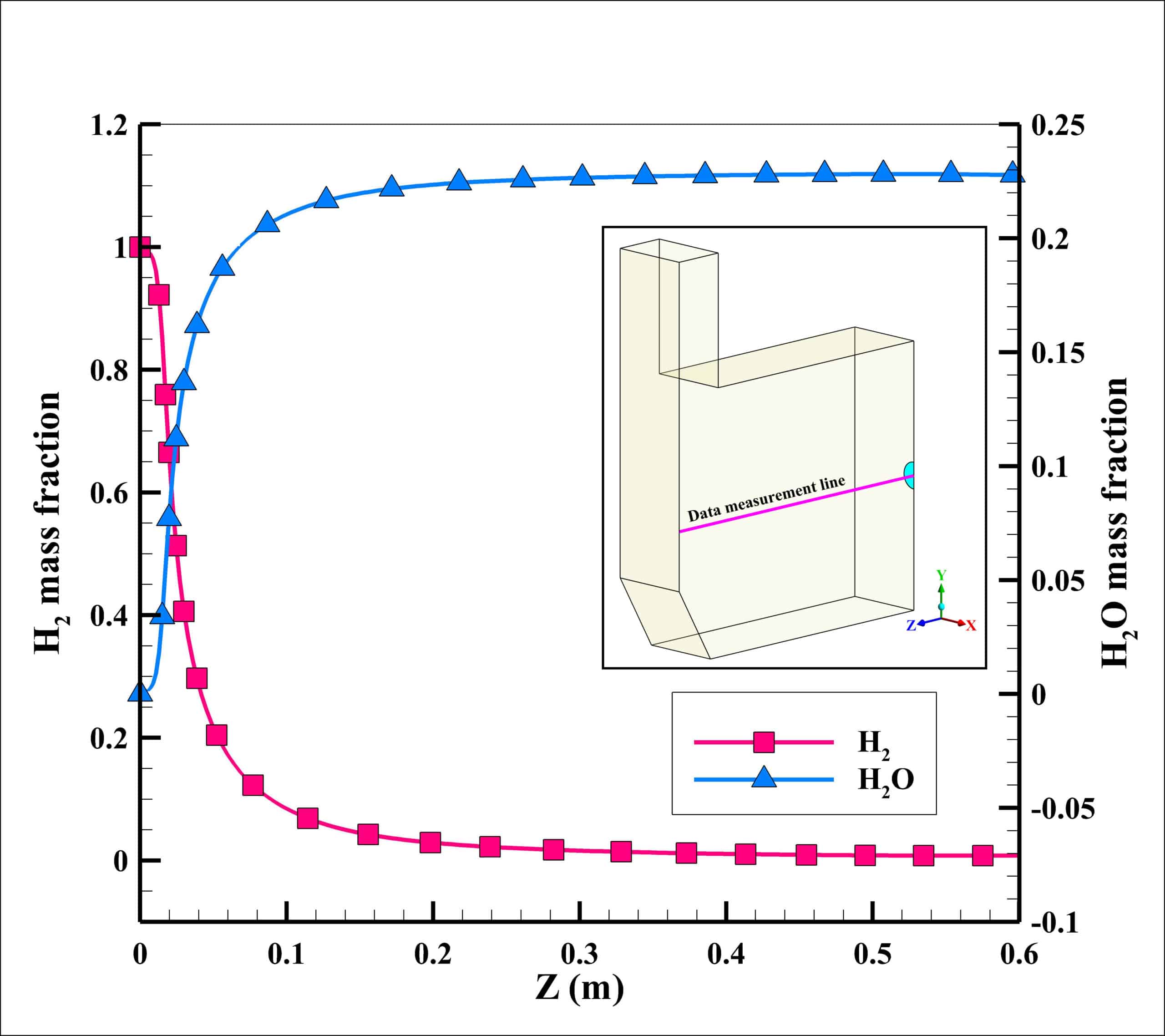
In this project, the combustion of stoichiometric non-premixed mixture of air/hydrogen is simulated in a furnace with dimensions of 0.6×0.3×0.5 m. The mass flow rate and temperature of the air at the inlet are considered to be 0.01 Kg/s and 300 K, respectively. The fuel temperature at the inlet is considered to be the same as the air temperature. The results with high accuracy indicate the precise settings of the software and the convergence of the solution. With using the eddy dissipation method, the relationship between the energy cascade and the high temperature domain of the furnace is clearly shown in the results. However, the reaction rate, mass fraction of the reactants component, temperature and velocity show the high accuracy of the simulation.




Reviews
There are no reviews yet.