Orifice for Methane Gas Flow, CFD Simulation by ANSYS Fluent Training
Free
- The problem numerically simulates the Orifice for Methane Gas Flow using ANSYS Fluent software.
- We design the 3-D model by the Design Modeler software.
- We mesh the model with ANSYS Meshing software.
- The mesh type is Structured, and the element number equals 54648.
To Order Your Project or benefit from a CFD consultation, contact our experts via email (info@mr-cfd.com), online support tab, or WhatsApp at +44 7443 197273.
There are some Free Products to check our service quality.
If you want the training video in another language instead of English, ask it via info@mr-cfd.com after you buy the product.
Description
Description
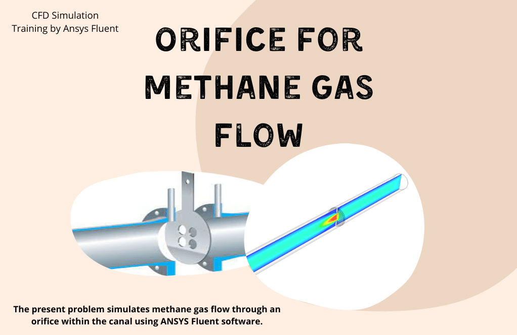
The problem simulates methane gas flow through an Orifice within the canal using ANSYS Fluent software. We perform this CFD project and investigate it by CFD analysis.
The simplest orifice model consists of a perforated plate perpendicular to the desired channel’s fluid flow path. The present model is designed in three dimensions using Design Modeler software.
The model is a channel 12 inches long and 0.5 inches in diameter, in the middle of which a cross-sectional reduction means with a diameter of 0.25 inches exists.
The meshing of the present model has been done using ANSYS Meshing software. The mesh type is Structured, and the element number equals 54648.
Orifice Methodology
The orifice is one of the most common devices for measuring mass flow using pressure difference transmitters.
The orifices’ operating mechanism is such that when the fluid passes through an orifice, its velocity increases due to the reduction of the cross-sectional area of the flow and according to the law of mass conservation and flow constant and according to the Bernoulli principle.
Similarly, when the fluid exits the orifice, the flow velocity decreases again due to the increase in the cross-sectional area of the flow. As a result, the flow pressure increases.
Therefore, a certain amount of pressure difference appears on both sides of the orifice, measured using pressure transmitters and built-in pressure sensors.
As a result, the orifice flow meter uses the same amount of pressure difference to calculate the flow rate of the fluid passing through the desired channel (taking into account the amount of pressure drop and the ratio of the diameter of the orifice hole to the channel diameter).
The fluid studied in this simulation is methane gas, with a density of 0.6679 kg/m3 and a viscosity of 0.00001087 kg/m.s. This flow enters the channel at a velocity equal to 0.033 m/s and exits at a pressure equal to atmospheric pressure.
Also, the RNG k-epsilon model is used to solve turbulent fluid equations.
Orifice Conclusion
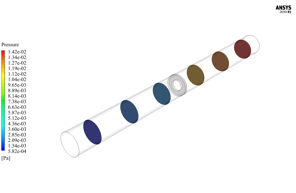
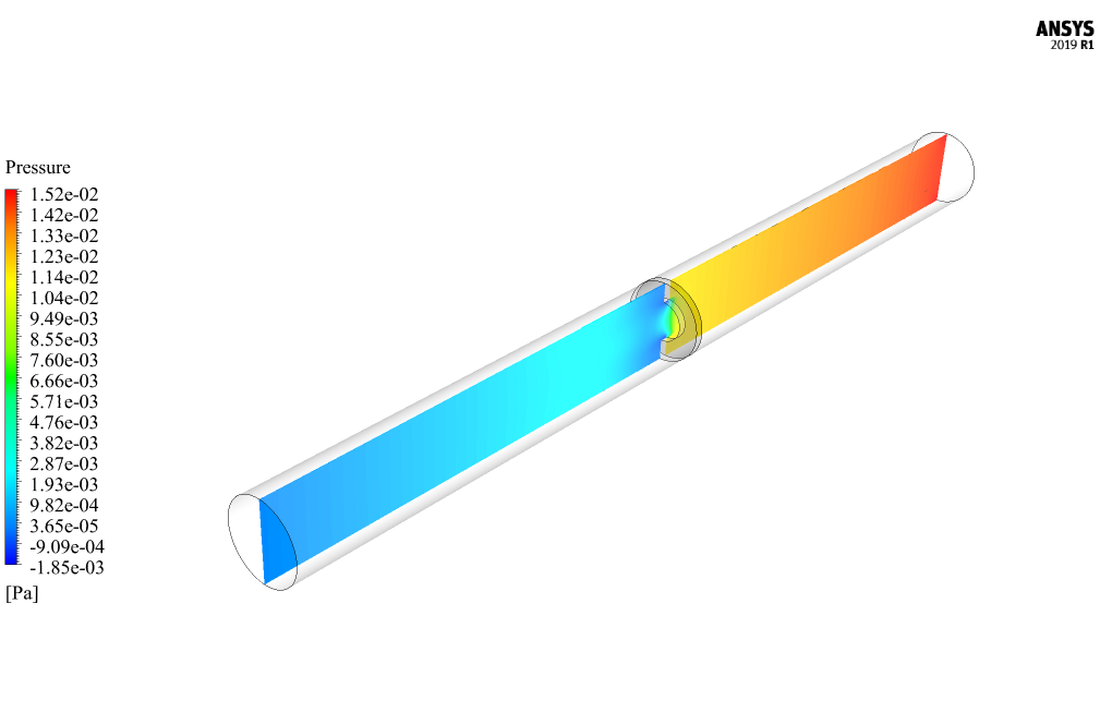
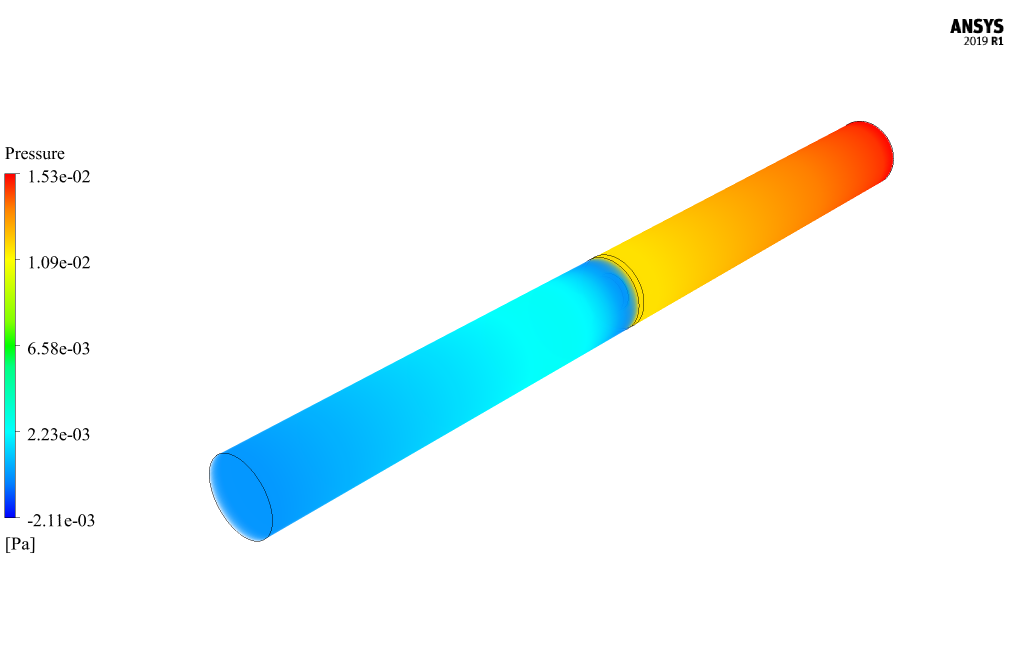
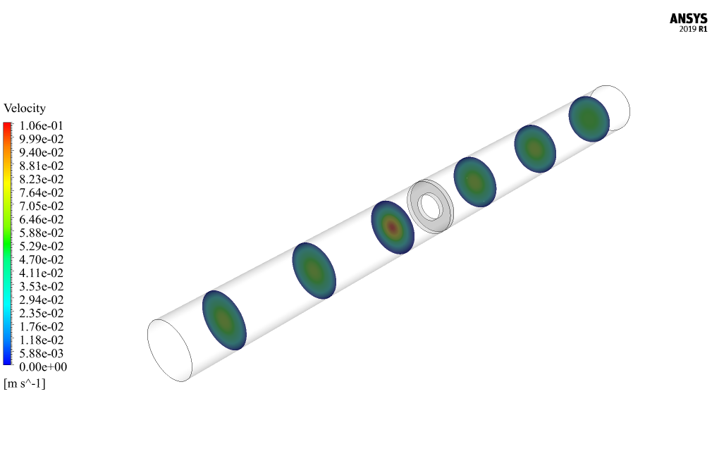
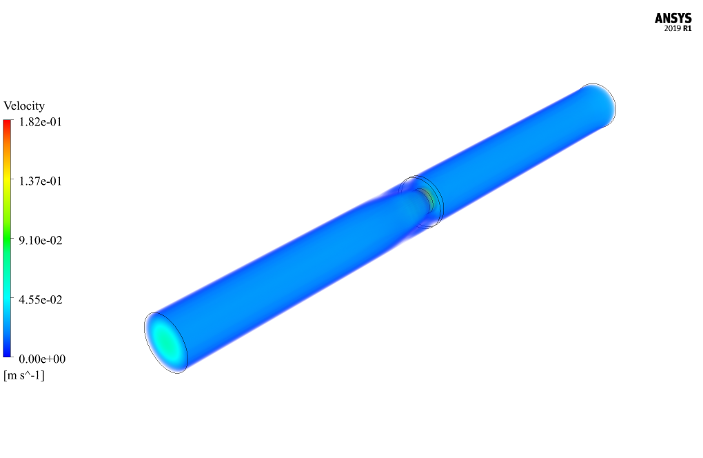
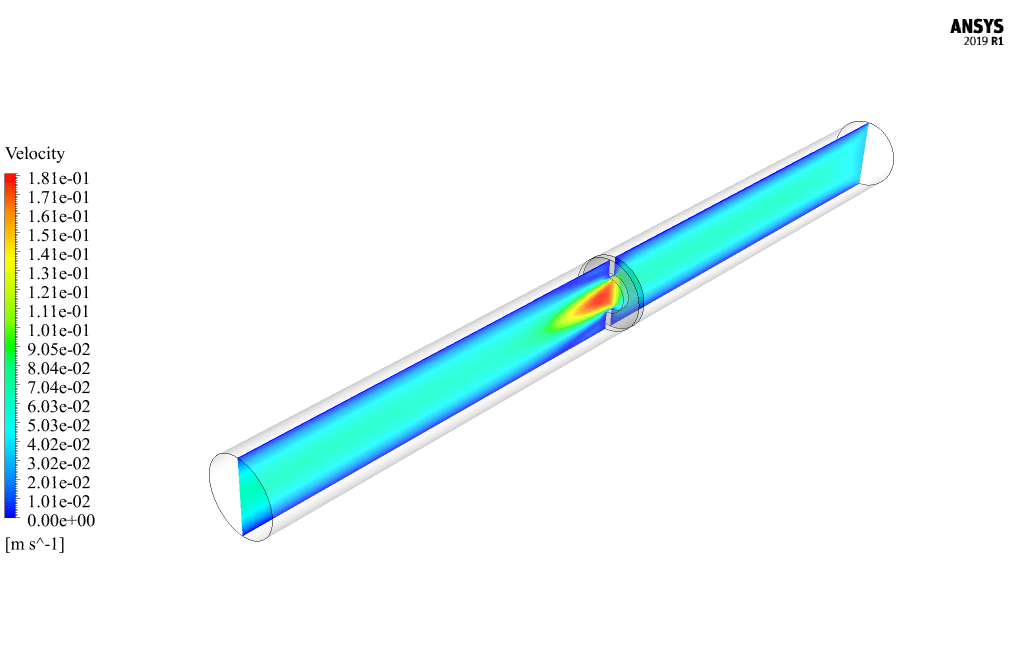
At the end of the solution process, two-dimensional and three-dimensional contours related to velocity and pressure are obtained. Also, the diagram of pressure and velocity changes in the direction of the channel’s central axis and crossing the section related to the orifice has been obtained.
As can be seen from the diagrams and contours, the flow velocity suddenly increases and decreases when the fluid flows through the orifice due to a sudden change in cross-sectional area. The pressure drop in the fluid flow in the path passing through the orifice section can also be seen.


Jamey Prohaska –
The innovative use of CFD in this simulation is commendable!
Lukas Dibbert –
How does the simulation model the behavior of the methane gas?
MR CFD Support –
The simulation uses the principles of fluid dynamics to model the behavior of the methane gas. It takes into account factors such as pressure, temperature, and velocity, providing a detailed picture of the gas flow.
Clay Wehner –
What kind of data can I get from this simulation?
MR CFD Support –
The simulation can provide a wealth of data, including pressure distribution, velocity profiles, and temperature distribution. This data can help you understand the performance of the orifice and optimize its design.
Prof. Jude Howe DVM –
This detailed simulation of the methane gas flow through an orifice is fantastic. Impressive work on charting pressure and velocity changes, effectively showcasing the phenomena associated with orifices.
MR CFD Support –
Thank you for your positive feedback. We are delighted to hear that the simulation met your expectations and provided you with insightful information on the behavior of methane gas flowing through an orifice. If you have any further questions or need assistance with your projects, feel free to reach out to us!
Elbert Johnston –
The project sounds fascinating. I am curious if temperature changes or thermal effects are taken into consideration for this orifice simulation with methane gas flow?
MR CFD Support –
In the presented simulation, the primary focus is on the methane gas flow dynamics and the pressure drop across the orifice. The thermal effects and temperature changes are not explicitly stated in the description. If temperature effects are essential for your application, this might require a different setup which takes energy equations into account.
Dillon Gutmann –
I’m amazed by the detailed simulations of methane gas flow you accomplish with ANSYS Fluent. Curious about the accuracy, how well does the simulated pressure drop across the orifice match experimental or theoretical values?
MR CFD Support –
In our CFD simulations, such as the one for methane gas flow through an orifice, we carefully calibrate our models to ensure a high degree of accuracy. This includes matching the simulated pressure drop across the orifice with experimental data whenever available or using established theoretical models. The degree of accuracy is influenced by the precision of the input parameters, quality of the mesh, and the appropriateness of the turbulence model and numerical methods applied.
Sarah Baumbach –
I’ve learned a lot about CFD using your training module on the Orifice for Methane Gas Flow! It was straightforward, and the results were clear. The correlation between the theory and the simulation results helped strengthen my understanding of the orifice’s function in measuring methane flow.
MR CFD Support –
Thank you for your positive feedback on the Orifice for Methane Gas Flow CFD Simulation training. We’re delighted to hear that the module was helpful and the theory-to-results correlation was clear, strengthening your understanding. Your satisfaction with our training content is highly appreciated, and we look forward to providing you with more valuable learning experiences.
Juliet Bayer –
I’m impressed with the detailed analysis of the methane gas flow through an orifice in your CFD simulation! It seems that the principles of flow conservation and Bernoulli’s fluid dynamics are effectively applied to model the pressure and velocity changes. The ability to visualize pressure and velocity at different sections is very valuable for understanding the characteristics of the flow. Great job on implementing the RNG k-epsilon model for turbulence. This training must provide solid understandings in flow measurement and pressure difference application.
MR CFD Support –
Thank you for recognizing the intricacies of our CFD simulation on methane gas flow through an orifice and the principles that guide our analyses. We ensure that our training materials provide a comprehensive insight into fluid dynamics, and we’re glad to hear that our efforts in visualizing flow characteristics are adding value. Your feedback strengthens our passion for delivering high-quality education in CFD analysis. If you have any further questions or require deeper understanding in specific aspects, don’t hesitate to reach out.
Ms. Marcelle Wunsch PhD –
Can the simulation handle different types of gases?
MR CFD Support –
Absolutely! The simulation can be adapted to handle different types of gases by changing the gas properties in the simulation setup. This makes it a versatile tool for various applications.
Lorena Schuster –
Could you explain what kind of pressure transmitters or sensors were used in the simulation for measuring the pressure drop across the orifice?
MR CFD Support –
In this CFD simulation, the pressure drop across the orifice is a calculated parameter rather than being measured by physical transmitters or sensors. Within ANSYS Fluent, virtual sensors are defined by setting monitor points at relevant locations in the simulated domain, which allows for the tracking of pressure changes as the methane gas flows through the orifice and thereby simulating the role of pressure difference transmitters.