Packed Bed Reactor with Particles CFD Simulation
$100.00 $50.00 Student Discount
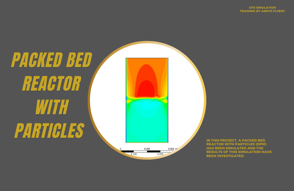
In this project, a Packed Bed Reactor with Particles has been simulated, and the results of this simulation have been investigated.
Click on Add To Cart and obtain the Geometry file, Mesh file, and a Comprehensive ANSYS Fluent Training Video.To Order Your Project or benefit from a CFD consultation, contact our experts via email (info@mr-cfd.com), online support tab, or WhatsApp at +44 7443 197273.
There are some Free Products to check our service quality.
If you want the training video in another language instead of English, ask it via info@mr-cfd.com after you buy the product.
Description
Packed Bed Reactor with Particles, CFD Simulation Training with Ansys Fluent
Reactor models vary from pseudo-homogeneous to heterogeneous, from one-dimensional to three-dimensional, and from assumed flow patterns to computed flow and transport fields.
Packed bed reactors, also known as fixed-bed reactors, are often used for catalytic processes. A packed bed reactor (PBR) is preferred for heterogeneous reactions, where the solid-fluid contact dramatically influences the reaction rate. A PBR is a cylindrical vessel filled with solids (a reactant). The other reactant is allowed to enter the bed through the inlet face.
For the fluidized bed membrane reactor, it is well known that a virtually isothermal condition can be achieved. In contrast, for the packed bed membrane reactor, a temperature drop in the first part of the reactor is always observed irrespective of the temperature profile at the reactor wall.
A fluidized bed typically allows for a more uniform product than other reactor designs. There are a few disadvantages to using fluidized beds. Unlike fluidized beds, pack beds have poor mixing and are heterogeneous.
Geometry & Mesh
The geometry of the solution is a 2d rectangle in the XY plane. The rectangle length is 120 mm, and the width is 40 mm. The geometry is designed in design modeler software:
Ansys meshing software is used to generate meshes of the solution. The elements are all in quad shape (Structure), and the number of them is equal to 5000:
Packed bed Reactor with Particles CFD Simulation
We consider several assumptions to simulate the present model:
- We perform a pressure-based solver.
- Simulation has only examined fluid behavior; in other words, heat transfer simulation has not been performed.
- The present model is unsteady.
- The effect of gravity is -9.81 m.s-2 along the y-axis in the present model.
The following table represents a summary of the defining steps of the problem and its solution:
| Models | ||||
| k-omega | Viscous model | |||
| SST | k-epsilon model | |||
| mixture | turbulence multiphase model | |||
| eulerian | Multiphase model | |||
| implicit | formulation | |||
| gas and particles | phases | |||
| implicit | formulation | |||
| Boundary conditions (Packed Bed) | ||||
| velocity-inlet | Inlet | |||
| 0 pascal | supersonic/initial gauge pressure | mixture | ||
| 0.05 m.s-1 | velocity magnitude | flow | ||
| 1 | volume fraction | |||
| 0 m.s-1 | velocity magnitude | particles | ||
| 0 | volume fraction | |||
| Pressure outlet | Outlet | |||
| 0 pascal | gauge pressure | mixture | ||
| wall | upper and bottom wall | |||
| stationary wall | wall motion | |||
| Solution Methods (Packed Bed) | ||||
| Phase Coupled SIMPLE | Pressure-velocity coupling | |||
| PRESTO | pressure | Spatial discretization | ||
| first-order upwind | momentum | |||
| first-order upwind | turbulent dissipation rate | |||
| first-order upwind | turbulent kinetic energy | |||
| first-order upwind | volume fraction | |||
| Initialization (Packed Bed) | ||||
| Standard, patch | Initialization method | |||
| 0 m.s-1 | flow velocity (x) | |||
| 0 m.s-1 | flow velocity (y) | |||
| 0 pascal | gauge pressure | |||
| 0 m.s-1 | particle velocity (x,y) | |||
| 0 | particle volume fraction | |||
| 0.65 | particle volume fraction | patch | ||
Results & Discussion
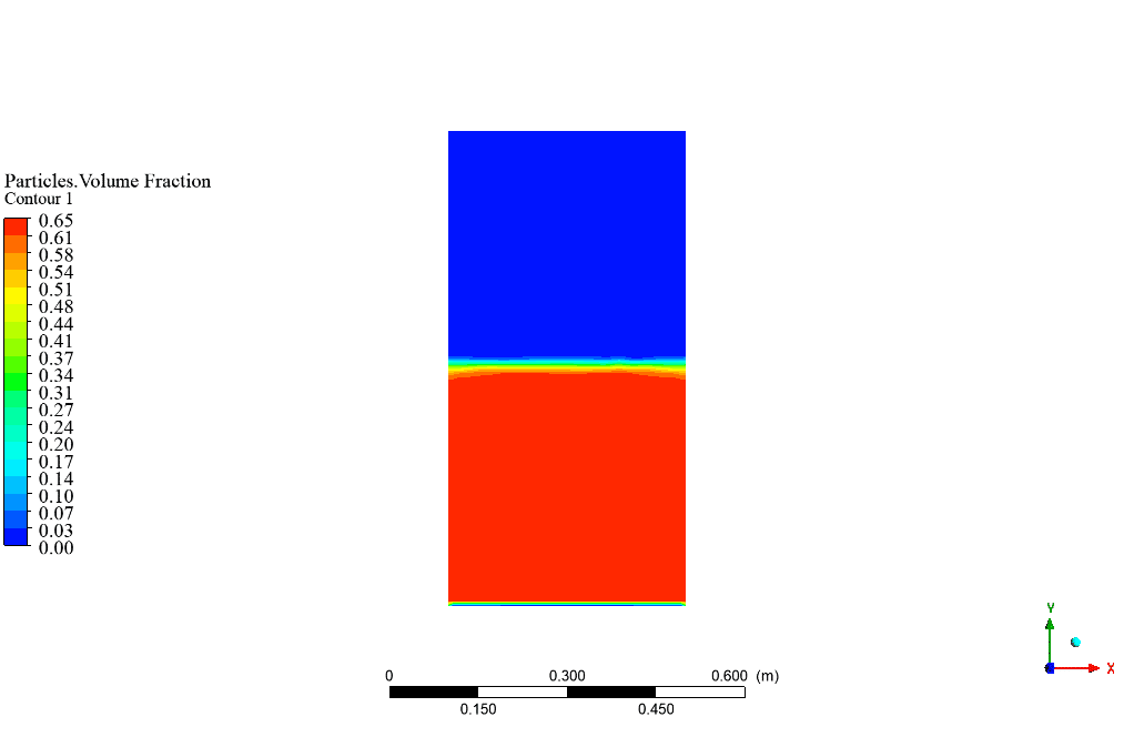
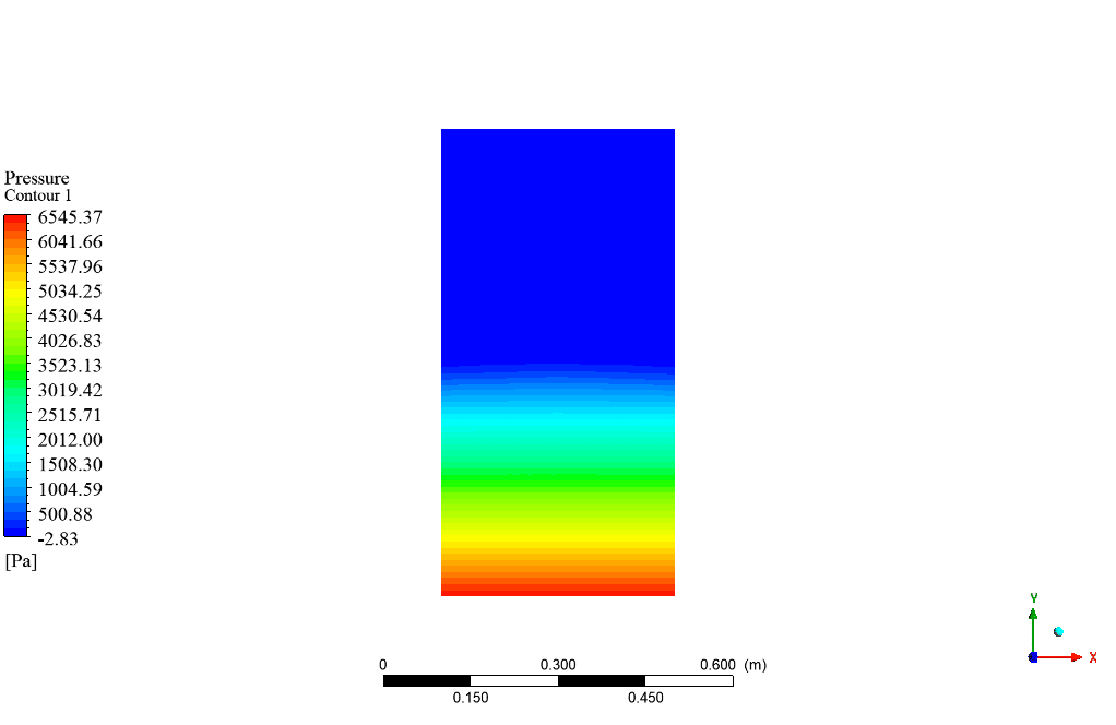
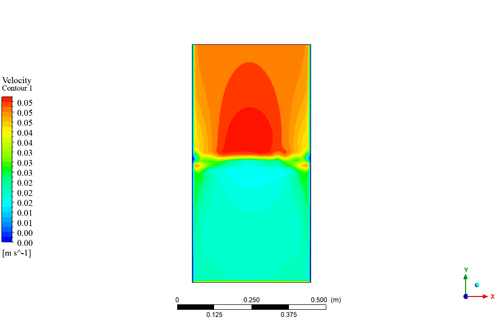
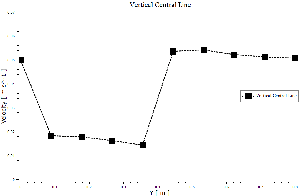
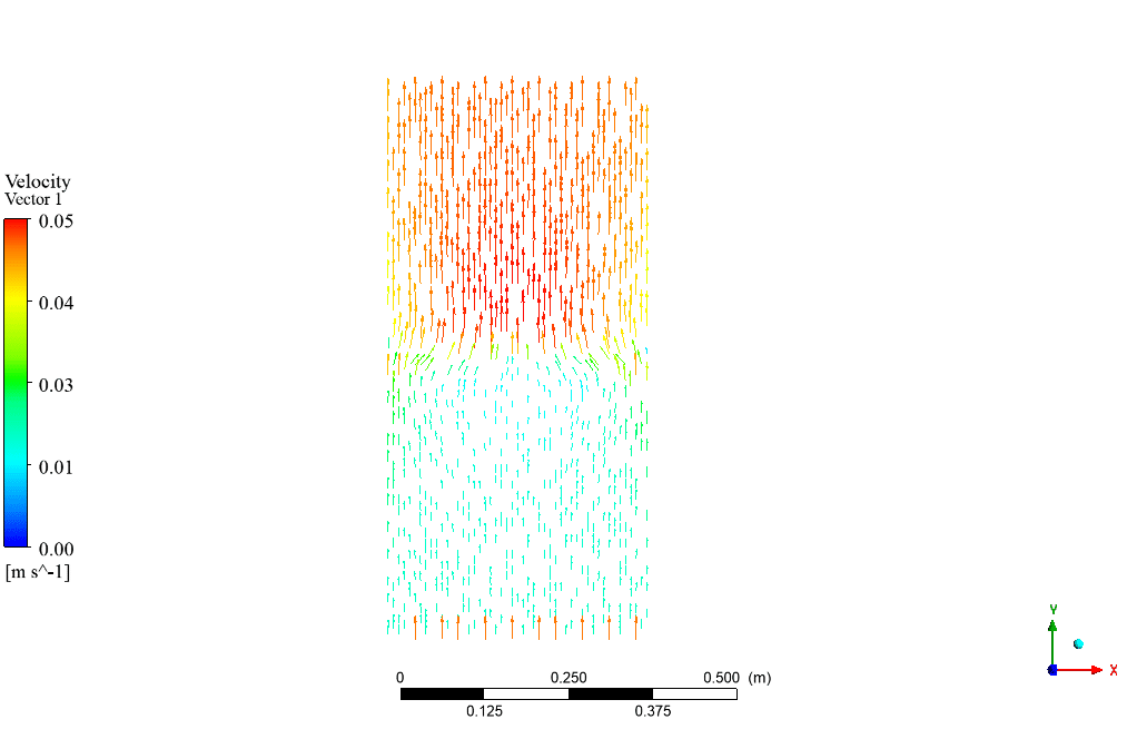
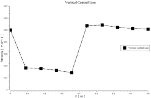
At the end of the solution process, two-dimensional contours related to pressure and velocity and volume fraction of water and alumina particles are obtained. At first, water flow enters the reactor, passes through the particles (Particles are packed and fixed at the lower half of the reactor), and finally moves to the outlet face at the same speed as inlet velocity. Also, static pressure contour is obtained in the whole domain, and as it can be seen, it decreases while passing through the particles, and after that, till reaching the outlet face, it’s constant and equal to zero.



Reviews
There are no reviews yet.