Partially Premixed Combustion, Non-Adiabatic, Chemical Equilibrium, ANSYS Fluent CFD Training
$140.00 $70.00 Student Discount
- The problem numerically simulates the non-adiabatic combustion in a combustion chamber using ANSYS Fluent software.
- We design the 2-D model with the Design Modeler software.
- We mesh the model with ANSYS Meshing software.
- The mesh type is Structured, and the element number equals 4700.
- We use Partially Premixed Combustion to define combustion reaction.
- We use the Chemical Equilibrium and Non-Adiabatic modes for energy treatment.
To Order Your Project or benefit from a CFD consultation, contact our experts via email (info@mr-cfd.com), online support tab, or WhatsApp at +44 7443 197273.
There are some Free Products to check our service quality.
If you want the training video in another language instead of English, ask it via info@mr-cfd.com after you buy the product.
Description
Description
The present problem simulates the Non-Adiabatic combustion in a combustion chamber by ANSYS Fluent software. In the present case, it is assumed that there are two different inlet boundaries, one for pure air and the other for a mixture of fuel and air.
These two flows mix inside the combustion chamber and are considered Partially premixed.
The geometry of the present model is two-dimensional and has been designed using Design Modeler software. We do the meshing of the present model with ANSYS Meshing software. The mesh type is Structured, and the element number is 4700.
This CFD project is the 8th episode of the Combustion Training Course.
Partially Premixed Combustion Methodology
The Partially Premixed Combustion model is used to model the combustion process. Non-Adiabatic energy treatment and a Chemical Equilibrium model are used to model the combustion process.
A PDF Table is generated to store data related to temperature changes, mixture density, and different chemical species mass fractions before simulation to be used during the main calculations.
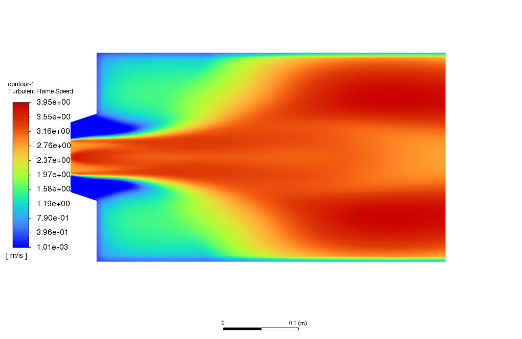
Also, the Zimont model has been used for the Turbulent Flame Speed Model. Firstly, the cold flow combustion simulation is performed to obtain an initial solution regarding the flow patterns by disabling equations related to combustion.
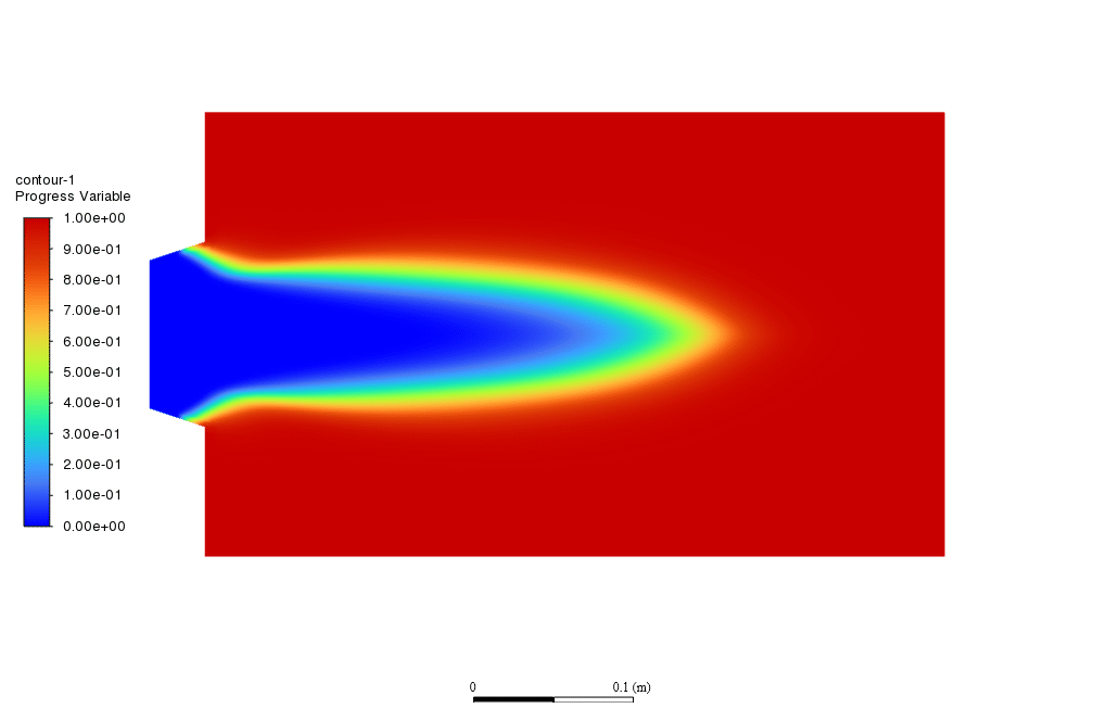
In the second stage, the patch option is used to attach a constant value of the progress variable to the domain. Simultaneously, the combustion-related equations are enabled to reach the final solution.
Also, the Energy Equation is On to calculate the changes in temperature due to the combustion process, and the Viscous is set as the Standard k-epsilon model.
Partially Premixed Combustion Conclusion
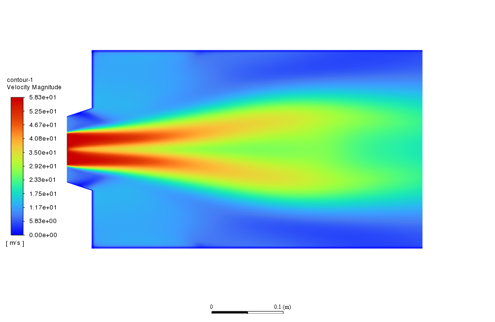
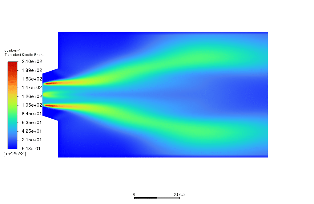
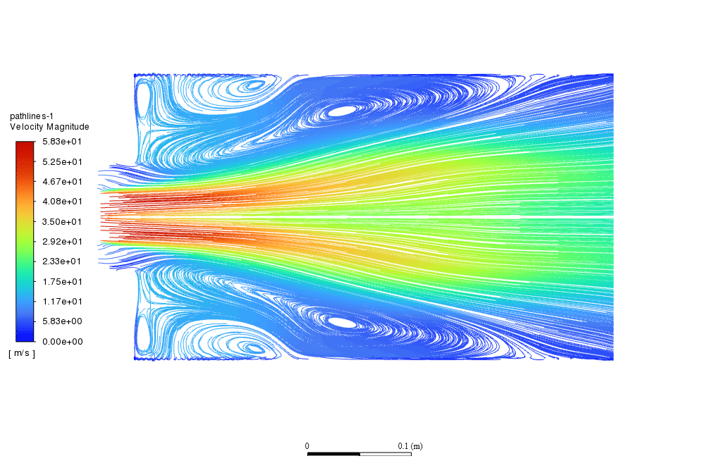
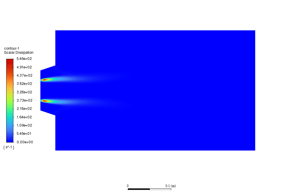
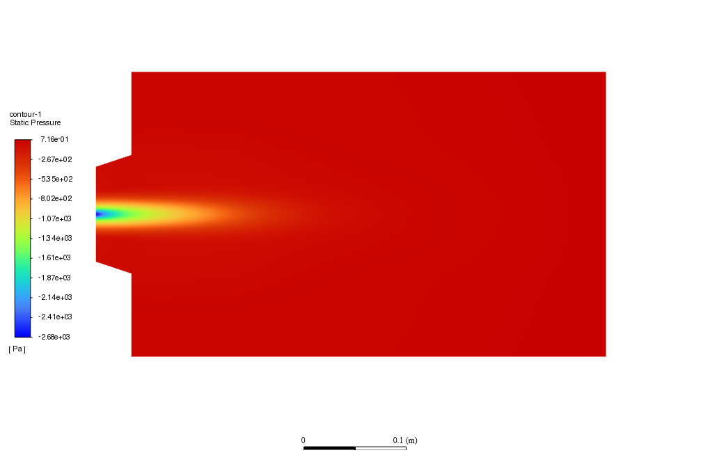
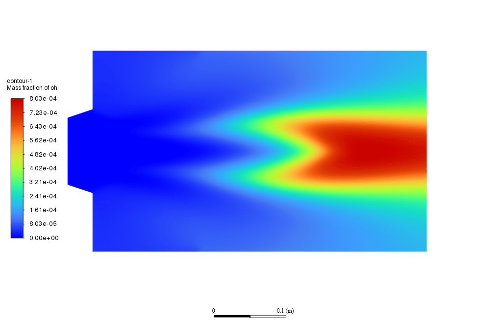
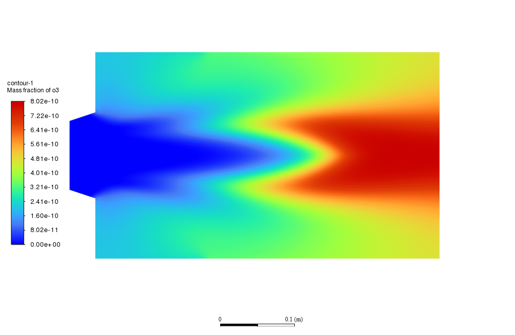
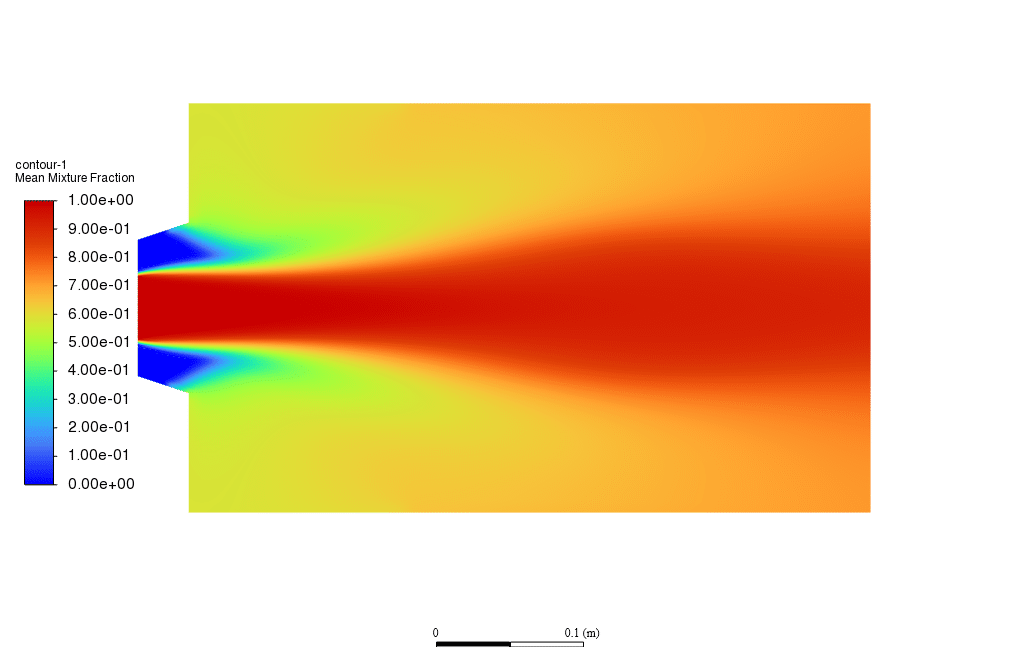
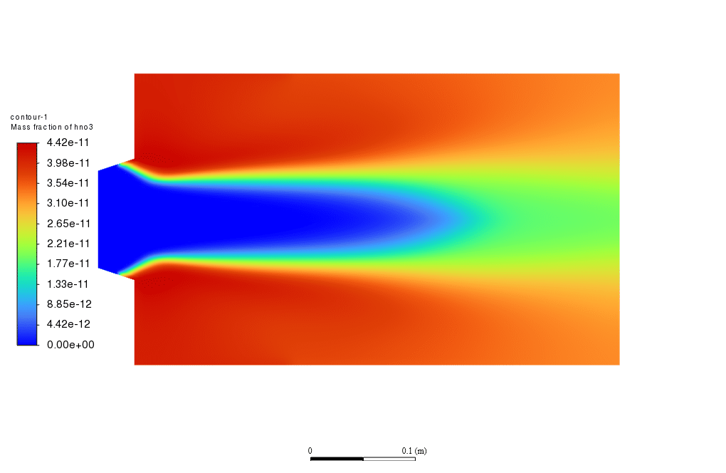
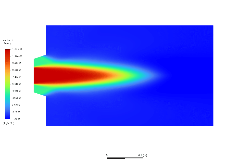
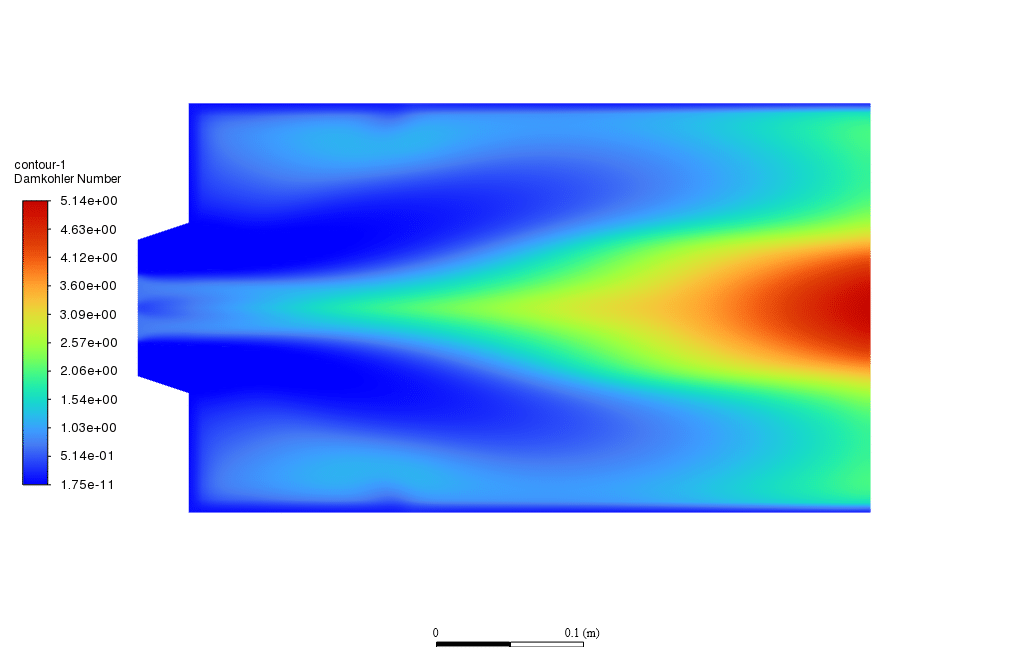
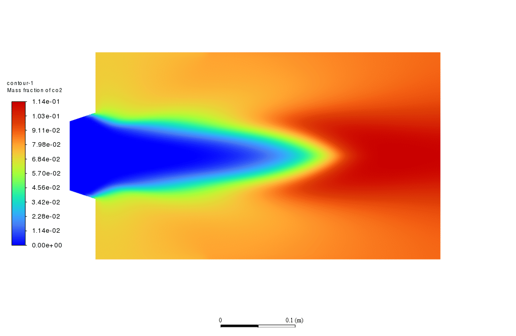
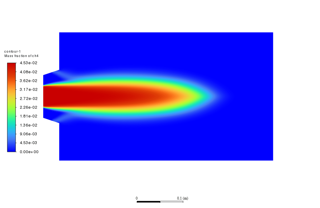
After the simulation process was finished, contours such as temperature, velocity, different species’ mass fractions, and streamlines were obtained. As shown in the temperature contour, the temperature has increased in the chamber, indicating that the combustion has taken place.
Also, the formed secondary flows in the chamber are shown in the streamlines. These secondary flows have the role of increasing the mixing process between fuel and air and hence enhancing the combustion process.




Reviews
There are no reviews yet.