Perforated Plate (Porous Zone) Inside 3D Channel CFD Simulation
$60.00 $30.00 Student Discount
- The problem numerically simulates a perforated plate (Porous Zone) inside 3D Channel using ANSYS Fluent software.
- We modeled the geometry using ANSYS Design Modeler and created the mesh using ANSYS Meshing software.
- The mesh type is Structured and the number of them is 14,544.
- Porosity has been used in the simulation.
- Pressure Drop inside the channel due to porosity is investigated.
To Order Your Project or benefit from a CFD consultation, contact our experts via email (info@mr-cfd.com), online support tab, or WhatsApp at +44 7443 197273.
There are some Free Products to check our service quality.
If you want the training video in another language instead of English, ask it via info@mr-cfd.com after you buy the product.
Description
Perforated Plate (Porous Zone) Inside 3D Channel CFD Simulation, ANSYS Fluent Tutorial
Description
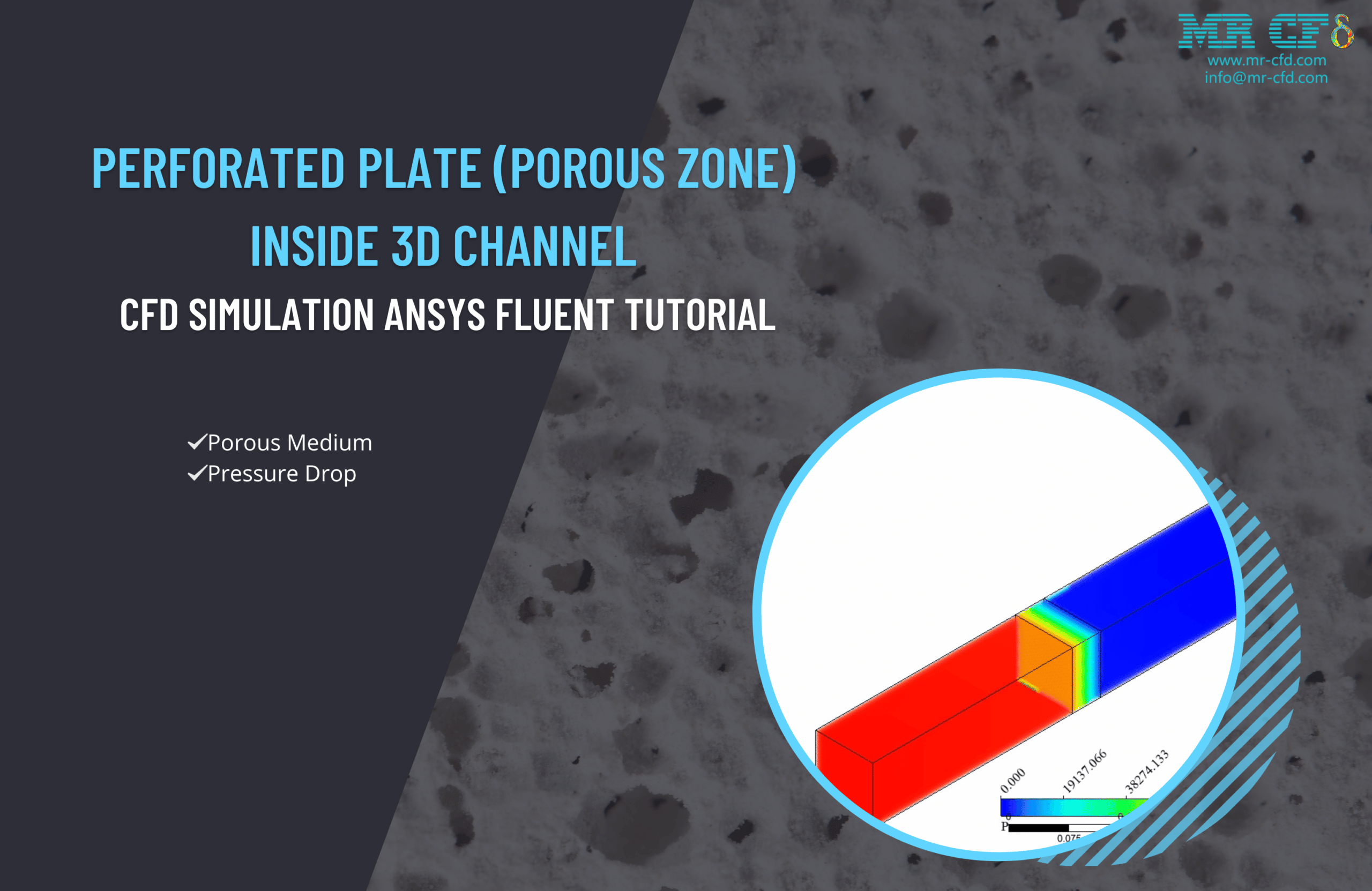
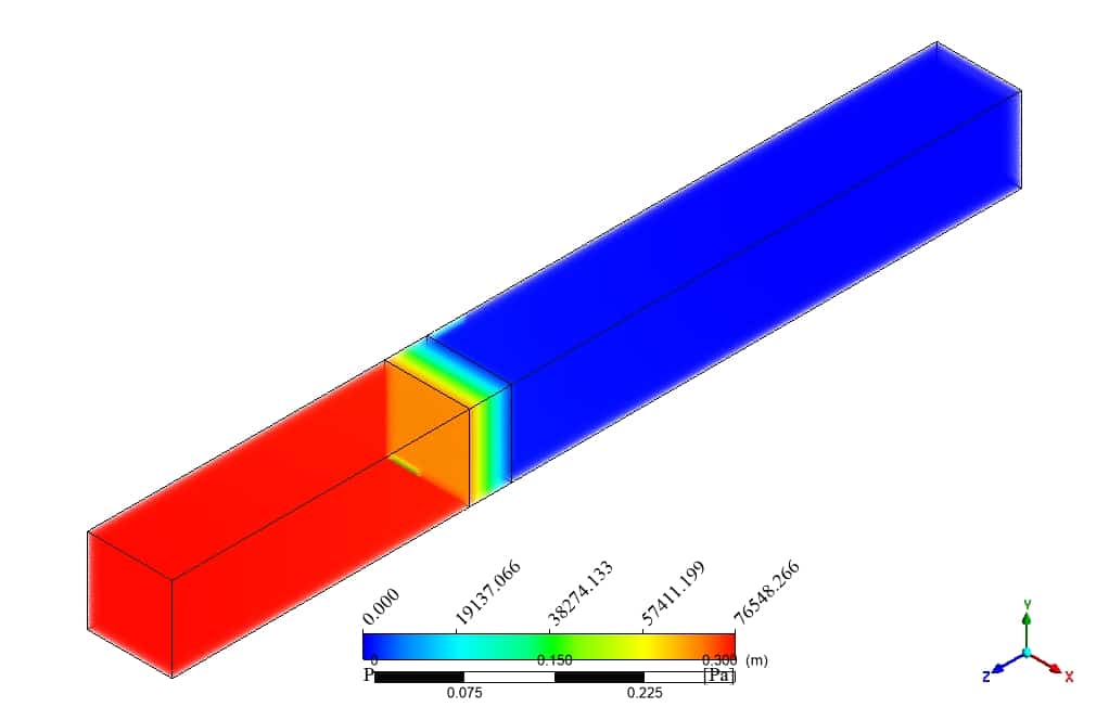
In this project, a channel equipped with a Perforated Plate is simulated in 3-dimensional. Water enters the domain from the inlet with a 5m/s velocity magnitude and collides with the porous zone. This interaction results in a sudden pressure drop.
The 3D geometry was modeled in Design modeler software. A channel with a 1-meter length in the z-direction and a perforated plate is located 40 cm away from the inlet. In addition, a Structured mesh grid was carried out using ANSYS Meshing software, and overall, 14,544 elements were generated.
This CFD project is the 7th episode of the ANSYS Fluent General Training Course.
Methodology: perforated plate (Porous Zone) inside 3D Channel
The pressure-based solver is employed due to the incompressibility of the water. The gravitational acceleration is applied in the negative direction of the Y-axis.
Also, the porous model is used inside the channel.
Conclusion
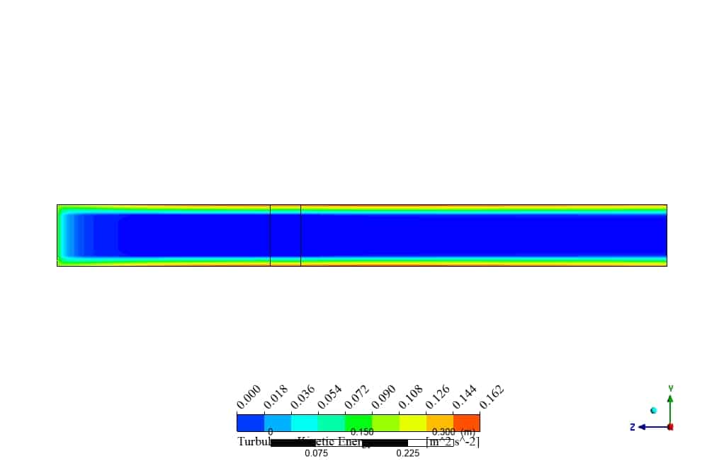
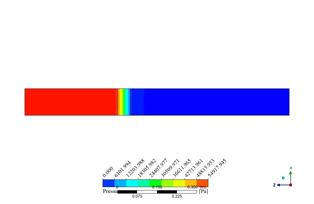
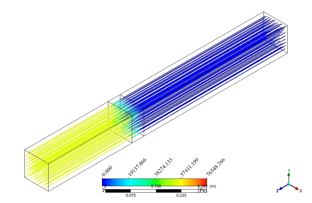
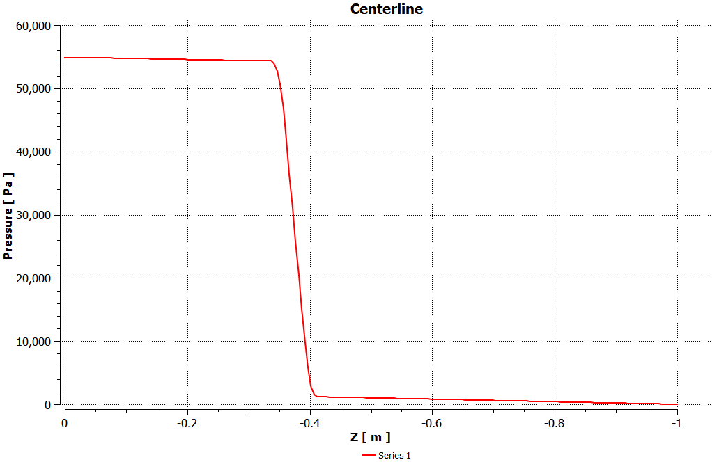
The water flow enters the channel with a 5m/s velocity magnitude. After a while, a collision with a perforated plate with 0.25 porosity causes an extreme pressure drop. As can be seen in the following plot, the amount of pressure drop decreases suddenly from 55,000 to almost zero. Also, this pressure drop is clearly visible in the 2D and 3D contours above.
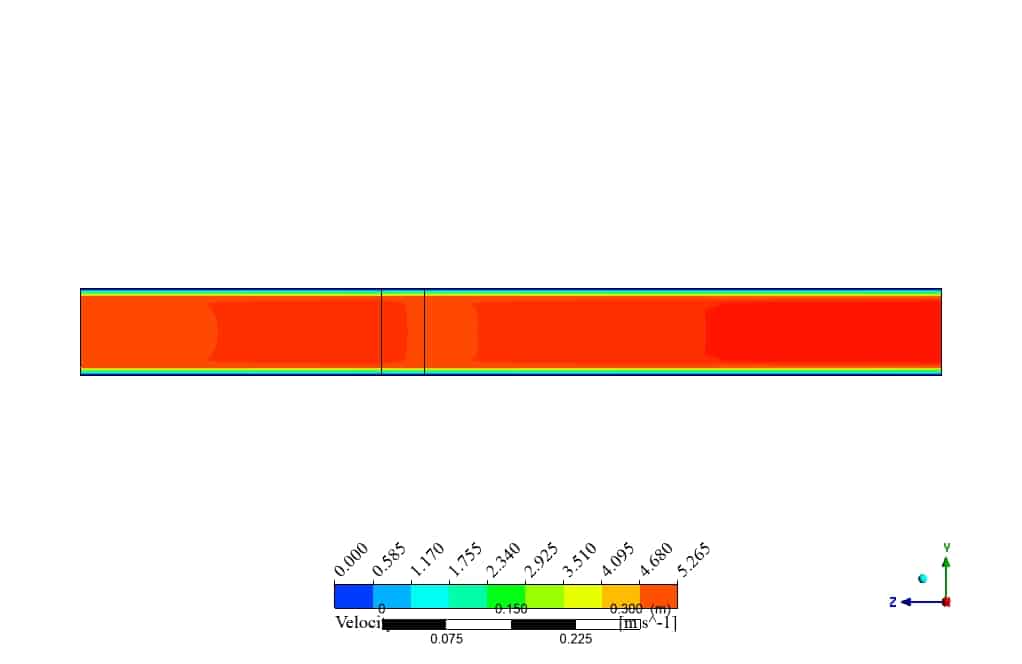
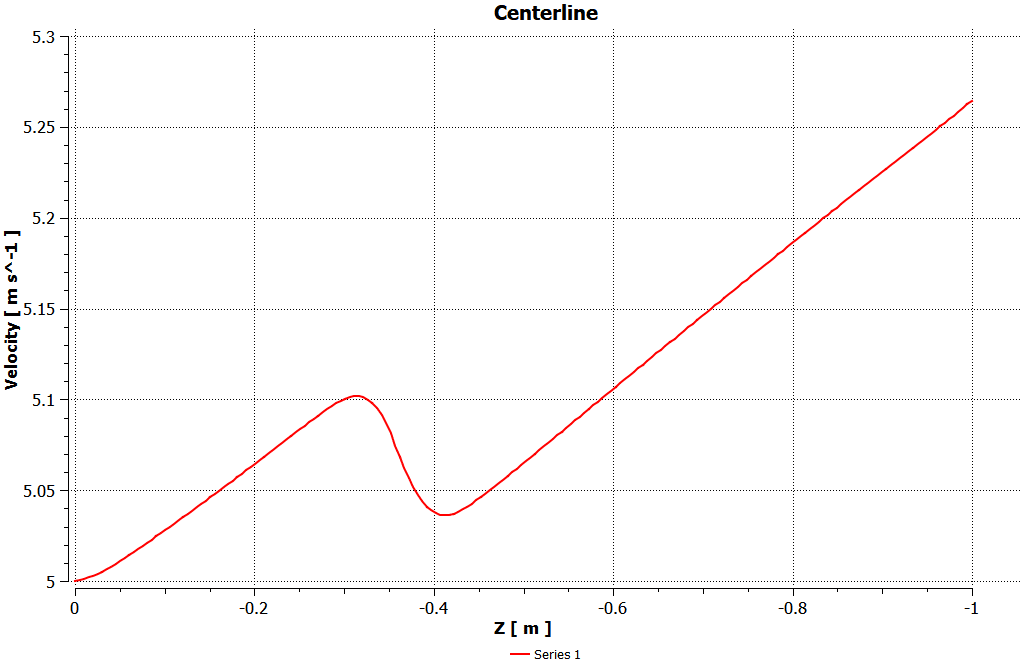
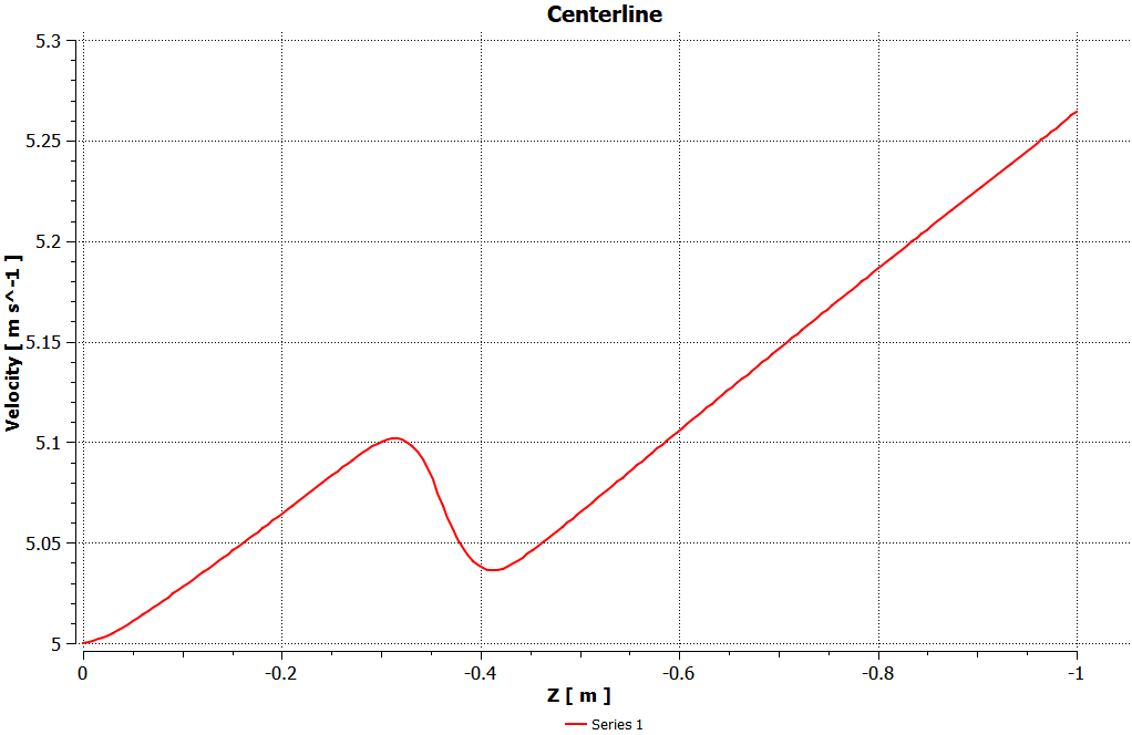
Concerning the velocity magnitude of water inside the channel, it starts to increase from the entrance until it reaches the porous zone. Due to the interactions inside the porosity, the velocity decreases and after that starts to increase with the same slope it had at the beginning.


Garry Kessler –
I’m pleased to see such a detailed explanation in the product description. It sounds like a comprehensive study. I’m curious about something though; how exactly does the porosity of the perforated plate impact the flow and how is this represented in the simulation?
MR CFD Support –
The porosity of the perforated plate represents the availability of open space through which the fluid can flow. In the simulation, a porous media model is employed to account for the resistance to flow imposed by the perforated plate. This model effectively reduces the momentum of the flow in proportion to the defined porosity and the permeability parameters of the porous zone. The resulting interaction causes a pressure drop across the plate as the fluid must exert more force to pass through the smaller passages. The impact of porosity on the flow is visualized in the simulation through the changes in velocity and pressure contours. It’s an important parameter that influences turbulence and flow dynamics in the system.
Lily Cummings –
Fantastic tutorial! The clear explanation of the porous model usage and pressure drop visualization across the perforated plate was instrumental in understanding the complex fluid dynamics in a 3D channel. Watching the velocity change across the channel gave me a comprehensive insight into flow behavior.
MR CFD Support –
We appreciate your positive feedback! It’s wonderful to hear that our tutorial on 3D channel flow with a perforated plate in ANSYS Fluent was helpful for you to grasp the intricate details of fluid dynamics. Thank you for taking the time to share your experience.
Woodrow Lockman –
I found the simulation of the perforated plate fascinating! What exactly does the porous model do, and how is it implemented in this context?
MR CFD Support –
The porous model activates a special simulation feature that mimics the flow resistance caused by the presence of the perforated plate without having to model each individual hole. This simplification is based on the porosity of the material and permeability values, which are assigned to the zone where the perforated plate exists. In this CFD simulation, the porous zone is defined by setting its resistance values in different directions affecting fluid velocity and resulting in a pressure drop as the flow passes through it.
Jacynthe Schoen –
I was really impressed with how the perforated plate simulation showed the pressure drop. Can you tell me what kind of industries would typically benefit from this kind of analysis?
MR CFD Support –
Industries that involve fluid flow control and separation processes would greatly benefit from such analysis. Chemical and petrochemical industries, wastewater treatment plants, power generation, automotive companies for various cooling and filtration applications, and HVAC systems in building designs are some examples where understanding the impacts of a perforated plate in a flow can be critical for optimization and safety.
Brendan Gleason V –
The simulation talks about a plate with 0.25 porosity. Can you explain how the porosity affects the flow and the pressure drop?
MR CFD Support –
The porosity of the plate affects the flow by controlling how much fluid is permitted to pass through it. With a 0.25 porosity, 75% of the plate area is solid, which resists the flow of water, causing a pressure drop. The porous zone obstructs and slows down the flow, resulting in reduced velocity and higher pressure drop directly after the plate. As the water passes through or around the porous zone, the flow encounters resistance, leading to the observed flow pattern and pressure decreases highlighted as ‘extreme pressure drop’ in the provided simulation results.
Miss Olga Rowe I –
I’ve used this tutorial for my project and found it incredibly detailed. The step-by-step instructions were clear, and I could simulate the perforated plate within my channel confidently. Thanks for this valuable resource!
MR CFD Support –
We’re delighted to hear that the tutorial was helpful for your project and that the instructions were clear and easy to follow. Your feedback is greatly appreciated, and it motivates us to continue providing valuable resources. Thank you for choosing our product!
Prof. Bradley Auer –
I just completed this tutorial on the perforated plate within a 3D channel, and it was an amazing learning experience. The explanations were clear, and the application of the porous model gave me great insights into how to handle pressure drop in CFD simulations. I could observe the pressure drop and flow velocity changes distinctly through the contour plots provided. Really appreciated the structured methodology, which made complex concepts easier to understand.
MR CFD Support –
We’re thrilled to hear that our Perforated Plate CFD Simulation tutorial Could provide you with the clear guidance and valuable insights you were looking for! Understanding the nuances of pressure drops and velocity changes in such setups is key, and your ability to grasp these concepts is exactly what we aim for. Thank you for choosing our learning product, and we commend you on your success in mastering this simulation. We’re always here to support your journey in CFD. Keep up the great work!
Anibal Anderson –
What specific features in ANSYS Fluent were used to simulate the flow through the porous medium and how were they valuable in capturing the pressure drop across the perforated plate?
MR CFD Support –
In ANSYS Fluent, the Porous Media model was utilized to simulate the flow through the porous medium of the perforated plate. This model accounted for the resistance offered by the plate to the flow, which is essential for calculating the pressure drop accurately. Features in Fluent, such as defining the porosity and permeability of the zone, allow for detailed representation of pressure and velocity changes due to the interaction with the porous material.
Dr. Lina Tillman DVM –
I was amazed by how the simulation captured the pressure drop across the perforated plate. Can you share how the porous model settings were calibrated for this particular setup?
MR CFD Support –
Thank you for the compliment! Regarding the porous model settings, parameters like porosity, and the resistance coefficients, both linear and quadratic (inertial loss coefficients), must be appropriately defined. These values depend on the physical characteristics of the perforated plate, such as hole size, distribution, and the thickness of the plate. Calibration is usually done using experimental data or correlations from the literature to simulate the pressure drop accurately.
Mrs. Daphney West –
Really impressed with the perforated plate simulation details. The methodology outlined was thorough and the conclusion demonstrated the impact of porosity on fluid dynamics visibly well. Great job!
MR CFD Support –
Thank you for your positive feedback on the Perforated Plate (Porous Zone) Inside 3D Channel CFD Simulation tutorial. We’re thrilled to hear that you found the details and results of the simulation to be clear and impressive. Your satisfaction with our products is our primary goal!
Candace Bahringer –
The tutorial was amazing, especially how you explained the sudden pressure drop across the porous zone. Wondering if you could showcase the change of velocity as water moves through the perforated plate.
MR CFD Support –
Thank you for the positive feedback! We’re delighted to hear that you found the tutorial on the Perforated Plate inside a 3D Channel simulation helpful. The change in water velocity through the perforated plate is quite significant. After passing through the zone with a porosity of 0.25, water velocity is reduced due to the obstruction, which then increases again as the water exits the porous zone and flows down the rest of the channel. These variations are well illustrated in both the 2D and 3D contours of velocity provided within the simulation results.
Carlos Beer IV –
I followed the tutorial and learned a lot from the episode. I was particularly impressed by how the simulation demonstrated the impact of the porous medium on the pressure drop. Also, being able to visually see the change in velocity magnitude before and after the porous zone was enlightening!
MR CFD Support –
We’re thrilled to hear that our tutorial on Perforated Plate Inside 3D Channel was of great benefit to you! It’s fantastic that you found the visual demonstrations enlightening. Understanding how porous media affect fluid dynamics is an important concept, and we’re glad our simulation could clearly illustrate that for you. Thank you for your positive feedback, and we hope you’ll find our other tutorials just as helpful!
Misty Waelchi –
I really enjoyed following through with this Ansys Fluent tutorial on simulating a perforated plate inside a 3D channel. It provided clear insights into how porosity can affect flow dynamics and pressure, particularly the way the pressure drops were visualized made the concept so much more tangible. Well done!
MR CFD Support –
Thank you for your positive feedback! We’re thrilled to hear that our Ansys Fluent tutorial was insightful and helpful in understanding the dynamics of flow through perforated plates. Your comprehension of the pressure drop and its visualization makes us proud of the tutorials we provide. If you need further assistance or information about similar simulations, we’re always here to help. Keep learning and exploring, and don’t hesitate to reach out to us with any questions!
Aimee Runte –
After the initial steep pressure drop across the perforated plate, does the velocity of the water remain steady as it moves towards the channel outlet or are there any further significant changes? I’d like to understand the flow dynamics better.
MR CFD Support –
After the water passes through the perforated plate, the flow dynamically adjusts to the reduced pore space, which initially leads to a reduction in velocity. Due to the conservation of mass in the incompressible flow, the velocity then increases downstream to compensate for the reduced cross-sectional area available for the flow after the pressure drop. As the water moves towards the outlet, it stabilizes to a steady-state flow, assuming no other disturbances are present within the channel.
Frederique Gislason –
I’m impressed by the detail in the simulation of the perforated plate within the 3D channel. The explanation of the pressure drop across the porous zone was particularly helpful in understanding the flow dynamics.
MR CFD Support –
Thank you for your kind words! We’re delighted that the simulation was able to provide clear insights into the flow dynamics and that you found the explanation of the pressure drop useful. Your feedback is greatly appreciated!
Yessenia Bode –
I was fascinated by the results shown for the perforated plate within the channel. I noticed the pressure drop is significant according to your description. Could you please elaborate on how the porosity of the plate affects the flow dynamics and pressure distribution more specifically?
MR CFD Support –
Absolutely, I’d be glad to elaborate. The porosity of the plate is a crucial factor determining the resistance a fluid experiences when passing through it. In this simulation, a 0.25 porosity means that 75% of the plate’s area is solid, which significantly obstructs the flow. This obstruction causes a dramatic increase in fluid velocity as it squeezes through the smaller open area, subsequently reducing the static pressure immediately downstream according to Bernoulli’s principle. The permeability and inertial coefficients in the porous zone model also play a role in defining the resistance, affecting the flow distribution and pressure. The study quantified the effect through pressure contours, offering insights into how perforation patterns can be optimized for desired flow characteristics in various engineering applications.